EP0726425B1 - Einbaugargerät-Kühlung - Google Patents
Einbaugargerät-Kühlung Download PDFInfo
- Publication number
- EP0726425B1 EP0726425B1 EP96101435A EP96101435A EP0726425B1 EP 0726425 B1 EP0726425 B1 EP 0726425B1 EP 96101435 A EP96101435 A EP 96101435A EP 96101435 A EP96101435 A EP 96101435A EP 0726425 B1 EP0726425 B1 EP 0726425B1
- Authority
- EP
- European Patent Office
- Prior art keywords
- built
- cooking appliance
- cooling
- chamber
- cooling air
- Prior art date
- Legal status (The legal status is an assumption and is not a legal conclusion. Google has not performed a legal analysis and makes no representation as to the accuracy of the status listed.)
- Expired - Lifetime
Links
- 238000001816 cooling Methods 0.000 title claims description 108
- 238000010411 cooking Methods 0.000 title claims description 74
- 230000000630 rising effect Effects 0.000 claims description 2
- 230000006698 induction Effects 0.000 claims 3
- 238000009423 ventilation Methods 0.000 description 12
- 238000010438 heat treatment Methods 0.000 description 3
- 230000001174 ascending effect Effects 0.000 description 2
- 238000007664 blowing Methods 0.000 description 2
- 238000009434 installation Methods 0.000 description 2
- 230000015572 biosynthetic process Effects 0.000 description 1
- 230000006866 deterioration Effects 0.000 description 1
- 230000000694 effects Effects 0.000 description 1
- 239000011521 glass Substances 0.000 description 1
- 238000009413 insulation Methods 0.000 description 1
- 238000000034 method Methods 0.000 description 1
- 230000002093 peripheral effect Effects 0.000 description 1
- 230000001681 protective effect Effects 0.000 description 1
- 238000005406 washing Methods 0.000 description 1
Images
Classifications
-
- F—MECHANICAL ENGINEERING; LIGHTING; HEATING; WEAPONS; BLASTING
- F24—HEATING; RANGES; VENTILATING
- F24C—DOMESTIC STOVES OR RANGES ; DETAILS OF DOMESTIC STOVES OR RANGES, OF GENERAL APPLICATION
- F24C15/00—Details
- F24C15/006—Arrangements for circulation of cooling air
Definitions
- the present invention relates to a built-in cooking appliance according to the preamble of Claim 1.
- Such built-in cooking device is known from DE 23 49 388, the Cooling air blowers arranged in the housing and the housing with numerous, over the circumference of which is provided with ventilation openings.
- the Cooling air blowers arranged in the housing and the housing with numerous, over the circumference of which is provided with ventilation openings.
- For cooling of heat-sensitive components of the built-in cooking appliance and its peripherals sucks in the cooling air fan from almost all sides through the openings then blows the heated cooling air out of the device.
- This results in a high cooling air expenditure for example is a powerful cooling air blower required, and especially high heat losses, because of the almost all-round Flow around the side walls of the cooking space is extracted from this heat.
- DE 81 30 645 U1 describes a device for cooling electrical and electronic circuitry in a switch room above one Oven known.
- a cooling air blower sucks in the cooling air from the outside Washing around the circuit arrangement and blowing it in a range between Oven and the display and / or the control device back to the outside.
- DE 80 34 134 U1 discloses an oven in which inside the oven door a vertical, downward and upward open cooling air convection duct is provided is. Even if there is a slight gap that is open to the outside between the bottom wall of the housing and the underside of the furnace muffle or the door there is a deterioration in the cooling effect.
- DE 28 06 158 C2 discloses a built-in double oven, the upper one Oven is designed as a microwave oven and its housing over the entire installation depth has ventilation openings.
- the microwave oven has its own air duct system with a blower, the cooling air on Presses magnetron past into the cooking space.
- the object of the invention is to provide a built-in cooking appliance in which simple Adequate cooling can be achieved with little heat removal from the cooking space is.
- this is the case with a built-in cooking appliance with the features of Claim 1 reached.
- Through the targeted concentration of cooling on the critical areas of the cooking appliance or its immediate surroundings is one more efficient cooling with less air flow possible.
- These critical areas or Elements are u. a. Temperature-sensitive, electrical components of the cooking device and the built-in furniture front edge in its upper area.
- the targeted cooling enables the use of a weaker and quieter motor. Will continue significantly less heat is extracted from the oven or cooking space.
- the suction or Blow-out opening of the chamber in the front area of the side walls of the housing are formed, and in which the cooling air fan has a negative pressure for drawing in Cooling air generated.
- the cooling air flow into the housing is at an area over the front edge of the furniture for cooling it and inside the housing on the Cooling of the electrical components limited.
- the Air guidance means also assigned by the cooling air blower tubular cooling air ducts with appropriate intake and Blow openings are formed.
- the cooling chamber Around the suction area of the cooling chamber downwards extend, the cooling chamber has vertical, vertical intake ducts on the front of the housing.
- the installation of the cooling air blower in the cooling chamber enables because of the low temperature in this area and the spatial proximity to their intake opening the use of a simple blower.
- the depth of the chamber is advantageously about a third of the depth of the cooking appliance. On the one hand, this is sufficient for the cooling air fan as well to accommodate the electrical components and to other cheap, because the cooking space as little heat through the cooling is withdrawn. If the blower is outside the Cooling chamber is arranged, this can be correspondingly smaller be designed. According to a further development as a cooling air guide an exhaust air duct of the cooling air blower on Bottom of the chamber arranged.
- suction openings in the front area of the side walls of the case will be the coolest available Air for cooling the over-temperature critical furniture front edge used. This results in better cooling results achievable in this area than with the cooling process warmed, blown air.
- the cooling air guide means and to cover the gap between the Built-in furniture and the side wall of the built-in oven Viewing panel arranged with ventilation openings is. This is a preferred routing of a cooling air flow guaranteed in this critical area.
- the ventilation openings are at least partially between the screen and the built-in furniture or its front edge formed to cool the cooling air immediately for better cooling to pass this edge.
- the arrangement of the exhaust openings on the front of the Cooking appliance or the cooling chamber favors a simple Structure and ensures that the cooling air duct on a limited space within the housing is.
- the exhaust openings below those on the control panel Controls arranged such that the blown out Cooling air on the controls in front of the oven door Ascending heat forms a protective air apron.
- the blown cooling air corresponds to one Ventilated door above the door handle ventilation duct inside the oven door is easy Medium additionally achieved cooling of the oven door. On Blow out the cooling air at the front of the oven door from would go down because of the hot air rising there require a more powerful fan.
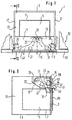
- a built-in cooking appliance 1 with a housing 3 has a cooking space 5 with a cooking chamber insulation 7 surrounding it. Not Heating elements shown in more detail are in the cooking chamber 5 for heating it intended. This is through on its front a cooking chamber door 9 lockable.
- Cooling chamber 11 formed. This is from a floor pan 13, a front panel 15 and side walls 17 of the housing 3 and a cover plate, not shown.
- the Cooling chamber 11 extends over the entire width of the device 1, the depth of the cooling chamber 11 being approximately one Third of the depth of the cooking device 1 is limited.
- the cooling chamber 11 is substantially opposite a surrounding housing space 19 completed.
- Their Blower intake opening 25 is approximately in the middle of the width of the Cooking device 1 arranged in the rear of the cooling chamber 11.
- the cooling air blower 23 continues to have on its blowing side an air guide plate 27, which together with the Floor plate 13 of the cooling chamber 11 in this area an exhaust air duct 29 form.
- the side walls 17th provided with suction openings 31. These are about yourself approximately triangularly extending suction area 33 (dotted limited area in Fig. 2) distributed in the front Area of the cooling chamber 11 to about half the height of the cooking appliance 1 extends downwards.
- To get out of the deeper too located suction openings 31 to be able to suck in air without the cooling chamber 11 over its entire width accordingly extend downward are at the outer edge areas the cooling chamber 11 in the region of the front housing edges Intake shafts 35 formed.
- the built-in cooking appliance 1 is in a kitchen furniture 51 built-in.
- This has a kitchen furniture door 53, which the Cooking chamber door 9 or the front area of the side walls 17 of the housing 3 are slightly spaced apart.
- the cooling air blower 23 is through the arrangement of the Intake openings 31 through the cooling air between the built-in furniture 51 and the built-in cooking device 1 ventilation openings 55 the cooling air from the front on the built-in furniture 51 or the furniture door 53 sucked in and through the fan suction openings 25 sucked into the cooling chamber 11 to the fan suction opening 25.
- both the built-in furniture 51 and the cooking appliance 1 in the range of its highest temperatures by the Cooling air is cooled, and the electrical components 21 are protected from excessive heating.
- the warmed up Cooling air is through the exhaust air duct 29 through the blow-out opening 37 of the cooking device 1 in the door handle 41 and finally blown out of the door handle blow-out opening 45 again to the front.
- the door handle 41 is cooled and on the other hand, a control panel 57 is arranged in the area Controls 59 in front of the ascending on the oven door.
- Hot air by means of the entire width of the cooking device 1 Protected air apron protected. Part of the blown out Cooling air is deflected in the door handle ventilation duct 43 and in the oven door 9 directed to its forced cooling.
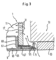
- FIG. 3 schematically shows the area between a side wall 17 and the built-in furniture 51 or the built-in furniture door 53 shown.
- a rectangular muffle flange 61 or its Muffle opening is through the cooking appliance door 9 with a door bottom 63 and a glass plate 65 closable.
- On the muffle flange 61 a seal 67 is attached, on which the Door 9 is supported in the closed position.
- the muffle flange 61 serves at the same time via a mounting bracket 69 for mounting the cooking space side walls 17.
- Towards the front is next to the muffle flange 61 one aligned with this Screen or pilaster 71 arranged when the Door 9 the gap between the housing side wall 17 and the built-in furniture 51 covered.
- Ventilation openings 55 are distributed in the front area of the pilaster strips and between an angled backwards, on the furniture supporting section of the pilasters 71 and the built-in furniture 51 or the kitchen furniture door 53 formed.
- Cooling air flowing through the pilaster also becomes 71 occurring heat transfer between the device 1 and the Built-in furniture 51 kept low.
Landscapes
- Engineering & Computer Science (AREA)
- Chemical & Material Sciences (AREA)
- Combustion & Propulsion (AREA)
- Mechanical Engineering (AREA)
- General Engineering & Computer Science (AREA)
- Electric Ovens (AREA)
- Cookers (AREA)
- Electric Stoves And Ranges (AREA)
Description
- Fig. 1
- eine Draufsicht auf das Gargerät bei abgenommener oberer Gehäusewandung,
- Fig. 2
- eine Schnittdarstellung im wesentlichen entlang der Linie II-II in Fig. 1 und
- Fig. 3
- eine schematische Teilschnittdraufsicht in vergrößertem Maßstab auf den Bereich zwischen dem Einbaugargerät und dem Einbaumöbel.
Claims (13)
- Einbaugargerät mit einem Gehäuse (3), das zwischen den Wänden eines Einbaumöbels eingebaut ist, derart, dass die Wände des Einbaumöbels den Seitenwänden des Gehäuses zumindest teilweise gering beabstandet gegenüberstehen, mit einem beheizbaren, thermisch isolierten Garraum (5), der an der Vorderseite durch eine Garraumtür (9) verschließbar ist, mit elektrischen Bauelementen (21) im Bereich hinter einer Bedienblende des Gargerätes, und mit Kühlluftführungsmittel sowie einem Kühlluftgebläse (23), das zur Kühlung Luft über Ansaug- und Ausblasöffnungen fördert, dadurch gekennzeichnet, dass als Kühlluftführungsmittel oberhalb des Garraums (5) eine gegenüber diesem und einem Umgebungs-Gehäuseraum (19) im wesentlichen geschlossene Kühlkammer (11) mit nachgeschaltetem Kühlluftgebläse (23) angeordnet ist, in der sich die Bauelemente (21) befinden, und wobei die Ansaugöffnungen (31) der Kühlkammer im vorderen Bereich der Seitenwände (17) des Gehäuses (3) angeordnet sind, und in welcher Kühlkammer das Kühlluftgebläse (23) einen Unterdruck zum Ansaugen der Kühlluft erzeugt, um die Kühlung im wesentlichen auf den vorderen Bereich zwischen den Seitenwänden (17) des Gehäuses (3) und den Wänden des Einbaumöbels (51) sowie auf die elektrischen Bauelemente zu (21) begrenzen.
- Einbaugargerät nach Anspruch 1, dadurch gekennzeichnet, dass die Kühlkammer (11) im Bereich der vertikalen, frontseitigen Gehäusekanten vertikale Ansaugschächte (35) besitzt.
- Einbaugargerät nach Anspruch 1 oder 2, dadurch gekennzeichnet, dass das Kühlluftgebläse (23) in der Kühlkammer (11) angeordnet ist.
- Einbaugerät nach Anspruch 1, 2 oder 3, dadurch gekennzeichnet, dass die Tiefe der Kühlkammer (11) etwa ein Drittel der Tiefe des Gargerätes (1) beträgt.
- Einbaugargerät nach einem der vorhergehenden Ansprüche, dadurch gekennzeichnet, dass ein Abluftkanal (29) des Kühlluftgebläses (23) am Boden der Kühlkammer (11) angeordnet ist.
- Einbaugargerät nach einem der vorhergehenden Ansprüche, dadurch gekennzeichnet, dass eine einen Spalt zwischen dem Einbaumöbel (51) und der Seitenwandung (17) des Einbaugargerätes (1) verdeckende Sichtblende (71) mit Lüftungsöffnungen (55) versehen ist.
- Einbaugargerät nach Anspruch 6, dadurch gekennzeichnet, dass die Lüftungsöffnungen (55) mindestens zum Teil zwischen der Sichtblende (71) und dem Einbaumöbel (51, 53) gebildet sind.
- Einbaugargerät nach einem der vorhergehenden Ansprüche, dadurch gekennzeichnet, dass die Ausblasöffnungen (37) an der Vorderseite des Gargerätes (1) angeordnet sind.
- Einbaugargerät nach Anspruch 8 mit an der Bedienblende gelagerten Bedienelementen, dadurch gekennzeichnet, dass die Ausblasöffnungen (37) unterhalb der Bedienelemente (59) angeordnet sind, und dass die ausgeblasene Kühlluft eine die Bedienelemente (59) vor der an der Garraumtür (9) aufsteigenden Heißluft schützende Luftschürze bildet.
- Einbaugargerät nach Anspruch 8 oder 9, dadurch gekennzeichnet, dass in einem Türgriff (41) der Garraumtür (9) ein Türgriff-Lüftungskanal (43) ausgebildet ist, und dass die Ausblasöffnungen (37) des Gargerätes (1) bei geschlossener Garraumtür (9) dem Türgriff-Lüftungskanal (43) zugeordnet sind zum Ausblasen der Kühlluft durch den Türgriff (41).
- Einbaugargerät nach Anspruch 8, 9 oder 10, dadurch gekennzeichnet, dass die Ausblasöffnungen (37) im wesentlichen über die gesamte Breite des Gargerätes (1) angeordnet sind.
- Einbaugargerät nach einem der Ansprüche 1 bis 5, dadurch gekennzeichnet, dass die Kammer (11) durch Abschnitte der Seitenwände (17) des Gehäuses (3), ein Frontblech (15) der Bedienblende (57), ein Bodenblech (13) und ein Deckelblech gebildet ist.
- Einbaugargerät nach Anspruch 12, dadurch gekennzeichnet, dass der Türgriff-Lüftungskanal (43) die ausgeblasene Kühlluft zumindest zum Teil ins Innere der Garraumtür (9) zu deren Kühlung führt.
Applications Claiming Priority (2)
| Application Number | Priority Date | Filing Date | Title |
|---|---|---|---|
| DE19504673A DE19504673C2 (de) | 1995-02-13 | 1995-02-13 | Einbaugargerät-Kühlung |
| DE19504673 | 1995-02-13 |
Publications (2)
| Publication Number | Publication Date |
|---|---|
| EP0726425A1 EP0726425A1 (de) | 1996-08-14 |
| EP0726425B1 true EP0726425B1 (de) | 2001-11-21 |
Family
ID=7753787
Family Applications (1)
| Application Number | Title | Priority Date | Filing Date |
|---|---|---|---|
| EP96101435A Expired - Lifetime EP0726425B1 (de) | 1995-02-13 | 1996-02-01 | Einbaugargerät-Kühlung |
Country Status (3)
| Country | Link |
|---|---|
| EP (1) | EP0726425B1 (de) |
| DE (2) | DE19504673C2 (de) |
| ES (1) | ES2168399T3 (de) |
Families Citing this family (9)
| Publication number | Priority date | Publication date | Assignee | Title |
|---|---|---|---|---|
| DE19903917B4 (de) * | 1999-02-01 | 2007-10-04 | BSH Bosch und Siemens Hausgeräte GmbH | Backofen mit frontseitigem Kühlluftspalt |
| DE19915538A1 (de) * | 1999-04-01 | 2000-10-05 | Bsh Bosch Siemens Hausgeraete | Einbaugargerät mit Luftfühlung |
| FR2858394B1 (fr) * | 2003-07-28 | 2005-10-14 | Brandt Ind | Four encastrable a parois laterales ventilees |
| DE102004015751A1 (de) * | 2004-03-31 | 2005-11-03 | Miele & Cie. Kg | Haushaltsgerät, insbesondere Gargerät |
| FR2876781B1 (fr) * | 2004-10-18 | 2007-01-26 | Brandt Ind Sas | Four de cuisson comportant un dispositif de ventilation des organes de commande |
| KR101650574B1 (ko) * | 2010-01-19 | 2016-08-23 | 엘지전자 주식회사 | 조리기기 |
| EP2901084B1 (de) * | 2012-09-28 | 2017-08-02 | Arçelik Anonim Sirketi | Ofen mit erhöhter lüftungseffizienz |
| DE102014202443A1 (de) * | 2014-02-11 | 2015-08-13 | BSH Hausgeräte GmbH | Kühlen von Türkomponenten |
| US10488054B2 (en) * | 2017-02-28 | 2019-11-26 | Haier Us Appliance Solutions, Inc. | Cooking appliance and cooling assembly therefor |
Citations (3)
| Publication number | Priority date | Publication date | Assignee | Title |
|---|---|---|---|---|
| DE2106869A1 (de) * | 1971-02-13 | 1972-09-07 | Neff Werke, Carl Neff GmbH, 7518Bretten | Haushaltsbackofen |
| DE2806158A1 (de) * | 1978-02-14 | 1979-09-06 | Bosch Siemens Hausgeraete | Doppelbackofen, insbesondere einbaubackofen |
| DE3104677A1 (de) * | 1981-02-10 | 1982-08-12 | Bosch Siemens Hausgeraete | Backofen, vorzugsweise mit einer thermischen heizeinrichtung sowie mit einer mikrowellen-heizeinrichtung |
Family Cites Families (10)
| Publication number | Priority date | Publication date | Assignee | Title |
|---|---|---|---|---|
| DE1691818U (de) * | 1954-11-05 | 1955-01-20 | Frank Sche Eisenwerke Ag | Schalterblende. |
| DE2349388B2 (de) * | 1973-10-02 | 1977-06-30 | Bauknecht Gmbh G | Einbauherd |
| DE7604165U1 (de) * | 1976-02-13 | 1976-09-02 | Stephan Witte & Comp, 5860 Iserlohn | Belueftetes einbaugeraet |
| IT1083338B (it) * | 1977-01-26 | 1985-05-21 | Smeg Elettrodomestici | Forno perfezionato con raffreddamento esterno ad aria forzata |
| DE2825461A1 (de) | 1978-06-09 | 1979-12-13 | Bosch Siemens Hausgeraete | Doppelbackofen, insbesondere einbaubackofen |
| DE8019911U1 (de) * | 1980-07-24 | 1980-10-23 | Bosch-Siemens Hausgeraete Gmbh, 7000 Stuttgart | Backofen |
| DE8034134U1 (de) * | 1980-12-22 | 1981-05-27 | Bosch-Siemens Hausgeräte GmbH, 7000 Stuttgart | Backofen |
| DE8130645U1 (de) * | 1981-10-20 | 1986-01-23 | Bosch-Siemens Hausgeräte GmbH, 7000 Stuttgart | Einrichtung zur Kühlung elektrischer oder elektronischer Schaltungsanordnungen im Schalterraum oberhalb eines Backofens |
| DE8806275U1 (de) | 1988-05-11 | 1988-06-23 | Bosch-Siemens Hausgeräte GmbH, 8000 München | Backofen |
| DE3839657C2 (de) * | 1988-11-24 | 1993-11-18 | Miele & Cie | Luftführungssystem für einen Backofen |
-
1995
- 1995-02-13 DE DE19504673A patent/DE19504673C2/de not_active Revoked
-
1996
- 1996-02-01 EP EP96101435A patent/EP0726425B1/de not_active Expired - Lifetime
- 1996-02-01 ES ES96101435T patent/ES2168399T3/es not_active Expired - Lifetime
- 1996-02-01 DE DE59608222T patent/DE59608222D1/de not_active Expired - Lifetime
Patent Citations (3)
| Publication number | Priority date | Publication date | Assignee | Title |
|---|---|---|---|---|
| DE2106869A1 (de) * | 1971-02-13 | 1972-09-07 | Neff Werke, Carl Neff GmbH, 7518Bretten | Haushaltsbackofen |
| DE2806158A1 (de) * | 1978-02-14 | 1979-09-06 | Bosch Siemens Hausgeraete | Doppelbackofen, insbesondere einbaubackofen |
| DE3104677A1 (de) * | 1981-02-10 | 1982-08-12 | Bosch Siemens Hausgeraete | Backofen, vorzugsweise mit einer thermischen heizeinrichtung sowie mit einer mikrowellen-heizeinrichtung |
Also Published As
| Publication number | Publication date |
|---|---|
| DE19504673A1 (de) | 1996-08-14 |
| EP0726425A1 (de) | 1996-08-14 |
| DE59608222D1 (de) | 2002-01-03 |
| DE19504673C2 (de) | 1998-04-30 |
| ES2168399T3 (es) | 2002-06-16 |
Similar Documents
| Publication | Publication Date | Title |
|---|---|---|
| DE69634223T2 (de) | Luftstromvorrichtung für Mikrowellenofen | |
| DE2825461C2 (de) | ||
| EP0752561B1 (de) | Backofen | |
| US4616562A (en) | Ventilation system for pizza ovens | |
| DE19505469C1 (de) | Anordnung für die Zuführung von Primärluft zu einem atmosphärischen Gasbrenner über einer Kochplatte aus Glaskeramik | |
| EP0512716B1 (de) | Kochgerät | |
| GB2026685A (en) | Cooling Built-in Double Ovens | |
| EP1004826B1 (de) | Garofen mit Kühlung und Wrasenabführung | |
| DE19920345C1 (de) | Garofen mit Wrasenabführung und Frischluftbeimischung | |
| DE19504673C2 (de) | Einbaugargerät-Kühlung | |
| EP0947776B1 (de) | Garofen mit Kühleinrichtung | |
| DE3024445C2 (de) | Gasherd mit Strahlungsbrenner | |
| EP0633433B1 (de) | Einbauherd | |
| DE2106869A1 (de) | Haushaltsbackofen | |
| DE2615604B2 (de) | Backofen, insbesondere mit Mitteln zur pyrolytischen Reinigung mit einem Kühlluftgebläse | |
| EP0003764B1 (de) | Doppelbackofen, insbesondere Einbaubackofen | |
| DE19817197A1 (de) | Anordnung mit Backofen und Kochfeld | |
| EP0913646B1 (de) | Herd mit gekühlter Beleuchtungseinrichtung | |
| DE4033989C2 (de) | ||
| DE19861077C2 (de) | Gargerät mit Backofendichtung | |
| EP2444738B1 (de) | Gargerät mit einem Backofen | |
| DE29522236U1 (de) | Einbaugargerät-Kühlung | |
| DE2167022C3 (de) | Haushaltsbackofen | |
| DE4339877A1 (de) | Einbau-Glaskeramikkochplatte mit mehreren induktionsbeheizten Kochstellen | |
| DE102007007542A1 (de) | Backofen mit einer Mikrowelleneinrichtung |
Legal Events
| Date | Code | Title | Description |
|---|---|---|---|
| PUAI | Public reference made under article 153(3) epc to a published international application that has entered the european phase |
Free format text: ORIGINAL CODE: 0009012 |
|
| AK | Designated contracting states |
Kind code of ref document: A1 Designated state(s): DE ES FR GB IT SE |
|
| 17P | Request for examination filed |
Effective date: 19970124 |
|
| RAP1 | Party data changed (applicant data changed or rights of an application transferred) |
Owner name: BSH BOSCH UND SIEMENS HAUSGERAETE GMBH |
|
| 17Q | First examination report despatched |
Effective date: 19980821 |
|
| TPAD | Observations filed by third parties |
Free format text: ORIGINAL CODE: EPIDOS TIPA |
|
| GRAG | Despatch of communication of intention to grant |
Free format text: ORIGINAL CODE: EPIDOS AGRA |
|
| GRAG | Despatch of communication of intention to grant |
Free format text: ORIGINAL CODE: EPIDOS AGRA |
|
| GRAH | Despatch of communication of intention to grant a patent |
Free format text: ORIGINAL CODE: EPIDOS IGRA |
|
| GRAH | Despatch of communication of intention to grant a patent |
Free format text: ORIGINAL CODE: EPIDOS IGRA |
|
| GRAA | (expected) grant |
Free format text: ORIGINAL CODE: 0009210 |
|
| AK | Designated contracting states |
Kind code of ref document: B1 Designated state(s): DE ES FR GB IT SE |
|
| GBT | Gb: translation of ep patent filed (gb section 77(6)(a)/1977) |
Effective date: 20011121 |
|
| REG | Reference to a national code |
Ref country code: GB Ref legal event code: IF02 |
|
| REF | Corresponds to: |
Ref document number: 59608222 Country of ref document: DE Date of ref document: 20020103 |
|
| ET | Fr: translation filed | ||
| REG | Reference to a national code |
Ref country code: ES Ref legal event code: FG2A Ref document number: 2168399 Country of ref document: ES Kind code of ref document: T3 |
|
| PLBE | No opposition filed within time limit |
Free format text: ORIGINAL CODE: 0009261 |
|
| STAA | Information on the status of an ep patent application or granted ep patent |
Free format text: STATUS: NO OPPOSITION FILED WITHIN TIME LIMIT |
|
| 26N | No opposition filed | ||
| PGFP | Annual fee paid to national office [announced via postgrant information from national office to epo] |
Ref country code: ES Payment date: 20040209 Year of fee payment: 9 |
|
| PGFP | Annual fee paid to national office [announced via postgrant information from national office to epo] |
Ref country code: SE Payment date: 20040227 Year of fee payment: 9 |
|
| PG25 | Lapsed in a contracting state [announced via postgrant information from national office to epo] |
Ref country code: SE Free format text: LAPSE BECAUSE OF NON-PAYMENT OF DUE FEES Effective date: 20050202 Ref country code: ES Free format text: LAPSE BECAUSE OF NON-PAYMENT OF DUE FEES Effective date: 20050202 |
|
| EUG | Se: european patent has lapsed | ||
| REG | Reference to a national code |
Ref country code: ES Ref legal event code: FD2A Effective date: 20050202 |
|
| PGFP | Annual fee paid to national office [announced via postgrant information from national office to epo] |
Ref country code: GB Payment date: 20070221 Year of fee payment: 12 |
|
| PGFP | Annual fee paid to national office [announced via postgrant information from national office to epo] |
Ref country code: IT Payment date: 20070531 Year of fee payment: 12 |
|
| PGFP | Annual fee paid to national office [announced via postgrant information from national office to epo] |
Ref country code: FR Payment date: 20070216 Year of fee payment: 12 |
|
| GBPC | Gb: european patent ceased through non-payment of renewal fee |
Effective date: 20080201 |
|
| REG | Reference to a national code |
Ref country code: FR Ref legal event code: ST Effective date: 20081031 |
|
| PG25 | Lapsed in a contracting state [announced via postgrant information from national office to epo] |
Ref country code: FR Free format text: LAPSE BECAUSE OF NON-PAYMENT OF DUE FEES Effective date: 20080229 |
|
| PG25 | Lapsed in a contracting state [announced via postgrant information from national office to epo] |
Ref country code: GB Free format text: LAPSE BECAUSE OF NON-PAYMENT OF DUE FEES Effective date: 20080201 |
|
| PG25 | Lapsed in a contracting state [announced via postgrant information from national office to epo] |
Ref country code: IT Free format text: LAPSE BECAUSE OF NON-PAYMENT OF DUE FEES Effective date: 20080201 |
|
| PGFP | Annual fee paid to national office [announced via postgrant information from national office to epo] |
Ref country code: DE Payment date: 20130228 Year of fee payment: 18 |
|
| REG | Reference to a national code |
Ref country code: DE Ref legal event code: R119 Ref document number: 59608222 Country of ref document: DE |
|
| REG | Reference to a national code |
Ref country code: DE Ref legal event code: R119 Ref document number: 59608222 Country of ref document: DE Effective date: 20140902 |
|
| PG25 | Lapsed in a contracting state [announced via postgrant information from national office to epo] |
Ref country code: DE Free format text: LAPSE BECAUSE OF NON-PAYMENT OF DUE FEES Effective date: 20140902 |