EP0725025B1 - Sheet guiding device for printing machines - Google Patents
Sheet guiding device for printing machines Download PDFInfo
- Publication number
- EP0725025B1 EP0725025B1 EP95119931A EP95119931A EP0725025B1 EP 0725025 B1 EP0725025 B1 EP 0725025B1 EP 95119931 A EP95119931 A EP 95119931A EP 95119931 A EP95119931 A EP 95119931A EP 0725025 B1 EP0725025 B1 EP 0725025B1
- Authority
- EP
- European Patent Office
- Prior art keywords
- nozzles
- air
- sheet
- guide surface
- guide
- Prior art date
- Legal status (The legal status is an assumption and is not a legal conclusion. Google has not performed a legal analysis and makes no representation as to the accuracy of the status listed.)
- Expired - Lifetime
Links
Images


Classifications
-
- B—PERFORMING OPERATIONS; TRANSPORTING
- B41—PRINTING; LINING MACHINES; TYPEWRITERS; STAMPS
- B41F—PRINTING MACHINES OR PRESSES
- B41F25/00—Devices for pressing sheets or webs against cylinders, e.g. for smoothing purposes
-
- B—PERFORMING OPERATIONS; TRANSPORTING
- B65—CONVEYING; PACKING; STORING; HANDLING THIN OR FILAMENTARY MATERIAL
- B65H—HANDLING THIN OR FILAMENTARY MATERIAL, e.g. SHEETS, WEBS, CABLES
- B65H29/00—Delivering or advancing articles from machines; Advancing articles to or into piles
- B65H29/02—Delivering or advancing articles from machines; Advancing articles to or into piles by mechanical grippers engaging the leading edge only of the articles
- B65H29/04—Delivering or advancing articles from machines; Advancing articles to or into piles by mechanical grippers engaging the leading edge only of the articles the grippers being carried by endless chains or bands
- B65H29/041—Delivering or advancing articles from machines; Advancing articles to or into piles by mechanical grippers engaging the leading edge only of the articles the grippers being carried by endless chains or bands and introducing into a pile
-
- B—PERFORMING OPERATIONS; TRANSPORTING
- B65—CONVEYING; PACKING; STORING; HANDLING THIN OR FILAMENTARY MATERIAL
- B65H—HANDLING THIN OR FILAMENTARY MATERIAL, e.g. SHEETS, WEBS, CABLES
- B65H29/00—Delivering or advancing articles from machines; Advancing articles to or into piles
- B65H29/02—Delivering or advancing articles from machines; Advancing articles to or into piles by mechanical grippers engaging the leading edge only of the articles
- B65H29/06—Delivering or advancing articles from machines; Advancing articles to or into piles by mechanical grippers engaging the leading edge only of the articles the grippers being carried by rotating members
-
- B—PERFORMING OPERATIONS; TRANSPORTING
- B65—CONVEYING; PACKING; STORING; HANDLING THIN OR FILAMENTARY MATERIAL
- B65H—HANDLING THIN OR FILAMENTARY MATERIAL, e.g. SHEETS, WEBS, CABLES
- B65H5/00—Feeding articles separated from piles; Feeding articles to machines
- B65H5/08—Feeding articles separated from piles; Feeding articles to machines by grippers, e.g. suction grippers
- B65H5/12—Revolving grippers, e.g. mounted on arms, frames or cylinders
-
- B—PERFORMING OPERATIONS; TRANSPORTING
- B65—CONVEYING; PACKING; STORING; HANDLING THIN OR FILAMENTARY MATERIAL
- B65H—HANDLING THIN OR FILAMENTARY MATERIAL, e.g. SHEETS, WEBS, CABLES
- B65H5/00—Feeding articles separated from piles; Feeding articles to machines
- B65H5/36—Article guides or smoothers, e.g. movable in operation
- B65H5/38—Article guides or smoothers, e.g. movable in operation immovable in operation
-
- B—PERFORMING OPERATIONS; TRANSPORTING
- B65—CONVEYING; PACKING; STORING; HANDLING THIN OR FILAMENTARY MATERIAL
- B65H—HANDLING THIN OR FILAMENTARY MATERIAL, e.g. SHEETS, WEBS, CABLES
- B65H2406/00—Means using fluid
- B65H2406/10—Means using fluid made only for exhausting gaseous medium
- B65H2406/11—Means using fluid made only for exhausting gaseous medium producing fluidised bed
-
- B—PERFORMING OPERATIONS; TRANSPORTING
- B65—CONVEYING; PACKING; STORING; HANDLING THIN OR FILAMENTARY MATERIAL
- B65H—HANDLING THIN OR FILAMENTARY MATERIAL, e.g. SHEETS, WEBS, CABLES
- B65H2406/00—Means using fluid
- B65H2406/30—Suction means
Definitions
- the invention relates to a sheet guiding device for Printing machines with guide surfaces for guiding the sheet, being in the guide surfaces nozzles are provided, which with blown air or Suction air can be acted upon.
- the advantage of the invention is that in the preferred operating mode, the blown air mode, the Printing machine capable of through the tangential air flow all printing materials to be processed are safe and to be lubricated-free. This is done through the leadership of the Arch on an air flow caused by the tangential and rectified blowing direction of the nozzles from several individual streams to one main stream with one united flow direction united.
- This pouring Air cushion is due to its uniformity and Uniformity able to bow without touching the sheet guide plates and thus free of grease, even in the case that both sides of the sheets are freshly printed. This is especially true at all machine speeds possible with shorter set-up times as a time-consuming adjustment of the air flow to the substrate and the speed of the press is very rare becomes necessary.
- the invention provides that in straight printing a Conversion of the sheet guide is possible through the problematic areas of the sheet run a suction takes place, the sheet metal touching the unprinted sides of the Bow can result.
- Such sheet metal contact In this case it does no harm, but can lead to one lead to a significant reduction in machine set-up time.
- sheets become clean and smooth on the sheet led along. You will experience a braking force, the one Tightening causes so that the bow without this any formation of wrinkles and air pockets the next Printing cylinders can be passed.
- the outlet areas of the guide surfaces are expedient of the sheet-guiding drums located upstream of the printing cylinders designed to be acted upon by suction air. With these drums can be transfer drums between the Printing cylinders of the individual printing units are arranged. It However, it is also possible that between the printing cylinders several sheet transport drums are arranged. In the Sheet transport drum in front of the first impression cylinder a feed drum that feeds the sheet from the feeder takes over and transported to the printing cylinder. It However, it is also possible that another in this area Transport drum is provided. A clean sheet guide is with the sheet leading upstream of the impression cylinders Drums are particularly important because of the support of the bow on the printing cylinders and thus the quality of the print depends.
- Air supply is via axial fans, which are related their direction of rotation are switchable. This allows you to very simple way to switch the desired one Carry out sections of the printing press.
- Air supply box It is possible to pass through relatively large nozzles individually To supply fans with the desired air, or an air supply can be provided at which individual areas or parts of the air supply via Air supply box is done. There is at least one Subdivision of the guiding surfaces into areas required either blowing or suction air can be applied and those areas of the guide surfaces, which are preferably only in Blown air operation can be operated. It goes without saying further subdivision possible, according to how strong the Air exposure in a specific area Guide surface has to take place.
- the advantage of air supply boxes is that many nozzles by means of a Air supply element can be supplied. So for a larger number of nozzles, for example strong axial fans are used. Through the It is still possible to subdivide the individual areas to apply air to the guide surfaces variably. Therefore it is proposed that each blow box have an axial fan assign and the size of the air supply boxes to the Adjust air requirements in the respective areas.
- control surfaces a different, adapted to the respective air requirement Have area coverage with nozzles.
- the inlet and outlet areas of the guide surfaces a higher area occupancy and those in between Leadership zones with a lower area allocation too Mistake.
- the switch to suction operation by a Remote control is time saving when the machine is off Backprint on straight printing or on the operation with problematic papers to be converted. Very easy can do this by electronic control of the Axial fans or other fans take place.
- Fig. 1 shows a schematic representation of a Printing machine with an embodiment of an inventive Sheet guiding device.
- the printing press are for simple representation of only two printing units 20 and 20 ' shown; usually has such a printing press however over four and more printing units.
- Each printing unit 20, 20 ' has a pressure cylinder 8, 8 ', Rubber cylinder 9, 9 'and a plate cylinder 10, 10' and about ink works not shown.
- Between the printing units 20 and 20 ' provides a transfer drum 6 for forwarding the sheet to be printed 4.
- Has a printing press multiple printing units, so there are always between two printing units Transfer drums 6 arranged. Of course it is possible that 6 instead of a transfer drum Sheet transport drums are arranged.
- the sheet track 17 is shown, wherein arrows 24 show the direction of sheet travel.
- the arch 4 are removed from a feeder stack 19 and by means of a feeder, not shown, to a feed drum 5 passed on the sheet 4 with their grippers one Printing cylinder 8 passes for printing. From the impression cylinder 8 the sheet 4 is gripped by the gripper 26 of the transfer drum 6 taken over and fed to a further pressure cylinder 8 ', so that further printing can take place.
- Die Delivery drum 7 is the transfer drum for gripper bridges, which are arranged on the boom chain 22 and which the sheet 4 taken over to the end of the jib 21 transport where the sheets 4 on the delivery stack 23rd be filed.
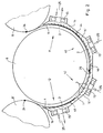
- Sections 3 include this Baffles 1 arranged, preferably a number of have slot-shaped nozzles 2. These are in the 1 not shown, but they are to take the example of the transfer drum 6 of FIG. 2.
- the Nozzles 2 are constructed in such a way that at least some of the nozzles 2 their blowing air essentially tangent to the surface of the Guide surface 1 in the between the arch 4 and the guide surface 1st supplies formed area.
- the angle between airflow and Surface can be between 0.1 ° and 30 °, for example be.
- the arrangement of the nozzles 2 and the blowing direction the same is further preferably chosen so that the Air flows from adjacent nozzle groups to one Total flow with essentially parallel streamlines overlay.
- the guide surface 1 on the transfer drum 6 shows a total of four separated by partitions 44, 46, 48 Nozzle areas 11, 12, 40, 42, which by a Axial fan 15 are charged with air.
- the Nozzle areas 11, 12, 40, 42 consist of several nozzles 2, seen in the direction of Fig. 2 one behind the other are arranged.
- the arrows 25 show the possible Blowing direction of the axial fans 15.
- a sheet 4, which from the pressure cylinder 8 by means of a gripper row 26 was taken over by the transfer drum 6, the Printing cylinder 8 'transported further.
- the bow 4 experiences a levitation in which it between the transfer drum 6 and the guide surface 1 without touching the guide surface 1 is guided.
- a levitation is for example in reverse printing, since none of the Sides of the sheet 4 on the transfer drum 6 or on the Lubricate guide surfaces 1.
- the bow 4 is thereby held in the inlet area 11, so that it at slow machine operation or when the machine stops with its rear end not falling down and it as a result, the sheet 4 cannot be folded.
- the suction operation in the outlet area 12 leads to a tightening of sheet 4, making labile papers, especially those with low basis weight, e.g. Bible papers, also at transfer maximum speed to the pressure cylinder 8 and therefore neither waves nor air pockets exhibit. This way, even problematic papers with high quality and greatest speed under Compliance with minimum machine set-up times can be printed.
- a guide of the arch 4 along the guide surfaces 1 in Outlet area 12 can also be used for less problematic Papers can be helpful when using the printing press For example, it runs accordingly fast and therefore high Centrifugal forces act on the bow 4, this this to the outside drive, which can cause the sheet 4 to flutter. Also in this case, the guide described by Holding forces generated in both blowing and suction operation on the sheet 4 along the guide surfaces 1 serve that the sheet 4 is neatly applied to the impression cylinder 8 '.
- Axial fans 15 can be arranged for sheet guidance, which are used to safely secure the sheet 4 to the delivery stack 23 transport or to the fact that they are above the delivery stack 23 are acted upon with blowing air in such a way that they become place it quickly on delivery pile 23.
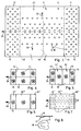
- FIG. 3 shows a guide surface 1 which has nozzles 2 which by means of air supply boxes 16 and 16 'with air be charged.
- the areal density of the as Slit nozzles 18 formed nozzles 2 is preferred trained differently. So are in the inlet area 11th two air supply boxes 16 arranged, which are high Have surface density at nozzles 2. Then comes one Guide zone 14 with a surface density of nozzles 2, which in middle area is stronger and weaker at the edges.
- This guide zone 14 corresponds e.g. the Nozzle areas 40, 42, in which a blowing air is applied is sufficient for every operation of the printing press.
- the outlet area 12 which has a higher nozzle density has, and in the relatively large suction air operation Holding forces must act on the arch 4.
- Fig. 6 shows how with less air requirement on a Subdivision can be dispensed with, so that in the inlet area 11 and in the discharge area 12 each a blow box 16 and in a large blow box 16 '' 'is arranged in the guide zone 14 is.
- the nozzle arrangement which is is shown in Fig. 7.
- FIG. 8 shows the preferred embodiment of the nozzles 2, which has already been indicated in Fig. 3. It is a matter of Slot nozzles 18, which in the sheet metal of the guide surfaces 1 are easy to punch. The one shown in Fig. 3 The blowing direction is directed outwards (Arrows 50), causing a tightening of the arch 4 across its direction of travel is achieved. For this purpose it is required that two strong outwards in the middle directed air currents are formed, which are to the side of the Move bow 4, and the outside with a smaller Number of nozzles 2, 18 can be maintained.
- FIG Invention In a preferred embodiment of FIG Invention are in the inlet area 11 and / or Outflow area 12 of the guide surface 1, nozzle areas 52, 54 provided, the nozzles depending on the to be processed Printing material can be switched between blowing and suction operation.
- the remaining nozzles of the guide surface 1 are in this Embodiment of the invention preferably in the blowing mode operated.
- the nozzle areas 52, 54 preferably have each have a fan 15 assigned to them preferably arranged centrally to the sheet raceway 17 and have a width less than the smallest of sheet format that can be processed by the printing press.
- the exemplary embodiments merely represent possibilities of Design of the sheet guide device according to the invention, further embodiments with different nozzle arrangements, possibly other blowing directions are also possible.
- the Axial fans 15 can also provide a central air supply with blowing and suction air or another type of fan be used.
Description
Die Erfindung betrifft eine Bogenleiteinrichtung für Druckmaschinen mit Leitflächen zum Führen der Bogen, wobei in den Leitflächen Düsen vorgesehen sind, die mit Blasluft oder Saugluft beaufschlagbar sind.The invention relates to a sheet guiding device for Printing machines with guide surfaces for guiding the sheet, being in the guide surfaces nozzles are provided, which with blown air or Suction air can be acted upon.
Eine derartige Bogenleiteinrichtung ist aus der DE 34 11 029 C2 bekannt. Bei dieser Bogenleiteinrichtung wird versucht, eine sichere Schwebeführung der Bogen dadurch zu erzielen, daß Düsen in Form von senkrecht in den Leitflächen angeordneten Bohrungen einen bestimmten Flächenanteil der Leitfläche ausmachen. Nachteilig bei dieser Bogenleiteinrichtung ist es, daß die Düsen senkrecht gegen den zu führenden Bogen gerichtet sind. Die aus den Düsen austretende Luft prallt gegen den Bogen, muß von diesem unter Aufbringung von Kräften umgelenkt werden und strömt dann von der Düseneinblasstelle aus radial unter 360° nach allen Seiten ab. Die aus der Umlenkung resultierenden Impulskräfte regen den Bogen zum Flattern an. Um durch diese instabilen und turbulenten Düsenfreistrahlen einen Bogen stabil zu führen, ist es notwendig die Impulskraft sehr feinfühlig auf den jeweiligen Bedruckstoff einzustellen. Der Vordruck der eingeblasenen Luft darf dabei nur minimal sein. Um jedoch dennoch den gesamten Bogenleitbereich abschmierfrei zu halten, ist ein hoher Volumenstrom und um diesen zu erzeugen, ein ganz bestimmter Flächenanteil von Düsenbohrungen in der Führungsebene notwendig.Such a sheet guide device is from the DE 34 11 029 C2 known. With this sheet guiding device tries to hover the bow safely achieve nozzles in the form of perpendicular in the guide surfaces arranged holes a certain proportion of the area Identify the guiding surface. A disadvantage of this Sheet guiding device is that the nozzles are perpendicular against the bow to be guided. The one from the nozzles escaping air bounces against the bow, must be under it Application forces are redirected and then flows from the nozzle injection point from radially under 360 ° after all Pages from. The impulse forces resulting from the deflection stimulate the bow to flutter. To be unstable through this and turbulent jet clear jets stably lead, it is necessary to apply the impulse force very sensitively adjust the respective substrate. The form of the air blown in must be minimal. However, to nonetheless, the entire sheet guiding area must be greased hold is a high volume flow and to generate this a very specific proportion of the area of nozzle bores in the Management level necessary.
Weiterhin sind bei der Vorrichtung nach der DE 34 11 029 die den Düsen entströmenden Luftvolumen, nach deren Umlenkung durch den Bogen, den gleichen Luftvolumina der benachbarten Düsen entgegengerichtet. Diese einander entgegengerichteten Volumina prallen aufeinander und erzeugen um die Düsen herum Bereiche mit Turbulenzfeldern in denen die Düsenluft verwirbelt und die kinetische Energie der Düsenluft aufgezehrt wird.Furthermore, in the device according to DE 34 11 029 Air volume flowing out of the nozzles, after their deflection through the arch, the same air volumes of the neighboring Nozzles directed opposite. These face each other Volumes collide and create around the nozzles Areas with turbulence fields where the jet air swirls and the kinetic energy of the jet air is consumed.
In diesen Zonen erfolgt infolge der starken Wirbelbildung eine Störung des Bogentransports. Die Bogen werden zum Flattern und zu Schwingungen angeregt und besonders die Hinterkante führt peitschende Bewegungen aus. Die Möglichkeit, einen beidseitig bedruckten Bogen abschmierfrei zu führen ist damit, wenn überhaupt, nur bei niedriger Maschinengeschwindigkeit und unter erheblichem zeitaufwand für die Einstellung der an sich instabilen Blasluftfreistrahlen gegeben. Um eine Maschine dennoch betreiben zu können, werden die Düsen mit Saugluft beaufschlagt und erzeugen erst unter Reibung eine Bogenführung, die höhere Geschwindigkeiten der Druckmaschine zuläßt. Soll nun ein beidseitig bedruckter Bogen verarbeitet werden, so sind auf der Rückseite Bereiche notwendig, welche unbedruckt bleiben müssen. In diesen Bereichen können die saugenden Bohrungen aktiv werden. Dazwischen ist es dann möglich durch Blasluft die bedruckten Bogen am Abschmieren zu hindern, da die Bogenhaltekräfte je nur von den saugenden Bereichen erzeugt werden.In these zones, due to the strong vortex formation a disruption of sheet transport. The bows become Flutter and excited to vibrate and especially the Trailing edge carries out lashing movements. The Possibility of smear-free a sheet printed on both sides it can only be managed, if at all, at a lower rate Machine speed and takes a considerable amount of time for the adjustment of the inherently unstable Blown air free jets given. A machine anyway to be able to operate, the nozzles with suction air acted upon and only generate one under friction Sheet guide, the higher speeds of the printing press allows. Now a sheet printed on both sides should be processed areas are necessary on the back, which must remain blank. In these areas, the absorbing holes become active. It is in between possible by blowing air on the printed sheets to lubricate prevent, since the sheet holding forces only ever from the sucking Areas are created.
Der Erfindung liegt die Aufgabe zugrunde, eine Bogenleiteinrichtung zu schaffen, die die Nachteile des Standes der Technik vermeidet und die einen sicheren Bogenlauf bei unterschiedlichen Bedruckstoffen im Schöndruck wie auch in Schön- und Widerdruck unter minimalen Rüstzeiten sicherstellt.The invention has for its object a To create sheet guide, which has the disadvantages of Avoids state of the art and a safe Sheet run with different substrates in straight printing as well as in perfecting with minimal set-up times ensures.
Diese Aufgabe wird gemäß der Erfindung durch die Merkmale der
Ansprüche 1 und 2 gelöst. Weitere Merkmale der Erfindung sind
in den Unteransprüchen enthalten.This object is achieved according to the invention by the features of
Der Vorteil der Erfindung besteht darin, daß in der bevorzugten Betriebsart, dem Blasluftbetrieb, die Druckmaschine durch die tangentiale Luftströmung in der Lage ist alle zu verarbeitenden Bedruckstoffe sicher und abschmierfrei zu führen. Dies geschieht durch die Führung der Bogen auf einem Luftstrom, welcher bedingt durch die tangentiale und gleichgerichtete Blasrichtung der Düsen, sich aus mehreren Einzelströmen zu einer Hauptströmung mit einer einheitlichen Strömungsrichtung vereint. Dieses strömende Luftpolster ist durch seine Gleichmäßigkeit und Einheitlichkeit dazu in der Lage, den Bogen ohne Berührungen der Bogenleitbleche und damit abschmierfrei, auch im Falle, daß beide Seiten der Bogen frisch bedruckt sind, zu führen. Insbesondere ist dies bei allen Maschinengeschwindigkeiten unter kürzeren Rüstzeitaufwänden möglich, da ein zeitaufwendiges Anpassen der Luftströmung an den Bedruckstoff und die Geschwindigkeit der Druckmaschine nur sehr selten notwendig wird. Um eine Maschine, welche wahlweise im Schöndruck oder im Schön- und Widerdruck betrieben wird, im Falle des Verarbeitens von berührungsunempfindlichen Bogenrückseiten auch bei höchsten Maschinengeschwindigkeiten schnellstmöglich, d. h. mit minimalen Rüst- und Einstellzeiten, in den Zustand eines sicheren Fortdrucks zu versetzen, sieht die Erfindung vor, daß im Schöndruck eine Umstellung der Bogenführung möglich ist, durch die an problematischen Stellen des Bogenlaufs ein saugbetrieb erfolgt, der eine Blechberührung der unbedruckten Seiten der Bogen zur Folge haben kann. Eine solche Blechberührung schadet in diesem Falle nicht, kann jedoch zu einer bedeutenden Verkürzung der Maschinenrüstzeit führen. Die Bogen werden in diesem Falle sauber und glatt am Blech entlanggeführt. Sie erfahren dabei eine Bremskraft, die eine Straffung bewirkt, so daß auch auf diese Weise die Bogen ohne jegliche Bildung von Falten und Luftpolstern dem nächsten Druckzylinder übergeben werden können.The advantage of the invention is that in the preferred operating mode, the blown air mode, the Printing machine capable of through the tangential air flow all printing materials to be processed are safe and to be lubricated-free. This is done through the leadership of the Arch on an air flow caused by the tangential and rectified blowing direction of the nozzles from several individual streams to one main stream with one united flow direction united. This pouring Air cushion is due to its uniformity and Uniformity able to bow without touching the sheet guide plates and thus free of grease, even in the case that both sides of the sheets are freshly printed. This is especially true at all machine speeds possible with shorter set-up times as a time-consuming adjustment of the air flow to the substrate and the speed of the press is very rare becomes necessary. To a machine, which is optionally in the Straight printing or in perfecting is operated in Case of processing of touch-insensitive Back of sheets even at the highest machine speeds as soon as possible, d. H. with minimal setup and Response times, in the state of a safe continued printing move, the invention provides that in straight printing a Conversion of the sheet guide is possible through the problematic areas of the sheet run a suction takes place, the sheet metal touching the unprinted sides of the Bow can result. Such sheet metal contact In this case it does no harm, but can lead to one lead to a significant reduction in machine set-up time. The In this case, sheets become clean and smooth on the sheet led along. You will experience a braking force, the one Tightening causes so that the bow without this any formation of wrinkles and air pockets the next Printing cylinders can be passed.
Die mit Saugluft beaufschlagbaren Bereiche oder Sektionen der Druckmaschine sind vorzugsweise an allen bogenführenden Trommeln angeordnet, da es in deren Fliehkraftbereich leicht zu Bogenlaufstörungen kommt. Bei diesen Trommeln handelt es sich zum Beispiel um die sich an den Anleger anschließende Zuführtrommel, um die zwischen den Druckwerken angeordneten Umführtrommeln sowie um die Auslagetrommel, mit der der Ausleger die Bogen vom letzten Druckwerk übernimmt. Falls zusätzliche Umführtrommeln in die Maschine eingebaut sind, sollten auch dort Leitflächen angebracht werden, die in problematischen Bereichen mit Saugluft beaufschlagbar sind. Ebenso ist die Anordnung von mit Saugluft beaufschlagbaren Bereichen auch im Ausleger, zum Beispiel vor der Bogenbremse möglich.The areas or sections of the Printing presses are preferably on all sheet-guiding Drums arranged as it is easy in their centrifugal range comes to sheet running disturbances. These drums are for example, the one following the investor Feed drum to the arranged between the printing units Transfer drums and around the delivery drum with which the The delivery takes over the sheets from the last printing unit. If additional Transfer drums are built into the machine, guide surfaces should also be attached there, which are in problematic areas can be supplied with suction air. The arrangement of suction air can also be arranged Areas also in the boom, for example in front of the sheet brake possible.
Zweckmäßigerweise werden die Auslaufbereiche der Leitflächen der den Druckzylindern vorgeordneten bogenführenden Trommeln mit Saugluft beaufschlagbar ausgebildet. Bei diesen Trommeln kann es sich um Umführtrommeln handeln, die zwischen den Druckzylindern der einzelnen Druckwerke angeordnet sind. Es ist jedoch auch möglich, daß zwischen den Druckzylindern mehrere Bogentransporttrommeln angeordnet sind. Bei der Bogentransporttrommel vor dem ersten Druckzylinder handelt es sich um eine Zuführtrommel, die den Bogen vom Anleger übernimmt und an den Druckzylinder weitertransportiert. Es ist jedoch auch möglich, daß in diesem Bereich eine weitere Transporttrommel vorgesehen ist. Eine saubere Bogenführung ist bei den den Druckzylindern vorgeordneten bogenführenden Trommeln besonders wichtig, da davon die Auflage des Bogens auf den Druckzylindern und damit die Qualität des Drucks abhängt. Durch das Einwirken von Saugluft in diesen Bereichen erfährt der Bogen bei der Übergabe an den Druckzylinder eine zusätzliche vorteilhafte automatische Stabilisierung, die den Bogen strafft und dadurch einer glatten Aufbringung des Bogens auf den Druckzylinder dient, wodurch insbesondere die Anpassung der Druckmaschine an den jeweiligen Bedruckstoff im Falle von berührungsunempfindlichen Bogenrückseiten erheblich vereinfacht wird. The outlet areas of the guide surfaces are expedient of the sheet-guiding drums located upstream of the printing cylinders designed to be acted upon by suction air. With these drums can be transfer drums between the Printing cylinders of the individual printing units are arranged. It However, it is also possible that between the printing cylinders several sheet transport drums are arranged. In the Sheet transport drum in front of the first impression cylinder a feed drum that feeds the sheet from the feeder takes over and transported to the printing cylinder. It However, it is also possible that another in this area Transport drum is provided. A clean sheet guide is with the sheet leading upstream of the impression cylinders Drums are particularly important because of the support of the bow on the printing cylinders and thus the quality of the print depends. By the action of suction air in these areas the sheet experiences one when it is transferred to the impression cylinder additional advantageous automatic stabilization that the Bow tightens and thereby a smooth application of the Arch serves on the impression cylinder, which in particular the Adaptation of the printing press to the respective substrate in the In the case of touch-sensitive sheet backs considerably is simplified.
Weiterhin sind auch die Einlaufbereiche der Leitflächen der bogenführenden Trommeln wahlweise mit Saugluft beaufschlagbar. Dies ist vorteilhaft für den Fall, daß es zu einem Maschinenstillstand kommt, beispielsweise durch einen Notstopp oder bei einem langsamen Vorwärtsdrehen der Maschine im Tipp-Betrieb. Liegt bei einem solchen Maschinenstillstand oder langsamen Vorwärtsdrehen das Bogenende im Einlaufbereich der Leitfläche einer bogenführenden Trommel, so ist in der Regel das hintere Ende des Bogens obenliegend, und der Maschinenhalt oder ein sehr langsames Vorwärtsdrehen kann dazu führen, daß das Bogenende herunterfällt und es zu einer Faltung des Bogens kommt. Bei den im Stand der Technik bekannten Maschinen muß die Druckmaschine solche Bogen erst im Tipp-Betrieb auswerfen, oder sie müssen herausgenommen werden, bis ein erneuter Druckvorgang vorgenommen werden kann. Durch die Saugluftbeaufschlagung im Einlaufbereich der Leitflächen der bogenführenden Trommeln wird das Bogenende sicher gehalten, und es ist möglich, nach einem Maschinenstopp oder nach einem langsamen Weiterdrehen der Druckmaschine sofort weiterzudrucken, da es zu keinem Herunterfallen der Enden der Bogen kommt.Furthermore, the inlet areas of the guiding surfaces of the bow-leading drums optionally with suction air actable. This is beneficial in the event that it is too machine comes to a standstill, for example due to a Emergency stop or when the machine turns slowly in tip mode. Is such a machine downtime or slowly turn the bow end in the infeed area the guide surface of a sheet-guiding drum, so in the Rule the back end of the bow overhead, and the Machine stop or a very slow forward rotation cause the bow end to fall down and it becomes a Folding of the bow comes. In the state of the art known machines, the printing press must first such sheets eject in tip mode, or they must be removed until a new print is made can. Due to the suction air in the inlet area of the The end of the bow becomes the guide surface of the bow-guiding drums kept safe, and it is possible after a Machine stop or after slowly turning the Printing press to continue printing immediately as there is none Falling down the ends of the bow comes up.
Eine Weiterbildung der Erfindung sieht vor, daß die Luftversorgung über Axialventilatoren erfolgt, die bezüglich ihrer Drehrichtung umschaltbar sind. Dadurch läßt sich auf sehr einfache Weise eine Umschaltung der gewünschten Sektionen der Druckmaschine durchführen.A further development of the invention provides that the Air supply is via axial fans, which are related their direction of rotation are switchable. This allows you to very simple way to switch the desired one Carry out sections of the printing press.
Vorzugsweise erfolgt die Luftversorgung der Düsen über drehzahlregelbare Ventilatoren. Auf diese Weise kann im Blasbetrieb die Schwebeführung eingestellt werden, und im Saugbetrieb ist es möglich, die dem jeweiligen Papier angepaßte Reibkraft des Bogens auf den Leitflächen einzustellen. Darüber hinaus besteht im Saugbetrieb die Möglichkeit, gerade soviel Luft abzusaugen, daß es noch nicht zu einer Berührung zwischen Bogen und Leitblech kommt.The air supply to the nozzles is preferably via variable speed fans. In this way Blowing operation the hover guide can be set, and in It is possible to suction the paper adapted frictional force of the bow on the guide surfaces adjust. In addition, there is the suction mode Possibility to suck just enough air that it is not yet there is a contact between the bend and the baffle.
Es ist möglich, relativ große Düsen einzeln durch Ventilatoren mit der gewünschten Luft zu beaufschlagen, oder es kann eine Luftversorgung vorgesehen werden, bei der einzelne Bereiche oder Teile der Luftversorgung über Luftversorgungskasten erfolgt. Dabei ist zumindest eine Unterteilung der Leitflächen in Bereiche erforderlich, die wahlweise mit Blas- oder mit Saugluft beaufschlagt werden und jene Bereiche der Leitflächen, die vorzugsweise nur im Blasluftbetrieb betrieben werden. Selbstverständlich ist auch eine weitere Unterteilung möglich, dahingehend, wie stark die Luftbeaufschlagung in einem bestimmten Bereich einer Leitfläche zu erfolgen hat. Der Vorteil der Luftversorgungskästen besteht darin, daß viele Düsen mittels eines Luftversorgungselements versorgt werden können. So können für eine größere Anzahl von Düsen beispielsweise entsprechend starke Axialventilatoren zum Einsatz kommen. Durch die Unterteilung ist es trotzdem möglich, die einzelnen Bereiche der Leitflächen variabel mit Luft zu beaufschlagen. Daher wird vorgeschlagen, jedem Blaskasten einen Axialventilator zuzuordnen und die Größe der Luftversorgungskästen dem Luftbedarf der jeweiligen Bereiche anzupassen.It is possible to pass through relatively large nozzles individually To supply fans with the desired air, or an air supply can be provided at which individual areas or parts of the air supply via Air supply box is done. There is at least one Subdivision of the guiding surfaces into areas required either blowing or suction air can be applied and those areas of the guide surfaces, which are preferably only in Blown air operation can be operated. It goes without saying further subdivision possible, according to how strong the Air exposure in a specific area Guide surface has to take place. The advantage of air supply boxes is that many nozzles by means of a Air supply element can be supplied. So for a larger number of nozzles, for example strong axial fans are used. Through the It is still possible to subdivide the individual areas to apply air to the guide surfaces variably. Therefore it is proposed that each blow box have an axial fan assign and the size of the air supply boxes to the Adjust air requirements in the respective areas.
Eine Weiterbildung sieht vor, daß die Leitflächen eine unterschiedliche, dem jeweiligen Luftbedarf angepaßte Flächenbelegung mit Düsen aufweisen. So ist es beispielsweise möglich, die Einlauf- und Auslaufbereiche der Leitflächen mit einer höheren Flächenbelegung und die dazwischen liegenden Führungszonen mit einer niedrigeren Flächenbelegung zu versehen. Es ist auch möglich, die Flächenbelegung mit Düsen in der Mitte der Bogenlaufbahn am größten und zum Rand abnehmend auszugestalten. Dies ist besonders zweckmäßig, wenn die Düsen in Richtung der Außenseite der Bogenlaufbahn gerichtete Schlitzdüsen sind. Es wird dann in der Mitte der Bogenlaufbahn der entsprechende Luftstrom erzeugt, der zum Rand lediglich aufrechterhalten werden muß, also nicht mehr die Düsenanzahl erforderlich ist, wie in der Mitte der Bogenlaufbahn.A further development provides that the control surfaces a different, adapted to the respective air requirement Have area coverage with nozzles. For example possible to use the inlet and outlet areas of the guide surfaces a higher area occupancy and those in between Leadership zones with a lower area allocation too Mistake. It is also possible to cover the area with nozzles largest in the middle of the sheet path and to the edge declining. This is particularly useful if the nozzles towards the outside of the sheet path are directed slot nozzles. It will then be in the middle of the Arc run generates the appropriate airflow that to Edge only needs to be maintained, so no more the number of nozzles is required, as in the middle of the Sheet raceway.
Vorteilhafterweise werden alle luftbeaufschlagbaren Sektionen der Druckmaschine durch eine Fernbedienung eingestellt. Insbesondere die Umstellung auf Saugbetrieb durch eine Fernbedienung ist zeitsparend, wenn die Maschine von Widerdruck auf Schöndruckbetrieb oder auf den Betrieb mit problematischen Papieren umgestellt werden soll. Sehr einfach kann dies durch elektronische Ansteuerung der Axialventilatoren oder anderer Ventilatoren erfolgen.All sections that can be exposed to air are advantageous the press with a remote control. In particular, the switch to suction operation by a Remote control is time saving when the machine is off Backprint on straight printing or on the operation with problematic papers to be converted. Very easy can do this by electronic control of the Axial fans or other fans take place.
Die Erfindung wird nachfolgend anhand von in der Zeichnung dargestellten Ausführungsbeispielen erläutert.The invention is described below with reference to the drawing illustrated embodiments explained.
Es zeigen:
- Fig. 1
- eine schematische Darstellung der Druckmaschine mit der erfindungsgemäßen Bogenleiteinrichtung,
- Fig. 2
- eine vergrößerte Darstellung einer Leitfläche der Umführtrommel,
- Fig. 3
- eine aus Luftversorgungskästen aufgebaute Bogenleiteinrichtung,
- Fig. 4, 5, 6
- Axialventilatoranordnungen bei Luftversorgungskästen,
- Fig. 7
- eine Düsenanordnung,
- Fig. 8
- eine Schlitzdüse und
- Fig. 9
- zeigt eine Leitfläche bei der das Ansaugen des Bogens in mittig zur Bogenlängsachse angeordneten Abschnitten erfolgt.
- Fig. 1
- 2 shows a schematic representation of the printing press with the sheet guiding device according to the invention,
- Fig. 2
- an enlarged view of a guide surface of the transfer drum,
- Fig. 3
- a sheet guiding device constructed from air supply boxes,
- 4, 5, 6
- Axial fan arrangements in air supply boxes,
- Fig. 7
- a nozzle arrangement,
- Fig. 8
- a slot nozzle and
- Fig. 9
- shows a guide surface in which the suction of the sheet takes place in sections arranged centrally to the longitudinal axis of the sheet.
Fig. 1 zeigt eine schematische Darstellung einer
Druckmaschine mit einem Ausführungsbeispiel einer erfindungsgemäßen
Bogenleiteinrichtung. Bei der Druckmaschine sind zur
einfachen Darstellung lediglich zwei Druckwerke 20 und 20'
dargestellt; in der Regel verfügt eine solche Druckmaschine
jedoch über vier und mehr Druckwerke. Jedes Druckwerk 20, 20'
verfügt über einen Druckzylinder 8, 8', über
Gummizylinder 9, 9' und einen Plattenzylinder 10, 10' sowie
über nicht eingezeichnete Farbwerke. Zwischen den Druckwerken
20 und 20' sorgt eine Umführtrommel 6 für die Weiterleitung
der zu bedruckenden Bogen 4. Verfügt eine Druckmaschine über
mehrere Druckwerke, so sind immer zwischen zwei Druckwerken
Umführtrommeln 6 angeordnet. Selbstverständlich ist es auch
möglich, daß statt der einen Umführtrommel 6 mehrere
Bogentransporttrommeln angeordnet sind. Bei der dargestellten
Druckmaschine ist die Bogenlaufbahn 17 eingezeichnet, wobei
die Pfeile 24 die Bogenlaufrichtung zeigen. Die Bogen 4
werden von einem Anlegerstapel 19 abgenommen und mittels
eines nicht dargestellten Anlegers an eine Zuführtrommel 5
weitergegeben, die den Bogen 4 mit ihren Greifern einem
Druckzylinder 8 zur Bedruckung übergibt. Vom Druckzylinder 8
wird der Bogen 4 durch die Greifer 26 der Umführtrommel 6
übernommen und einem weiteren Druckzylinder 8' zugeführt,
damit eine weitere Bedruckung stattfinden kann. Bei der
dargestellten Maschine übergibt der Druckzylinder 8 den
Bogen 4 an die Auslagetrommel 7 eines Auslegers 21. Die
Auslagetrommel 7 ist die Umführtrommel für Greiferbrücken,
welche auf der Auslegerkette 22 angeordnet sind und die den
übernommenen Bogen 4 bis zum Ende des Auslegers 21
transportieren, wo die Bogen 4 auf dem Auslagestapel 23
abgelegt werden. Fig. 1 shows a schematic representation of a
Printing machine with an embodiment of an inventive
Sheet guiding device. In the printing press are for
simple representation of only two
In Sektionen 3 der Druckmaschine ist eine zusätzliche
Bogenführung zweckmäßig, damit die Bogen 4 sauber
transportiert und vor allem den Druckzylindern 8 und 8' glatt
aufliegend übergeben werden. In den Sektionen 3 sind hierzu
Leitflächen 1 angeordnet, die eine Anzahl von vorzugsweise
schlitzförmigen Düsen 2 aufweisen. Diese sind in der
Darstellung der Fig. 1 nicht eingezeichnet, sie sind jedoch
am Beispiel der Umführtrommel 6 der Fig. 2 zu entnehmen. Die
Düsen 2 sind so aufgebaut, daß zumindest ein Teil der Düsen 2
ihre Blasluft im wesentlichen tangential zur Oberfläche der
Leitfläche 1 in den zwischen dem Bogen 4 und der Leitfläche 1
gebildeten Bereich zuführt. Der Winkel zwischen Luftstrom und
Oberfläche kann beispielsweise zwischen 0,1° und 30°
betragen. Die Anordnung der Düsen 2 sowie die Blasrichtung
derselben ist weiterhin vorzugsweise so gewählt, daß sich die
Luftströmungen benachbarter Düsengruppen zu einer
Gesamtströmung mit im wesentlichen parallelen Stromlinien
überlagern. Die Leitfläche 1 an der Umführtrommel 6 zeigt
insgesamt vier durch Trennwände 44, 46, 48 getrennte
Düsenbereiche 11, 12, 40, 42, welche durch einen
Axialventilator 15 mit Luft beaufschlagt werden. Die
Düsenbereiche 11, 12, 40, 42 bestehen aus mehreren Düsen 2,
die in Blickrichtung von Fig. 2 gesehen hintereinanderliegend
angeordnet sind. Die Pfeile 25 zeigen die mögliche
Blasrichtung der Axialventilatoren 15 an. Ein Bogen 4,
welcher vom Druckzylinder 8 mittels einer Greiferreihe 26
durch die Umführtrommel 6 übernommen wurde, wird zum
Druckzylinder 8' weitertransportiert.In
Wenn die Bogenleiteinrichtung im Blasbetrieb arbeitet,
erfährt der Bogen 4 eine Schwebeführung, in der er zwischen
der Umführtrommel 6 und der Leitfläche 1 ohne eine Berührung
der Leitfläche 1 geführt wird. Eine solche Schwebeführung ist
beispielsweise im Widerdruck erforderlich, da keine der
Seiten des Bogens 4 an der Umführtrommel 6 oder an den
Leitflächen 1 abschmieren darf. If the sheet guiding device works in the blowing mode,
the
Wird die Maschine jedoch im Schöndruck gefahren, so ist die
untere Seite der Bogen 4 unbedruckt, und eine Schwebeführung
ist nicht erforderlich. Es kann also in kritischen
Sektionen 3 der Druckmaschine eine Führung der Bogen 4
entlang der Leitflächen 1 gewählt werden, um dadurch die
eingangs genannten Rüstzeitverkürzungen zu erzielen. Zu
diesem Zweck werden die Axialventilatoren 15 im
Einlaufbereich 11 und im Auslaufbereich 12 einer
entsprechenden Leitfläche 1 auf Saugbetrieb geschaltet.
Dadurch kann der Bogen 4 in den Bereichen 11 und 12 entlang
der Leitflächen 1 gleiten, wobei zwischen Bogen 4 und den
Leitflächen 1 Reibungskräfte auftreten können. Der Bogen 4
wird dadurch im Einlaufbereich 11 gehalten, sodaß er bei
einem langsamen Betrieb der Maschine oder beim Maschinenstopp
mit seinem hinteren Ende nicht nach unten fällt und es
dadurch zu keiner Faltung des Bogens 4 kommen kann. Weiterhin
führt der Saugbetrieb im Auslaufbereich 12 zu einer Straffung
des Bogens 4, wodurch labile Papiere, insbesondere solche mit
niedrigem Flächengewicht, wie z.B. Bibelpapiere, auch bei
maximaler Geschwindigkeit an den Druckzylinder 8 übergeben
werden und dadurch weder Wellen noch Lufteinschlüsse
aufweisen. Auf diese Weise können auch problematische Papiere
mit hoher Qualität und größter Geschwindigkeit unter
Einhaltung minimaler Maschinenrüstzeiten bedruckt werden.
Eine Führung des Bogens 4 entlang der Leitflächen 1 im
Auslaufbereich 12 kann auch bei weniger problematischen
Papieren hilfreich sein, wenn die Druckmaschine
beispielsweise entsprechend schnell läuft und dadurch hohe
Fliehkräfte auf den Bogen 4 wirken, die diesen nach außen
treiben, was zu einem Flattern des Bogens 4 führen kann. Auch
in diesem Fall können die durch die beschriebene Führung
sowohl im Blas- als auch im Saugbetrieb erzeugten Haltekräfte
auf den Bogen 4 entlang der Leitflächen 1 dazu dienen, daß
der Bogen 4 sauber auf den Druckzylinder 8' aufgebracht wird. However, if the machine is run in face-to-face printing, then it is
lower side of
Der Fig. 1 ist zu entnehmen, daß auch an der Zuführtrommel 5
Axialventilatoren 15 angeordnet sind, welche im
Einlaufbereich 11 beziehungsweise im Auslaufbereich 13 der
entsprechenden Leitfläche 1 die Düsen 2 durch Saugluft
beaufschlagen können, um auch dort eine straffe Bogenführung
zu ermöglichen, damit der Bogen 4 auf dem Druckzylinder 8 gut
aufliegt. Auch an der Auslagetrommel 7 ist ein
Axialventilator 15 vorgesehen, der dafür sorgt, daß ein
Bogenende in diesem Bereich sicher geführt ist und bei einem
Maschinenstopp nicht herunterfallen kann, wodurch es zu einem
Umfalten und Unbrauchbarwerden des Bogens 4 kommen kann. Es
ist zu sehen, wie in der Sektion 3 des Auslegers 21 weitere
Axialventilatoren 15 zur Bogenführung angeordnet sein können,
die dazu dienen, den Bogen 4 sicher zum Auslagestapel 23 zu
transportieren bzw. dazu, daß sie oberhalb des Auslagestapels
23 derart mit Blasluft beaufschlagt werden, daß sie sich
schnell auf dem Auslagestapel 23 ablegen.1 shows that also on the
Fig. 3 zeigt eine Leitfläche 1, die Düsen 2 aufweist, welche
mittels Luftversorgungskästen 16 und 16' mit Luft
beaufschlagt werden. Dargestellt ist die Draufsicht auf die
Leitfläche 1, wobei die Trennwände als Linien dargestellt
sind und für die Unterteilung in verschiedene Luftversorgungskästen
16 und 16' sorgen. Die Flächendichte der als
Schlitzdüsen 18 ausgebildeten Düsen 2 ist vorzugsweise
unterschiedlich ausgebildet. So sind im Einlaufbereich 11
zwei Luftversorgungskästen 16 angeordnet, welche eine hohe
Flächendichte an Düsen 2 aufweisen. Danach folgt eine
Führungszone 14 mit einer Flächendichte von Düsen 2, die im
mittleren Bereich stärker und an den Rändern schwächer ist.
Diese Führungszone 14 entspricht z.B. den
Düsenbereichen 40, 42, in denen eine Blasluftbeaufschlagung
für jeden Betrieb der Druckmaschine ausreichend ist. Der
Führungszone 14 schließt sich in Bogenlaufrichtung 24 gesehen
der Auslaufbereich 12 an, welcher eine höhere Düsendichte
aufweist, und in dem im Saugluftbetrieb relativ große
Haltekräfte auf den Bogen 4 wirken müssen.3 shows a
Fig. 4 zeigt, wie den in Fig. 3 dargestellten
Luftversorgungskästen 16 und 16' Axialventilatoren 15
zugeordnet werden können. Es ist jedoch auch möglich, die
Anordnung von Luftversorgungskästen 16, 16' und
Axialventilatoren 15, wie in Fig. 5 dargestellt vorzunehmen.
Diese Anordnung entspricht im wesentlichen der in Fig. 2
gezeigten Anordnung von Luftversorgungskästen mit
Trennwänden 44, 46, 48.Fig. 4 shows how that shown in Fig. 3
Fig. 6 zeigt, wie bei weniger großem Luftbedarf auf eine
Unterteilung verzichtet werden kann, so daß im Einlaufbereich
11 und im Auslaufbereich 12 jeweils ein Blaskasten 16 und in
der Führungszone 14 ein großer Blaskasten 16''' angeordnet
ist. Entsprechend ausgestaltet ist die Düsenanordnung, welche
in Fig. 7 dargestellt ist.Fig. 6 shows how with less air requirement on a
Subdivision can be dispensed with, so that in the
Fig. 8 zeigt die bevorzugte Ausführungsform der Düsen 2,
welche bereits in Fig. 3 angedeutet wurde. Es handelt sich um
Schlitzdüsen 18, welche in das Blech der Leitflächen 1 auf
einfache Weise einstanzbar sind. Bei der in Fig. 3 gezeigten
Anordnung ist die Blasrichtung nach außen gerichtet
(Pfeile 50), wodurch eine Straffung des Bogens 4 quer zu
seiner Laufrichtung erzielt wird. Zu diesem Zweck ist es
erforderlich, daß in der Mitte zwei starke nach außen
gerichtet Luftströme gebildet werden, die sich zur Seite des
Bogens 4 bewegen, und die nach außen mittels einer geringeren
Anzahl von Düsen 2, 18 aufrecht erhalten werden können.8 shows the preferred embodiment of the
In einer in Fig. 9 gezeigten bevorzugten Ausführungsform der
Erfindung sind im Einlaufbereich 11 und/oder im
Auslaufbereich 12 der Leitfläche 1 Düsenbereiche 52, 54
vorgesehen, deren Düsen in Abhängigkeit vom zu verarbeitenden
Bedruckstoff zwischen Blas- und Saugbetrieb umschaltbar sind. In a preferred embodiment of FIG
Invention are in the
Die übrigen Düsen der Leitfläche 1 werden bei dieser
Ausführungsform der Erfindung vorzugsweise im Blasbetrieb
betrieben. Die Düsenbereiche 52, 54 weisen vorzugsweise
jeweils einen ihnen zugeordneten Ventilator 15 auf, sind
vorzugsweise mittig zur Bogenlaufbahn 17 angeordnet und
besitzen eine Breite, die geringer ist, als das kleinste, von
der Druckmaschine verarbeitbare Bogenformat.The remaining nozzles of the
Die Ausführungsbeispiele stellen lediglich Möglichkeiten der
Ausgestaltung der erfindungsgemäßen Bogenleiteinrichtung dar,
weitere Ausführungsformen mit anderen Düsenanordnungen, ggf.
auch anderen Blasrichtungen sind möglich. Statt der
Axialventilatoren 15 kann auch eine zentrale Luftversorgung
mit Blas- und Saugluft oder eine andere Art von Ventilatoren
eingesetzt werden. The exemplary embodiments merely represent possibilities of
Design of the sheet guide device according to the invention,
further embodiments with different nozzle arrangements, possibly
other blowing directions are also possible. Instead of the
- 11
- LeitflächenControl surfaces
- 22nd
- DüsenNozzles
- 33rd
- Bereiche mit zusätzlicher BogenführungAreas with additional arch guidance
- 44th
- Bogenbow
- 55
- ZuführtrommelFeed drum
- 66
- UmführtrommelTransfer drum
- 77
- AuslagetrommelDelivery drum
- 8, 8'8, 8 '
- DruckzylinderImpression cylinder
- 9, 9'9, 9 '
- GummizylinderRubber cylinder
- 10, 10'10, 10 '
- PlattenzylinderPlate cylinder
- 1111
- Einlaufbereiche der bogenführenden TrommelnInfeed areas of the sheet leading drums
- 1212th
- Auslaufbereich der UmführtrommelOutfeed area of the transfer drum
- 1313
- Auslaufbereich der ZuführtrommelOutfeed area of the feed drum
- 1414
- FührungszonenLeadership zones
- 1515
- AxialventilatorenAxial fans
- 16, 16',16'',16'''16, 16 ', 16' ', 16' ''
- LuftversorgungskästenAir supply boxes
- 1717th
- BogenlaufbahnSheet raceway
- 1818th
- SchlitzdüsenSlot nozzles
- 1919th
- AnlegerstapelStack of feeders
- 20, 20'20, 20 '
- DruckwerkePrinting units
- 2121
- Auslegerboom
- 2222
- AuslegerketteCantilever chain
- 2323
- AuslagestapelDelivery pile
- 2424th
- Pfeile, die die Bogenlaufrichtung zeigenArrows that show the direction of sheet travel
- 2525th
- Pfeile, die die Blasrichtung der Axialventilatoren symbolisieren Arrows that indicate the direction of the blow Symbolize axial fans
- 4040
- DüsenbereichNozzle area
- 4242
- DüsenbereichNozzle area
- 44, 46, 4844, 46, 48
- TrennwändePartitions
- 5050
- BlasrichtungBlowing direction
- 52, 5452, 54
- AbschnitteSections
Claims (13)
- Sheet guiding device for printing machines with guide surfaces (1) for guiding the sheets (4), nozzles (2, 18) to which blown air or suction air can be applied being provided in the guide surfaces (1), characterized in that, viewed in the sheet transport direction (24), nozzles (2, 18) arranged in the entry region (11) of a guide surface (1) can have suction air or blown air applied to them optionally, depending on the printed material being processed, and in that the nozzles (2, 18) of the guide zone (14) arranged between the entry region (11) and the exit region (12) of the guide surface (1) have blown air applied to them, at least some of the nozzles (2, 18) feeding the blown air essentially tangentially to the surface of the guide surface (1).
- Sheet guiding device for printing machines with guide surfaces (1) for guiding the sheets (4), in particular according to Claim 1, nozzles (2, 18) to which blown air or suction air can be applied being provided in the guide surfaces (1), characterized in that at least some of the nozzles (2, 18) arranged in the exit region (12) of a guide surface (1), viewed in the sheet transport direction, can have suction air or blown air applied to them optionally, depending on the printed material being processed, and in that the nozzles (2, 18) of the guide zone (14) arranged between the entry region (11) and the exit region (12) of the guide surface (1) have blown air applied to them, at least some of the nozzles (2, 18) feeding the blown air essentially tangentially to the surface of the guide surface (1).
- Device according to Claim 1 or 2, characterized in that the air supply to the nozzles (2, 18) is carried out via speed-controllable fans.
- Device according to one of Claims 1 to 3, characterized in that the air supply to the nozzles (2, 18) is carried out via axial fans (15) which can be switched over with reference to their direction of rotation.
- Device according to one of Claims 2 to 4, characterized in that the air supply of individual sections (3) of the printing machine or of parts of the same is carried out by air supply boxes (16, 16', 16'', 16'''), a fan (15) being assigned to each air supply box (16, 16', 16'', 16'''), and the size of the air supply box (16, 16', 16'', 16''') being matched to the air requirement of the respective section (3).
- Device according to one of the preceding claims, characterized in that the guide surface (1) has a different area population of nozzles (2, 18) that is matched to the respective air requirement.
- Device according to Claim 6, characterized in that the area population of nozzles (2, 18) is greatest in the centre of the sheet running path (17) and decreases towards the edge of the sheet running path (17).
- Device according to one of the preceding claims, characterized in that the nozzles (2, 18) are slot nozzles (18) directed in the direction towards the outside of the sheet running path (17).
- Device according to one of the preceding claims, characterized in that the changeover between suction operation and blowing operation is carried out by remote control.
- Device according to one of the preceding claims, characterized in that the nozzles (2, 18) at the entry region (11) of the guide surface (1) have suction air applied to them when processing lightweight printed materials.
- Device according to one of Claims 2 to 10, characterized in that the nozzles (2, 18) at the exit region (12) of the guide surface (1) have suction air applied to them when processing lightweight printed materials.
- Device according to one of the preceding claims, characterized in that suction by means of the suction air is carried out in a section (52, 54) of the guide surface (1) which is essentially arranged centrally in relation to the sheet running path (17) in the entry region (11) and/or exit region (12) of the guide surface (1).
- Device according to Claim 12, characterized in that the width of the section (52, 54) is smaller than the width of the smallest sheet format that can be processed by the printing machine.
Applications Claiming Priority (2)
| Application Number | Priority Date | Filing Date | Title |
|---|---|---|---|
| DE19503110 | 1995-02-01 | ||
| DE19503110A DE19503110B4 (en) | 1995-02-01 | 1995-02-01 | Sheet guiding device for printing machines |
Publications (3)
| Publication Number | Publication Date |
|---|---|
| EP0725025A2 EP0725025A2 (en) | 1996-08-07 |
| EP0725025A3 EP0725025A3 (en) | 1997-07-09 |
| EP0725025B1 true EP0725025B1 (en) | 1998-04-08 |
Family
ID=7752817
Family Applications (1)
| Application Number | Title | Priority Date | Filing Date |
|---|---|---|---|
| EP95119931A Expired - Lifetime EP0725025B1 (en) | 1995-02-01 | 1995-12-18 | Sheet guiding device for printing machines |
Country Status (4)
| Country | Link |
|---|---|
| US (1) | US5816155A (en) |
| EP (1) | EP0725025B1 (en) |
| JP (3) | JPH08244206A (en) |
| DE (3) | DE19549589B4 (en) |
Cited By (4)
| Publication number | Priority date | Publication date | Assignee | Title |
|---|---|---|---|---|
| DE19857745A1 (en) * | 1998-12-15 | 2000-06-29 | Roland Man Druckmasch | Sheet guiding device for a printing machine |
| DE19905095A1 (en) * | 1999-02-09 | 2000-08-17 | Roland Man Druckmasch | Sheet guiding device for a printing machine |
| DE19829094C2 (en) * | 1998-06-30 | 2002-10-24 | Roland Man Druckmasch | Guide device for sheet-shaped substrates in a printing machine |
| WO2005047000A1 (en) * | 2003-11-17 | 2005-05-26 | Silverbrook Research Pty Ltd | Blower box assembly for a printer |
Families Citing this family (47)
| Publication number | Priority date | Publication date | Assignee | Title |
|---|---|---|---|---|
| DE19701230C1 (en) * | 1997-01-16 | 1998-02-19 | Roland Man Druckmasch | Pneumatic sheet guide device in printing machine |
| EP0858888B2 (en) * | 1997-02-13 | 2007-03-07 | Maschinenfabrik Gietz Ag | Flat-bed blocking press |
| DE19859246A1 (en) * | 1998-01-20 | 1999-07-22 | Koch Hans Peter | Sheet offset printing process |
| US5913268A (en) * | 1998-02-17 | 1999-06-22 | Xerox Corporation | Pneumatic rollers and paper handling arrangements |
| DE19810387C1 (en) * | 1998-03-11 | 1999-07-29 | Autz & Herrmann Maschf | Sheet feeder, esp. for contactless feeding of printed paper sheets in or in connection with printing machines, e.g. in a drier |
| DE19914178B4 (en) * | 1998-04-27 | 2006-07-06 | Heidelberger Druckmaschinen Ag | Sheet guiding device in a sheet-fed printing machine |
| DE19921271A1 (en) * | 1998-06-03 | 1999-12-09 | Heidelberger Druckmasch Ag | Method of conveying sheets in a printer |
| DE10007249A1 (en) | 1999-03-29 | 2000-10-05 | Heidelberger Druckmasch Ag | Sheet output assembly for a sheet printer has an air flow mechanism comprised of axial blowers that re-circulate the air, preventing any dust from escaping from the output housing |
| US6186489B1 (en) * | 1999-04-06 | 2001-02-13 | Heidelberger Druckmaschinen Ag | Method and apparatus for constraining the open edge of a signature during transfer |
| DE10049809B4 (en) * | 1999-10-28 | 2014-02-13 | Heidelberger Druckmaschinen Ag | Guide device for a sheet-like substrate |
| US6585263B1 (en) | 2000-02-02 | 2003-07-01 | Heidelberger Druckmaschinen Ag | Deceleration drum assembly containing air guides |
| DE10005391A1 (en) * | 2000-02-07 | 2001-08-09 | Roland Man Druckmasch | Method and device for sheet guiding in a rotary printing press |
| ES2267477T3 (en) * | 2000-02-08 | 2007-03-16 | Mitsubishi Heavy Industries, Ltd. | LEAF GUIDE UNIT FOR PRESS FEEDED BY LEAVES. |
| EP1123804B1 (en) * | 2000-02-10 | 2004-04-28 | Mitsubishi Heavy Industries, Ltd. | Sheet guide unit in a sheet-fed press |
| EP1123805A1 (en) * | 2000-02-10 | 2001-08-16 | Mitsubishi Heavy Industries, Ltd. | Sheet guide unit for sheet-fed press |
| DE10011979C5 (en) * | 2000-03-11 | 2008-02-14 | Man Roland Druckmaschinen Ag | Device for sheet guiding in a printing machine |
| DE10042887A1 (en) * | 2000-08-31 | 2002-03-14 | Heidelberger Druckmasch Ag | Sheet processing machine |
| DE10141415A1 (en) | 2000-08-31 | 2002-03-14 | Heidelberger Druckmasch Ag | Sheet guiding device for sheet-fed rotary printing press, has sheet guide with blast openings which include free jet nozzles and throttled air blast nozzles |
| DE10150842B4 (en) * | 2000-11-15 | 2013-11-21 | Heidelberger Druckmaschinen Ag | Storage device for turning sheet material |
| DE10060557B4 (en) * | 2000-12-06 | 2007-05-31 | Man Roland Druckmaschinen Ag | Sheet guiding device in a rotary printing machine |
| US6934508B2 (en) * | 2001-03-19 | 2005-08-23 | Navigaug Inc. | System and method for obtaining comprehensive vehicle radio listener statistics |
| CN100434271C (en) * | 2001-07-23 | 2008-11-19 | 三菱重工业株式会社 | Single-sheet conveying printing machine |
| DE10152593A1 (en) * | 2001-10-24 | 2003-05-08 | Koenig & Bauer Ag | Device for printing material and printing unit cooling by means of cooled blown air on sheet-fed rotary printing machines |
| EP1352738A3 (en) * | 2002-04-08 | 2004-08-04 | Komori Corporation | Sheet guide apparatus |
| DE102004002660B4 (en) | 2003-01-31 | 2013-06-13 | Heidelberger Druckmaschinen Ag | Method for operating a sheet-fed printing press and sheet-fed printing press for carrying out this method |
| US20050070415A1 (en) * | 2003-09-30 | 2005-03-31 | Haasl Andrew L. | Assembly for and method of preventing buildup of debris in a folding roll tucker assembly |
| JP4092302B2 (en) * | 2004-04-01 | 2008-05-28 | ソニーケミカル&インフォメーションデバイス株式会社 | Suction device |
| DE102004021730B4 (en) * | 2004-04-30 | 2011-08-18 | KOENIG & BAUER Aktiengesellschaft, 97080 | Sheet guiding device in printing machines |
| DE102004058377A1 (en) * | 2004-12-03 | 2006-06-14 | Man Roland Druckmaschinen Ag | Sheet guiding device for a sheet-processing machine, in particular rotary printing press |
| JP4369357B2 (en) * | 2004-12-21 | 2009-11-18 | 株式会社小森コーポレーション | Sheet material guide device |
| DE102005014257A1 (en) * | 2005-03-30 | 2006-10-05 | Koenig & Bauer Ag | Guiding device for supplying flat print substrates, has guiding surface with air blast openings for producing air cushion, where section of surface exhibits air blast openings that are perpendicular to surface on print substrate surface |
| JP2006347702A (en) * | 2005-06-16 | 2006-12-28 | Komori Corp | Sheet-like article guiding device |
| CN101177061B (en) * | 2006-11-06 | 2011-01-12 | 海德堡印刷机械股份公司 | Method and apparatus for turning a sheet during its transport through a printing press |
| JP5202054B2 (en) * | 2008-03-17 | 2013-06-05 | リョービ株式会社 | Sheet paper delivery device in a printing press |
| JP5068203B2 (en) * | 2008-03-17 | 2012-11-07 | 富士フイルム株式会社 | Inkjet recording apparatus and inkjet recording method |
| JP2009220954A (en) * | 2008-03-17 | 2009-10-01 | Fujifilm Corp | Inkjet recording apparatus and inkjet recording method |
| JP4963683B2 (en) * | 2008-03-31 | 2012-06-27 | 富士フイルム株式会社 | Inkjet recording device |
| JP5322265B2 (en) | 2008-05-23 | 2013-10-23 | 富士フイルム株式会社 | Image forming method |
| JP5106246B2 (en) | 2008-05-23 | 2012-12-26 | 富士フイルム株式会社 | Inkjet recording method and apparatus |
| CN102700243B (en) * | 2011-03-28 | 2016-04-06 | 海德堡印刷机械股份公司 | For carrying the device of page |
| JP5363539B2 (en) * | 2011-07-29 | 2013-12-11 | 富士フイルム株式会社 | Inkjet recording device |
| JP5783973B2 (en) | 2012-08-22 | 2015-09-24 | 富士フイルム株式会社 | RECORDING MEDIUM CONVEYING DEVICE AND INKJET RECORDING DEVICE |
| WO2014083722A1 (en) * | 2012-11-28 | 2014-06-05 | 大和グランド株式会社 | Printing method using offset printer |
| DE102014216286A1 (en) * | 2014-08-15 | 2016-02-18 | Koenig & Bauer Ag | Device for guiding sheets in a sheet-fed rotary printing machine |
| US9378714B1 (en) | 2015-02-10 | 2016-06-28 | Kevin L. Baldwin, Sr. | Electronic drum |
| TWI812812B (en) | 2018-12-20 | 2023-08-21 | 美商凱特伊夫公司 | An inkjet printer and a method of depositing material on a substrate using a temperature controlled substrate support |
| JP2022112986A (en) * | 2021-01-22 | 2022-08-03 | 株式会社リコー | Sheet loading device and printer |
Family Cites Families (23)
| Publication number | Priority date | Publication date | Assignee | Title |
|---|---|---|---|---|
| DE555814C (en) * | 1928-11-11 | 1932-07-29 | Hamburger Fremdenblatt Brosche | Multi-color rotary printing machine for sheets |
| DE1499078B2 (en) * | 1966-11-23 | 1973-03-29 | Vits-Maschinenbau Gmbh, 4018 Langenfeld | METHOD AND EQUIPMENT FOR STABILIZING THE LOCATION OF A TRACK IN THE CASE OF FLOATING THROUGH A TREATMENT ROOM WITH AT LEAST PARTICULAR WING PROFILE-LIMITED TREATMENT ROOM BY A BLINDING MACHINE IN THE WINDOW OF THE WINDOW |
| DE1907083C3 (en) * | 1969-02-13 | 1975-12-18 | Vits-Maschinenbau Gmbh, 4018 Langenfeld | Blow box for floating guidance and / or conveying of webs or sheets |
| US3684081A (en) * | 1970-09-14 | 1972-08-15 | Masaharu Matsuo | Sheet transfer device |
| US4029009A (en) * | 1975-07-17 | 1977-06-14 | Veb Polygraph Leipzig Kombinat Fur Polygraphische Maschinen Und Ausrustungen | Printing machine construction |
| DD125394A1 (en) * | 1976-02-27 | 1977-04-20 | ||
| US4099463A (en) * | 1977-04-13 | 1978-07-11 | Veb Polygraph Leipzig Kombinat Fuer Polygraphische Maschinen Und Ausruestungen | Support arrangement for guiding sheets through a printing machine |
| DE2802610C2 (en) * | 1978-01-21 | 1983-05-05 | Vits-Maschinenbau Gmbh, 4018 Langenfeld | Blow box for floating guidance and / or conveying of webs or sheets |
| DE2911685C2 (en) * | 1979-03-24 | 1981-03-12 | Vits-Maschinenbau Gmbh, 4018 Langenfeld | Blow box for the floating guidance of material webs |
| DE3411029A1 (en) * | 1984-03-24 | 1985-10-03 | M.A.N.- Roland Druckmaschinen AG, 6050 Offenbach | DEVICE FOR GUIDING SHEETS PRINTED ON SIDE AND BOTH SIDES |
| DE3443704A1 (en) * | 1984-11-30 | 1986-06-05 | Roland Man Druckmasch | DEVICE FOR GUIDING SHEETS PRINTED ON ONE OR TWO SIDES |
| DD241042A1 (en) * | 1985-09-23 | 1986-11-26 | Polygraph Leipzig | ARC DIRECTION IN PRINTING MACHINES |
| DE8915626U1 (en) * | 1989-11-06 | 1991-02-21 | Vits, Hilmar, 5653 Leichlingen, De | |
| US5243909A (en) * | 1990-12-31 | 1993-09-14 | Howard W. DeMoore | Vacuum transfer apparatus for rotary sheet-fed printing presses |
| DE4209067C2 (en) * | 1992-03-20 | 1997-03-13 | Kba Planeta Ag | Sheet guiding device |
| DE4242731A1 (en) * | 1992-12-17 | 1994-06-23 | Heidelberger Druckmasch Ag | Device for the lateral alignment of sheets in printing machines |
| DE4308276C2 (en) * | 1993-03-16 | 1997-09-04 | Heidelberger Druckmasch Ag | Guide device for an arch |
| DE4406844C2 (en) * | 1994-03-03 | 1997-05-07 | Koenig & Bauer Albert Ag | Device for guiding freshly coated sheets |
| DE4410189A1 (en) * | 1994-03-24 | 1995-09-28 | Heidelberger Druckmasch Ag | Guide device for moving sheet material in printing machines |
| DE4427448B4 (en) * | 1994-08-03 | 2008-07-31 | Heidelberger Druckmaschinen Ag | Device for non-contact guiding sheet material |
| US5509352A (en) * | 1994-09-23 | 1996-04-23 | Ward Holding Company | Paperboard processing machine with vacuum transfer system |
| DE29501537U1 (en) * | 1995-02-01 | 1995-03-09 | Heidelberger Druckmasch Ag | Sheet guiding device with air supply boxes |
| US5488905A (en) * | 1995-04-10 | 1996-02-06 | Howard W. DeMoore | Air-dam for printing press vacuum transfer apparatus |
-
1995
- 1995-02-01 DE DE19549589A patent/DE19549589B4/en not_active Expired - Lifetime
- 1995-02-01 DE DE19503110A patent/DE19503110B4/en not_active Expired - Fee Related
- 1995-12-18 DE DE59501845T patent/DE59501845D1/en not_active Expired - Lifetime
- 1995-12-18 EP EP95119931A patent/EP0725025B1/en not_active Expired - Lifetime
-
1996
- 1996-01-30 JP JP8014023A patent/JPH08244206A/en active Pending
-
1997
- 1997-05-15 US US08/857,133 patent/US5816155A/en not_active Expired - Lifetime
-
1998
- 1998-06-30 JP JP10184383A patent/JP3025477B2/en not_active Expired - Fee Related
-
2000
- 2000-02-01 JP JP2000024057A patent/JP3444487B2/en not_active Expired - Lifetime
Cited By (5)
| Publication number | Priority date | Publication date | Assignee | Title |
|---|---|---|---|---|
| DE19829094C2 (en) * | 1998-06-30 | 2002-10-24 | Roland Man Druckmasch | Guide device for sheet-shaped substrates in a printing machine |
| DE19857745A1 (en) * | 1998-12-15 | 2000-06-29 | Roland Man Druckmasch | Sheet guiding device for a printing machine |
| DE19905095A1 (en) * | 1999-02-09 | 2000-08-17 | Roland Man Druckmasch | Sheet guiding device for a printing machine |
| DE19905095C2 (en) * | 1999-02-09 | 2001-02-22 | Roland Man Druckmasch | Sheet guiding device for a printing machine |
| WO2005047000A1 (en) * | 2003-11-17 | 2005-05-26 | Silverbrook Research Pty Ltd | Blower box assembly for a printer |
Also Published As
| Publication number | Publication date |
|---|---|
| EP0725025A3 (en) | 1997-07-09 |
| DE59501845D1 (en) | 1998-05-14 |
| US5816155A (en) | 1998-10-06 |
| EP0725025A2 (en) | 1996-08-07 |
| DE19503110A1 (en) | 1996-08-08 |
| JPH11245380A (en) | 1999-09-14 |
| JP3444487B2 (en) | 2003-09-08 |
| JP2000168047A (en) | 2000-06-20 |
| DE19503110B4 (en) | 2009-01-29 |
| JP3025477B2 (en) | 2000-03-27 |
| DE19549589B4 (en) | 2005-11-17 |
| JPH08244206A (en) | 1996-09-24 |
Similar Documents
| Publication | Publication Date | Title |
|---|---|---|
| EP0725025B1 (en) | Sheet guiding device for printing machines | |
| EP0695707B1 (en) | Device for guiding material in sheet form without contact | |
| DE19714951C2 (en) | Printing press | |
| EP2293940B2 (en) | Web offset press | |
| DE102009039278A1 (en) | Format variable web press | |
| DE4239561C2 (en) | Chain conveyor of a sheet printing machine | |
| DE4314832C1 (en) | Stacking device for tabular goods | |
| DE10102221A1 (en) | Device for slowing down signatures | |
| DE102021118468B3 (en) | Machine arrangement with several processing stations each processing sheets | |
| DE102011018859A1 (en) | Folding machine with transport device | |
| DE4424483C2 (en) | Boom of a sheet processing machine | |
| DE19814006C1 (en) | Sheet guiding method for printer | |
| DE10112759A1 (en) | Sheet transfer between color printing stations has a perforated guide surface to form an air cushion for a clean sheet movement without flutter | |
| DE3427570A1 (en) | DEVICE FOR FOLDING AND PROCESSING PRINTED EXPLARENTS | |
| DE19713361A1 (en) | Rotary sheet fed printing press | |
| DE102017217843B4 (en) | Device for handling sheets | |
| DE102016211627B4 (en) | Method for operating a blowing device | |
| DE102015212068A1 (en) | Sheet guiding device for a sheet processing machine | |
| DE10059587A1 (en) | Method and device for folding sheets of material | |
| DE102016209348B4 (en) | Rotary printing machine with a guide device | |
| DE102015220404B4 (en) | Display and method for placing sheets on a stack of sheets | |
| DE102015212064B4 (en) | Sheet guiding device for a sheet processing machine | |
| DE102013209699B4 (en) | Sheet guiding device for a sheet processing machine | |
| DE102021118476A1 (en) | Suction belt table with at least one endlessly circulating transfer belt designed as a suction belt | |
| DE3817168A1 (en) | Sheet-conveying device for assisting sheet guidance |
Legal Events
| Date | Code | Title | Description |
|---|---|---|---|
| PUAI | Public reference made under article 153(3) epc to a published international application that has entered the european phase |
Free format text: ORIGINAL CODE: 0009012 |
|
| 17P | Request for examination filed |
Effective date: 19951218 |
|
| AK | Designated contracting states |
Kind code of ref document: A2 Designated state(s): DE FR GB |
|
| PUAL | Search report despatched |
Free format text: ORIGINAL CODE: 0009013 |
|
| AK | Designated contracting states |
Kind code of ref document: A3 Designated state(s): DE FR GB |
|
| GRAG | Despatch of communication of intention to grant |
Free format text: ORIGINAL CODE: EPIDOS AGRA |
|
| GRAG | Despatch of communication of intention to grant |
Free format text: ORIGINAL CODE: EPIDOS AGRA |
|
| GRAH | Despatch of communication of intention to grant a patent |
Free format text: ORIGINAL CODE: EPIDOS IGRA |
|
| 17Q | First examination report despatched |
Effective date: 19970829 |
|
| GRAH | Despatch of communication of intention to grant a patent |
Free format text: ORIGINAL CODE: EPIDOS IGRA |
|
| GRAA | (expected) grant |
Free format text: ORIGINAL CODE: 0009210 |
|
| AK | Designated contracting states |
Kind code of ref document: B1 Designated state(s): DE FR GB |
|
| REF | Corresponds to: |
Ref document number: 59501845 Country of ref document: DE Date of ref document: 19980514 |
|
| ET | Fr: translation filed | ||
| GBT | Gb: translation of ep patent filed (gb section 77(6)(a)/1977) |
Effective date: 19980630 |
|
| PLBE | No opposition filed within time limit |
Free format text: ORIGINAL CODE: 0009261 |
|
| STAA | Information on the status of an ep patent application or granted ep patent |
Free format text: STATUS: NO OPPOSITION FILED WITHIN TIME LIMIT |
|
| 26N | No opposition filed | ||
| REG | Reference to a national code |
Ref country code: GB Ref legal event code: IF02 |
|
| PGFP | Annual fee paid to national office [announced via postgrant information from national office to epo] |
Ref country code: GB Payment date: 20021125 Year of fee payment: 8 |
|
| PGFP | Annual fee paid to national office [announced via postgrant information from national office to epo] |
Ref country code: FR Payment date: 20021217 Year of fee payment: 8 |
|
| PG25 | Lapsed in a contracting state [announced via postgrant information from national office to epo] |
Ref country code: GB Free format text: LAPSE BECAUSE OF NON-PAYMENT OF DUE FEES Effective date: 20031218 |
|
| GBPC | Gb: european patent ceased through non-payment of renewal fee |
Effective date: 20031218 |
|
| PG25 | Lapsed in a contracting state [announced via postgrant information from national office to epo] |
Ref country code: FR Free format text: LAPSE BECAUSE OF NON-PAYMENT OF DUE FEES Effective date: 20040831 |
|
| REG | Reference to a national code |
Ref country code: FR Ref legal event code: ST |
|
| PGFP | Annual fee paid to national office [announced via postgrant information from national office to epo] |
Ref country code: DE Payment date: 20130128 Year of fee payment: 18 |
|
| REG | Reference to a national code |
Ref country code: DE Ref legal event code: R119 Ref document number: 59501845 Country of ref document: DE |
|
| REG | Reference to a national code |
Ref country code: DE Ref legal event code: R119 Ref document number: 59501845 Country of ref document: DE Effective date: 20140701 |
|
| PG25 | Lapsed in a contracting state [announced via postgrant information from national office to epo] |
Ref country code: DE Free format text: LAPSE BECAUSE OF NON-PAYMENT OF DUE FEES Effective date: 20140701 |