EP0724753B1 - Procedes et dispositifs d'identification de caracteres inscrits sur des substrats - Google Patents
Procedes et dispositifs d'identification de caracteres inscrits sur des substrats Download PDFInfo
- Publication number
- EP0724753B1 EP0724753B1 EP94931618A EP94931618A EP0724753B1 EP 0724753 B1 EP0724753 B1 EP 0724753B1 EP 94931618 A EP94931618 A EP 94931618A EP 94931618 A EP94931618 A EP 94931618A EP 0724753 B1 EP0724753 B1 EP 0724753B1
- Authority
- EP
- European Patent Office
- Prior art keywords
- characters
- angle
- plane
- planar surface
- substrates
- Prior art date
- Legal status (The legal status is an assumption and is not a legal conclusion. Google has not performed a legal analysis and makes no representation as to the accuracy of the status listed.)
- Expired - Lifetime
Links
Images


Classifications
-
- G—PHYSICS
- G06—COMPUTING OR CALCULATING; COUNTING
- G06V—IMAGE OR VIDEO RECOGNITION OR UNDERSTANDING
- G06V10/00—Arrangements for image or video recognition or understanding
- G06V10/10—Image acquisition
-
- H—ELECTRICITY
- H10—SEMICONDUCTOR DEVICES; ELECTRIC SOLID-STATE DEVICES NOT OTHERWISE PROVIDED FOR
- H10P—GENERIC PROCESSES OR APPARATUS FOR THE MANUFACTURE OR TREATMENT OF DEVICES COVERED BY CLASS H10
- H10P72/00—Handling or holding of wafers, substrates or devices during manufacture or treatment thereof
- H10P72/06—Apparatus for monitoring, sorting, marking, testing or measuring
- H10P72/0618—Apparatus for monitoring, sorting, marking, testing or measuring using identification means, e.g. labels on substrates or labels on containers
-
- G—PHYSICS
- G06—COMPUTING OR CALCULATING; COUNTING
- G06K—GRAPHICAL DATA READING; PRESENTATION OF DATA; RECORD CARRIERS; HANDLING RECORD CARRIERS
- G06K7/00—Methods or arrangements for sensing record carriers, e.g. for reading patterns
- G06K7/10—Methods or arrangements for sensing record carriers, e.g. for reading patterns by electromagnetic radiation, e.g. optical sensing; by corpuscular radiation
- G06K7/10544—Methods or arrangements for sensing record carriers, e.g. for reading patterns by electromagnetic radiation, e.g. optical sensing; by corpuscular radiation by scanning of the records by radiation in the optical part of the electromagnetic spectrum
- G06K7/10821—Methods or arrangements for sensing record carriers, e.g. for reading patterns by electromagnetic radiation, e.g. optical sensing; by corpuscular radiation by scanning of the records by radiation in the optical part of the electromagnetic spectrum further details of bar or optical code scanning devices
- G06K7/10861—Methods or arrangements for sensing record carriers, e.g. for reading patterns by electromagnetic radiation, e.g. optical sensing; by corpuscular radiation by scanning of the records by radiation in the optical part of the electromagnetic spectrum further details of bar or optical code scanning devices sensing of data fields affixed to objects or articles, e.g. coded labels
-
- G—PHYSICS
- G06—COMPUTING OR CALCULATING; COUNTING
- G06V—IMAGE OR VIDEO RECOGNITION OR UNDERSTANDING
- G06V10/00—Arrangements for image or video recognition or understanding
- G06V10/10—Image acquisition
- G06V10/12—Details of acquisition arrangements; Constructional details thereof
- G06V10/14—Optical characteristics of the device performing the acquisition or on the illumination arrangements
- G06V10/145—Illumination specially adapted for pattern recognition, e.g. using gratings
Definitions
- the present invention relates to the fields of manufacturing electronic components, in particular the manufacture of integrated circuits from substrates or wafers made of materials semiconductors, and more particularly to identification methods and devices or recognition of these substrates, at all times during automated manufacturing processes, from distinctive characters, in particular in alphanumeric form or codes bars, inscribed on each substrate.
- Prior Art teaches us a widely used process for identifying characters engraved on platelet-shaped substrates, more precisely on one side of each plate, which consists in moving by means of a manipulator arm each plate horizontally, the latter being arranged in line one behind the other in grooves respective of a basket arranged vertically, to remove the plate from the basket, then orient it angularly thanks to a location on its perimeter in the form of a notch or flat, so as to present the surface portion bearing the characters to be identified in the alignment of the optical axis of a camera and a lighting system, and perpendicular to them.
- This process has many drawbacks, including a relatively long time character identification cycle, of the order of 4 to 6 minutes to process 25 platelets, due in particular when handling the pads, a large bulk due to the arm manipulator, an increase in particulate contamination of platelets due to the presence mechanical elements above these plates, such as the lighting system and the camera, finally a relatively high investment and operating cost, in particular by the presence of a manipulator arm.
- said first and second angles are understood between 35 ° and 65 ° and preferably equal to 45 °
- said third angle is between 40 ° and 60 ° and preferably equal to 48 °.
- the method according to the invention makes it possible to obtain, by means of a bias lighting of the characters, an image of these independent of the lines of exclusively vertical engravings and horizontal which appear on the wafers during the manufacturing steps they follow, and which sometimes cover the surface portion on which the identification characters are inscribed of each plate.
- These lines of vertical and horizontal engravings could induce with the devices of the Prior Art a disturbance of the image observed and therefore cause an increased error rate in character identification, itself causing a rate higher platelet waste.
- Bias lighting also provides contrast higher of the characters observed compared to the surface on which they are engraved. Indeed, the incident light rays reflected on said surface are not in the optical axis of observation as is particularly the case when the light rays and the optical axis are perpendicular to the writing surface of the characters.
- the bias lighting, as well as the bias position of the optical axis of the camera allow observation of the characters of each plate without displacement thereof by compared to others, when placed in a basket. Character identification as well lit and observed is made possible in particular thanks to network recognition software of neurons.
- the method according to the invention is characterized in that said characters are illuminated by means of at least one second symmetrical light source to said first light source with respect to said second plane.
- This feature allows symmetrical lighting relative to the optical axis of the camera hence a simpler image processing for character identification.
- the method according to the invention is characterized in that said characters are illuminated by means of a plurality of light sources located in a plurality of planes passing through said planar surface, and defining a plurality of respective angles with a perpendicular to said flat surface.
- the plurality of light sources allows greater modulation of the lighting, by variation in the light intensity of each source as required, in particular in function of the appearance of the surface inscribing the characters which may in particular present deposits dark oxide or reflective randomly.
- the subject of the invention is also a device for identifying characters, engraved on substrates, comprising means for positioning said substrates, lighting means said characters, means of observation of said characters, and means of identification of said characters, characterized in that said lighting means comprise at least one first light source located in a foreground passing through a minimal planar surface which inscribes all of said characters from a substrate and defining a first angle with a perpendicular to said flat surface, said first light source being located on a straight line passing through said flat surface and forming a second angle with a second perpendicular plane to said plane surface and perpendicular to said foreground, and in that said observation means include an electronic camera transmitting at least one image to said identification means and comprising an optical axis at least parallel to said second plane, determining a third angle with said perpendicular to said plane surface, and forming with said foreground an angle less than or equal to 25 °, and in that said device comprises means for translational movement of said means lighting and said observation means parallel to an alignment axi
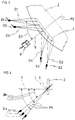
- Figure 1 shows schematically in profile view a first example of a mode of realization of the geometry of the lighting and observation means of a device according to the invention.
- Figure 2 shows schematically in front view along F2 the example illustrated on the Figure 1.
- Figure 3 schematically shows in top view according to F1 the example illustrated on Figure 1.
- Figure 4 shows schematically in profile view a second example of a realization of the geometry of the lighting means of a device according to the invention.
- Figure 5 is a schematic, functional, and partial representation in profile view of an exemplary embodiment of a device according to the invention comprising means lighting and observation means according to Figures 1, 2, and 3.
- Figure 6 shows a side view of an exemplary embodiment of a device according to the invention according to Figure 5.
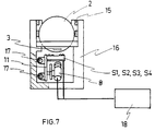
- Figure 7 shows in front view the exemplary embodiment of a device according to the invention according to Figure 6.
- the geometry of the lighting and observation means of the device according to the invention illustrated partially in FIG. 1 is shown in profile view parallel to a first plane P1, and in a position for identifying the characters 1 of a wafer-shaped substrate 2.
- the lighting means advantageously comprise a first S1, second S2, third S3, and fourth S4 light sources, provided in particular by means of four light-emitting diodes (LED).
- the four light sources S1, S2, S3, and S4 are placed substantially in the plane P1 passing through a minimal plane surface 3 which inscribes all the characters 1 of the substrate.
- the plane P1 defines a first angle ⁇ 1, advantageously of the order of 45 °, with a perpendicular 4 to the surface 3, and advantageously contains one of the largest axes of surface 3, as shown in Figure 1.
- the plate 2 is of a type commonly used in the electronic industry, in the form of thin disc on one side of which are engraved the identity characters of the plate in an area close to its circumference, as illustrated in Figure 2.
- the examples of plate 2 and characters 1 illustrated in the Figures are not to scale, are representative of those commonly encountered but in no way restrictive, all other character modes, for example example of bar codes, written on all other types of labels, which can be identified with the device according to the present invention.
- each of the first S1, second S2, third S3, and fourth S4 light sources is respectively located substantially on first D1, second D2, third D3, and fourth straight D4 passing through the surface 3 and forming in particular a second angle ⁇ 2, advantageously of the order of 45 °, with a second plane P2 perpendicular to the surface 3 and perpendicular to the foreground P1, as shown in Figure 3 which is a view along F1 of Figure 1 (view perpendicular to the foreground P1).
- the first S1 and third S3 light sources are advantageously respectively symmetrical of the second S2 and fourth S4 light sources with respect to the second plane P2, as shown in Figures 2 and 3.
- the four light sources S1, S2, S3, and S4 direct their light beams, in particular conical, in the direction of characters 1, and are advantageously located at a distance substantially equal to the surface 3.
- the distance between the light sources from the second plane P2 is advantageously such that the light beams they emit are at least intersecting at the surface 3, for example as shown in Figures 2 and 3.
- Figures 1, 2, and 3 also illustrate the geometry of the observation means comprising advantageously an electronic camera 8 provided with an optical axis 9.
- the camera 8 observes characters 1 illuminated by the four light sources S1, S2, S3, and S4 along its axis optics 9 advantageously merged with the second plane P2 and forming a third angle ⁇ 3 with perpendicular 4 to surface 3, as shown in Figures 1, 2, and 3.
- the third angle ⁇ 3 is advantageously adjustable, in particular between the values of 40 ° and 60 °, like this will be described more fully with the help of Figures 5, 6, and 7.
- FIG. 4 A second example of an embodiment of the geometry of the lighting means of the device according to the invention is illustrated schematically in Figure 4.
- the lighting means comprise a plurality of light sources Sn located in a plurality of planes Pn passing by said surface 3 and defining a plurality of respective angles ⁇ n, advantageously of about 45 °, with a perpendicular 4 to the surface 3.
- Each of the planes of the plurality of planes Pn is advantageously arranged in a similar manner to that described in FIGS. 1, 2, and 3, as well as each of the light sources of the plurality of light sources Sn in each plans.
- Figure 5 illustrates an example of the kinematics of the lighting means and the means of observation advantageously having the geometry described according to Figures 1, 2, and 3 of an exemplary embodiment of a device according to the invention.
- the plates 2 are stationary and arranged so that the identity characters that they carry are aligned, the surfaces 3 being substantially parallel, as will be described later with Figures 6 and 7.
- the four light sources S1, S2, S3, and S4 are fixed on a support 11 advantageously movable, relative to the plates, in translation in a direction 12 parallel to a perpendicular 4 to the flat surfaces 3.
- the camera 8 is fixed on the support 11 advantageously so as to be able to move in translation relative to to the latter in a direction 14 parallel to its optical axis 9 and also in rotation by relative to the support 11 substantially around the axis of greatest length of the surface 3, along a direction 13.
- the translational movement of the support 11 in the direction 12 allows the lighting and the observation of the characters of each plate
- the movement of the camera 8 in translation following direction 14 allows an optimization of the observation
- the movement of the camera 8 in rotation in direction 13 makes it possible to adjust the observation in particular as a function of the interval 10 separating each plate, by an appropriate adjustment of the third angle ⁇ 3.
- the lighting and observation means are advantageously designed to act by being placed under the pads, the pads remaining stationary for throughout the identification process, according to the invention, of all the platelets. This immobility of the plates and the positioning below them of the lighting means and observation means make it possible in particular to minimize the particulate contamination of platelets.
- Figures 6 and 7 show respectively in side view and in front view a example of embodiment of the device according to the invention according to FIG. 5.
- the device comprises means for positioning the plates 2 including, a structure 16 able to advantageously maintain in a horizontal position a basket 15 comprising the plates 2 each arranged vertically one behind the other in a groove at an interval regular variable according to the format of the plates, and a mechanism (not shown) for angularly orient all the plates 2 around their axis of alignment advantageously so that the identity characters of each plate are aligned in the position the lower compared to basket 15, as shown in Figure 7.
- the mechanism angular orientation of platelets is a known mechanism commonly encountered allowing to align the notches or flats (not shown) that the plates bear on their circumferences.
- This mechanism is advantageously placed inside the structure 16 and below the basket 15, and can advantageously be controlled from a central unit 18, which allows the possibility of automatic control of said mechanism.
- the device also includes lighting means and observation means advantageously as defined in Figures 1, 2, 3, and 5.
- the support 11 is for example guided in translation along two guide bars 17 parallel to an alignment axis of the platelets.
- the guides in translation and in rotation of the camera 8 relative to the support 11 are provided in any known way, for example by slide systems (not shown), and the movements of the camera 8 relative to the support 11 are in particular carried out manually.
- the position of the camera 8 relative to the support 11 is adjusted before a process identification.
- the movements of the support 11 are advantageously motorized (not shown) anyway known, and controllable through the central unit 18 of so as to ensure the possibility of automatic control of the movements of the lighting means and observation.
- the operations of the camera 8 and of the light sources S1, S2, S3, and S4 are advantageously controllable via the central unit 18, so as to ensure the possibility of complete automatic control of the lighting means and observation and / or monitoring of the identification of characters through a monitor (not shown).
- the device also includes means for identifying the characters based of the image observed and advantageously transmitted by the camera 8 to the latter, including in particular image processing software, and network character recognition software of neurons.
- the image processing software advantageously makes it possible to rough the transmitted image, and neural network recognition software advantageously allows an operator to visualize and identify the characters, for example through a monitor (not represented).
- Neural network recognition software also converts an image transmitted in information suitable for being processed by computer processing on network.
- the central unit is advantageously provided a platelet identification cycle management software adapted as needed to a process step or to a specific manufacturing process.
- the device according to the invention thus offers the possibility of fully automatic piloting.
- Neural network recognition software notably brings an advantage of speed character recognition therefore a productivity gain, and a rate of identification errors low characters therefore a low rate of manufacturing rejects.
- the means for positioning the plates and the lighting means and observation of the characters of the device according to the invention are inserted in a volume relatively compact, in particular due to the immobility of the platelets during the identification processes and due to the integration of the lighting means, observation means, and the platelet orientation mechanism below the basket. Intensive use of materials plastics makes it possible to obtain a weight of less than 15 kg which allows movement and easy transport. Finally, IT integration allows the device to be used according to the invention in communication with a network.
Landscapes
- Engineering & Computer Science (AREA)
- Physics & Mathematics (AREA)
- General Physics & Mathematics (AREA)
- Theoretical Computer Science (AREA)
- Artificial Intelligence (AREA)
- Computer Vision & Pattern Recognition (AREA)
- Multimedia (AREA)
- Electromagnetism (AREA)
- Health & Medical Sciences (AREA)
- General Health & Medical Sciences (AREA)
- Toxicology (AREA)
- Character Input (AREA)
- Investigating Materials By The Use Of Optical Means Adapted For Particular Applications (AREA)
- Image Processing (AREA)
- Image Analysis (AREA)
- Image Input (AREA)
- Devices For Indicating Variable Information By Combining Individual Elements (AREA)
Description
- éclairer de manière directe lesdits caractères au moyen d'au moins une première source lumineuse située dans un premier plan passant par une surface plane minimale qui inscrit la totalité desdits caractères et définissant un premier angle avec une perpendiculaire à ladite surface plane, ladite première source lumineuse étant située sur une droite passant par ladite surface plane et formant un deuxième angle avec un deuxième plan perpendiculaire à ladite surface plane et perpendiculaire audit premier plan,
- observer lesdits caractères avec des moyens d'observation électroniques comprenant un axe optique au moins parallèle audit deuxième plan et déterminant un troisième angle avec ladite perpendiculaire à ladite surface plane, ledit axe optique formant avec ledit plan un angle inférieur ou égal à 25°,
- identifier lesdits caractères au moins avec un logiciel de reconnaissance à réseaux de neurones, et
- déplacer au moins la source lumineuse et lesdits moyens d'observation électroniques en translation parallèlement à un axe d'alignement de ladite pluralité des substrats, pour les placer en position d'identification d'un deuxième substrat.
Claims (14)
- Procédé d'identification de caractères, gravés sur une pluralité de substrats disposés verticalement et immobiles, caractérisé en ce qu' il comporte au moins les étapes suivantes :éclairer de manière directe les caractères (1) d'un premier substrat (2) de ladite pluralité de substrats au moyen d'au moins une première source lumineuse (S1), ladite première source lumineuse (S1) étant située au dessous de ladite pluralité de substrats, ladite première source lumineuse (S1) étant située dans un premier plan (P1) passant par une surface (3) plane minimale qui inscrit la totalité desdits caractères dudit premier substrat et définissant un premier angle (β1) avec une perpendiculaire (4) à ladite surface plane, ladite première source lumineuse étant située sur une droite (D1) passant par ladite surface plane et formant un deuxième angle (β2) avec un deuxième plan (P2) perpendiculaire à ladite surface plane et perpendiculaire audit premier plan (P1),observer lesdits caractères avec des moyens d'observation (8) électroniques, lesdits moyens d'observation électroniques étant situés au dessous de ladite pluralité de substrats, lesdits moyens d'observation électroniques comprenant un axe optique (9) au moins parallèle audit deuxième plan (P2) et déterminant un troisième angle (β3) avec ladite perpendiculaire (4) à ladite surface (3) plane, ledit axe optique (9) formant avec ledit premier plan (P1) un angle inférieur ou égal à 25°,identifier lesdits caractères dudit premier substrat au moins avec un logiciel de reconnaissance à réseaux de neurones, etdéplacer au moins ladite première source lumineuse et lesdits moyens d'observation en translation parallèlement à un axe d'alignement de ladite pluralité des substrats, pour les placer en position d'identification des caractères d'un deuxième substrat de ladite pluralité de substrats.
- Procédé selon la Revendication 1, caractérisé en ce que ledit premier angle (β1) est compris entre 35° et 65°, et de préférence égal à 45°.
- Procédé selon la Revendication 1 ou 2, caractérisé en ce que ledit deuxième angle (β2) est compris entre 35° et 65°, et de préférence égal à 45°.
- Procédé selon l'une quelconque des Revendications 1 à 3, caractérisé en ce que ledit troisième angle (β3) est compris entre 40° et 60°, et de préférence égal à 48°.
- Procédé selon l'une quelconque des Revendications 1 à 4, caractérisé en ce que l'on éclaire lesdits caractères (1) au moyen d'au moins une deuxième source lumineuse (S2) symétrique à ladite première source lumineuse (S1) par rapport audit deuxième plan (P2).
- Procédé selon l'une quelconque des Revendications 1 à 5, caractérisé en ce que l'on éclaire lesdits caractères au moyen d'une pluralité de sources lumineuses (Sn) située dans une pluralité de plans (Pn) passant par ladite surface (3) plane et définissant une pluralité d'angles respectifs (βn) avec une perpendiculaire (4) à ladite surface plane.
- Dispositif d'identification de caractères (1), gravés sur des substrats (2), comprenant des moyens de positionnement desdits substrats, des moyens d'éclairage desdits caractères, des moyens d'observation desdits caractères, des moyens d'identification desdits caractères, caractérisé en ce que lesdits moyens de positionnement comprennent un panier (15) apte à maintenir lesdits substrats en position verticale et immobile, lesdits moyens de positionnement définissant au moins une surface (3) plane minimale apte à inscrire la totalité desdits caractères d'un substrat, en ce que lesdits moyens d'éclairage comprennent au moins une première source lumineuse (S1) située dans un premier plan (P1) passant par ladite surface (3) plane minimale et définissant un premier angle (β1) avec une perpendiculaire (4) à ladite surface plane, ladite première source lumineuse étant située sur une droite (D1) passant par ladite surface plane et formant un deuxième angle (β2) avec un deuxième plan (P2) perpendiculaire à ladite surface plane et perpendiculaire audit premier plan, en ce que lesdits moyens d'observation comprennent une caméra (8) électronique transmettant au moins une image auxdits moyens d'identification et comprenant un axe optique (9) au moins parallèle audit deuxième plan, déterminant un troisième angle (β3) avec ladite perpendiculaire (4) à ladite surface (3) plane, et formant avec ledit premier plan un angle inférieur ou égal à 25°, et en ce que ledit dispositif comprend des moyens de déplacement (11, 17) en translation desdits moyens d'éclairage et desdits moyens d'observation parallèlement à un axe d'alignement desdits substrats.
- Dispositif selon la Revendication 7, caractérisé en ce que ledit premier angle (β1) est compris entre 35° et 65°, et de préférence égal à 45°.
- Dispositif selon selon la Revendication 7 ou 8, caractérisé en ce que ledit deuxième angle (β2) est compris entre 35° et 65°, et de préférence égal à 45°.
- Dispositif selon l'une quelconque des Revendications 7 à 9, caractérisé en ce que ledit troisième angle (β3) est compris entre 40° et 60°, et de préférence égal à 48°.
- Dispositif selon l'une quelconque des Revendications 7 à 10, caractérisé en ce que lesdits moyens d'éclairage comprennent au moins une deuxième source lumineuse (S2) symétrique à ladite première source lumineuse (S1) par rapport audit deuxième plan (P2).
- Dispositif selon l'une quelconque des Revendications 7 à 11, caractérisé en ce qu' il comprend une pluralité de sources lumineuses (Sn) située dans une pluralité de plans (Pn) passant par ladite surface (3) plane et définissant une pluralité d'angles respectifs (βn) avec une perpendiculaire (4) à ladite surface plane.
- Dispositif selon l'une quelconque des Revendications 7 à 12, caractérisé en ce que lesdits moyens de positionnement, lesdits moyens d'éclairage et lesdits moyens d'observation au moins s'étendent au dessous desdits substrats (2).
- Dispositif selon l'une quelconque des Revendications 7 à 13, caractérisé en ce que lesdits moyens d'identification desdits caractères comprennent au moins un logiciel de reconnaissance à réseaux de neurones pour interpréter les images transmises par lesdits moyens d'observation.
Applications Claiming Priority (3)
| Application Number | Priority Date | Filing Date | Title |
|---|---|---|---|
| FR9312770 | 1993-10-21 | ||
| FR9312770A FR2711824B1 (fr) | 1993-10-21 | 1993-10-21 | Procédés et dispositifs d'identification de caractères inscrits sur des substrats. |
| PCT/FR1994/001228 WO1995011491A1 (fr) | 1993-10-21 | 1994-10-21 | Procedes et dispositifs d'identification de caracteres inscrits sur des substrats |
Publications (2)
| Publication Number | Publication Date |
|---|---|
| EP0724753A1 EP0724753A1 (fr) | 1996-08-07 |
| EP0724753B1 true EP0724753B1 (fr) | 1998-04-01 |
Family
ID=9452230
Family Applications (1)
| Application Number | Title | Priority Date | Filing Date |
|---|---|---|---|
| EP94931618A Expired - Lifetime EP0724753B1 (fr) | 1993-10-21 | 1994-10-21 | Procedes et dispositifs d'identification de caracteres inscrits sur des substrats |
Country Status (8)
| Country | Link |
|---|---|
| EP (1) | EP0724753B1 (fr) |
| JP (1) | JP3252327B2 (fr) |
| KR (1) | KR100346828B1 (fr) |
| AT (1) | ATE164697T1 (fr) |
| DE (1) | DE69409395T2 (fr) |
| ES (1) | ES2115266T3 (fr) |
| FR (1) | FR2711824B1 (fr) |
| WO (1) | WO1995011491A1 (fr) |
Families Citing this family (11)
| Publication number | Priority date | Publication date | Assignee | Title |
|---|---|---|---|---|
| FR2751769B1 (fr) * | 1996-07-29 | 1998-10-09 | Recif Sa | Procede et appareil d'identification de caracteres formes sur une pluralite de plaquettes de silicium |
| US7016539B1 (en) | 1998-07-13 | 2006-03-21 | Cognex Corporation | Method for fast, robust, multi-dimensional pattern recognition |
| FR2835337B1 (fr) | 2002-01-29 | 2004-08-20 | Recif Sa | Procede et dispositif d'identification de caracteres inscrits sur une plaque de semi-conducteur comportant au moins une marque d'orientation |
| US8081820B2 (en) | 2003-07-22 | 2011-12-20 | Cognex Technology And Investment Corporation | Method for partitioning a pattern into optimized sub-patterns |
| US7639861B2 (en) | 2005-09-14 | 2009-12-29 | Cognex Technology And Investment Corporation | Method and apparatus for backlighting a wafer during alignment |
| US9734419B1 (en) | 2008-12-30 | 2017-08-15 | Cognex Corporation | System and method for validating camera calibration in a vision system |
| US9533418B2 (en) | 2009-05-29 | 2017-01-03 | Cognex Corporation | Methods and apparatus for practical 3D vision system |
| US9393694B2 (en) | 2010-05-14 | 2016-07-19 | Cognex Corporation | System and method for robust calibration between a machine vision system and a robot |
| US9124873B2 (en) | 2010-12-08 | 2015-09-01 | Cognex Corporation | System and method for finding correspondence between cameras in a three-dimensional vision system |
| DE202012003661U1 (de) * | 2012-04-12 | 2013-07-15 | Mühlbauer Ag | Vorrichtung zum Erkennen von Codes |
| US9679224B2 (en) | 2013-06-28 | 2017-06-13 | Cognex Corporation | Semi-supervised method for training multiple pattern recognition and registration tool models |
Family Cites Families (3)
| Publication number | Priority date | Publication date | Assignee | Title |
|---|---|---|---|---|
| US3899687A (en) * | 1972-07-10 | 1975-08-12 | Identicon Corp | Optical label scanning |
| FR2594982A1 (fr) * | 1986-02-21 | 1987-08-28 | Eram Sarl Manuf Fse Chaussures | Mode de realisation de codes a lecture optique, procede de lecture desdits codes et installation pour la mise en oeuvre du procede |
| DE3742485A1 (de) * | 1987-12-15 | 1989-06-29 | Sick Optik Elektronik Erwin | Optische abtastvorrichtung |
-
1993
- 1993-10-21 FR FR9312770A patent/FR2711824B1/fr not_active Expired - Fee Related
-
1994
- 1994-10-21 JP JP51142395A patent/JP3252327B2/ja not_active Expired - Fee Related
- 1994-10-21 AT AT94931618T patent/ATE164697T1/de not_active IP Right Cessation
- 1994-10-21 KR KR1019960701383A patent/KR100346828B1/ko not_active Expired - Fee Related
- 1994-10-21 DE DE69409395T patent/DE69409395T2/de not_active Expired - Fee Related
- 1994-10-21 EP EP94931618A patent/EP0724753B1/fr not_active Expired - Lifetime
- 1994-10-21 ES ES94931618T patent/ES2115266T3/es not_active Expired - Lifetime
- 1994-10-21 WO PCT/FR1994/001228 patent/WO1995011491A1/fr not_active Ceased
Also Published As
| Publication number | Publication date |
|---|---|
| EP0724753A1 (fr) | 1996-08-07 |
| JPH09504892A (ja) | 1997-05-13 |
| ATE164697T1 (de) | 1998-04-15 |
| FR2711824A1 (fr) | 1995-05-05 |
| DE69409395T2 (de) | 1998-10-15 |
| KR960705282A (ko) | 1996-10-09 |
| ES2115266T3 (es) | 1998-06-16 |
| DE69409395D1 (de) | 1998-05-07 |
| KR100346828B1 (ko) | 2002-11-13 |
| FR2711824B1 (fr) | 1996-01-05 |
| WO1995011491A1 (fr) | 1995-04-27 |
| JP3252327B2 (ja) | 2002-02-04 |
Similar Documents
| Publication | Publication Date | Title |
|---|---|---|
| EP0401351B1 (fr) | Procede et dispositif de mesure optique | |
| WO1998044330A3 (fr) | Module d'inspection optique et methode de detection de particules ainsi que de defauts sur des substrats dans un appareillage de traitement integre | |
| EP1602001B1 (fr) | Dispositif optique et module d inspection | |
| WO1995011491A1 (fr) | Procedes et dispositifs d'identification de caracteres inscrits sur des substrats | |
| WO2011138524A1 (fr) | Dispositif et procede d'inspection de plaquettes semi-conductrices en mouvement | |
| EP0665951A1 (fr) | Procede et dispositif d'inspection de materiau transparent. | |
| DE10349694A1 (de) | Ausrichtungseinrichtung | |
| FR2874424A1 (fr) | Dispositif d'analyse optique de produits tels que des fruits a eclairage indirect | |
| EP0076182B1 (fr) | Procédé, appareil et utilisation permettant de faire un choix de colis parmi un lot de colis et de les manutentionner | |
| EP0086143A1 (fr) | Procédé et dispositif de détection de corps étrangers dans un liquide | |
| FR2562249A1 (fr) | Cellule humide tres radio-active, blindee, pour une installation nucleaire, avec un dispositif pour la reconnaissance des fuites et procede pour l'utilisation d'une telle cellule | |
| EP3728990A1 (fr) | Cible tridimensionnelle avec double structure, dispositif et procédé de mesure optique avec une telle cible | |
| EP1010126B1 (fr) | Procede et dispositif de lecture de reliefs portes par un recipient transparent ou translucide | |
| JP7208233B2 (ja) | ガラスシートの表面欠陥の検出方法および装置 | |
| CA2223263A1 (fr) | Dispositif de lecture de reliefs sur un recipient transparent | |
| FR2722573A1 (fr) | Procede et dispositif de reconnaissance de particularites geometriques de pieces parallelepipediques de section polygonale | |
| EP2981807B1 (fr) | Procede optique de caracterisation d'une surface diffractante et appareil pour la mise en uvre d'un tel procede | |
| CN1809744A (zh) | 用光学方法控制较佳的具有圆形边缘物件的质量的方法和装置 | |
| EP0857336B1 (fr) | Procede et appareil d'identification de caracteres formes sur une pluralite de plaquettes de silicium | |
| WO1997024607A1 (fr) | Appareil et procede de lecture de substrats | |
| WO1997024607A9 (fr) | Appareil et procede de lecture de substrats | |
| FR2538142A1 (fr) | Procede d'identification de produits metallurgiques et dispositif de mise en oeuvre | |
| EP2962085A1 (fr) | Procede et appareil de caracterisation d'une surface diffractante. | |
| FR3122008A1 (fr) | Dispositif d’éclairage d’une surface à contrôler | |
| FR2484099A1 (fr) | Procede et dispositif de reperage d'informations portees par une microfiche |
Legal Events
| Date | Code | Title | Description |
|---|---|---|---|
| PUAI | Public reference made under article 153(3) epc to a published international application that has entered the european phase |
Free format text: ORIGINAL CODE: 0009012 |
|
| 17P | Request for examination filed |
Effective date: 19960410 |
|
| AK | Designated contracting states |
Kind code of ref document: A1 Designated state(s): AT BE CH DE ES FR GB IE IT LI NL SE |
|
| GRAG | Despatch of communication of intention to grant |
Free format text: ORIGINAL CODE: EPIDOS AGRA |
|
| GRAG | Despatch of communication of intention to grant |
Free format text: ORIGINAL CODE: EPIDOS AGRA |
|
| GRAH | Despatch of communication of intention to grant a patent |
Free format text: ORIGINAL CODE: EPIDOS IGRA |
|
| 17Q | First examination report despatched |
Effective date: 19970905 |
|
| GRAH | Despatch of communication of intention to grant a patent |
Free format text: ORIGINAL CODE: EPIDOS IGRA |
|
| GRAA | (expected) grant |
Free format text: ORIGINAL CODE: 0009210 |
|
| AK | Designated contracting states |
Kind code of ref document: B1 Designated state(s): AT BE CH DE ES FR GB IE IT LI NL SE |
|
| REF | Corresponds to: |
Ref document number: 164697 Country of ref document: AT Date of ref document: 19980415 Kind code of ref document: T |
|
| REG | Reference to a national code |
Ref country code: CH Ref legal event code: EP |
|
| REF | Corresponds to: |
Ref document number: 69409395 Country of ref document: DE Date of ref document: 19980507 |
|
| REG | Reference to a national code |
Ref country code: ES Ref legal event code: FG2A Ref document number: 2115266 Country of ref document: ES Kind code of ref document: T3 |
|
| ITF | It: translation for a ep patent filed | ||
| REG | Reference to a national code |
Ref country code: CH Ref legal event code: NV Representative=s name: HUG INTERLIZENZ AG |
|
| GBT | Gb: translation of ep patent filed (gb section 77(6)(a)/1977) |
Effective date: 19980622 |
|
| REG | Reference to a national code |
Ref country code: IE Ref legal event code: FG4D Free format text: 79637 |
|
| PLBE | No opposition filed within time limit |
Free format text: ORIGINAL CODE: 0009261 |
|
| STAA | Information on the status of an ep patent application or granted ep patent |
Free format text: STATUS: NO OPPOSITION FILED WITHIN TIME LIMIT |
|
| 26N | No opposition filed | ||
| REG | Reference to a national code |
Ref country code: GB Ref legal event code: IF02 |
|
| PGFP | Annual fee paid to national office [announced via postgrant information from national office to epo] |
Ref country code: GB Payment date: 20041018 Year of fee payment: 11 |
|
| PGFP | Annual fee paid to national office [announced via postgrant information from national office to epo] |
Ref country code: DE Payment date: 20041020 Year of fee payment: 11 |
|
| PGFP | Annual fee paid to national office [announced via postgrant information from national office to epo] |
Ref country code: NL Payment date: 20041021 Year of fee payment: 11 Ref country code: CH Payment date: 20041021 Year of fee payment: 11 |
|
| PGFP | Annual fee paid to national office [announced via postgrant information from national office to epo] |
Ref country code: SE Payment date: 20041022 Year of fee payment: 11 Ref country code: AT Payment date: 20041022 Year of fee payment: 11 |
|
| PGFP | Annual fee paid to national office [announced via postgrant information from national office to epo] |
Ref country code: IE Payment date: 20041027 Year of fee payment: 11 Ref country code: ES Payment date: 20041027 Year of fee payment: 11 |
|
| PGFP | Annual fee paid to national office [announced via postgrant information from national office to epo] |
Ref country code: FR Payment date: 20041029 Year of fee payment: 11 |
|
| PGFP | Annual fee paid to national office [announced via postgrant information from national office to epo] |
Ref country code: BE Payment date: 20041117 Year of fee payment: 11 |
|
| PG25 | Lapsed in a contracting state [announced via postgrant information from national office to epo] |
Ref country code: IT Free format text: LAPSE BECAUSE OF NON-PAYMENT OF DUE FEES;WARNING: LAPSES OF ITALIAN PATENTS WITH EFFECTIVE DATE BEFORE 2007 MAY HAVE OCCURRED AT ANY TIME BEFORE 2007. THE CORRECT EFFECTIVE DATE MAY BE DIFFERENT FROM THE ONE RECORDED. Effective date: 20051021 Ref country code: IE Free format text: LAPSE BECAUSE OF NON-PAYMENT OF DUE FEES Effective date: 20051021 Ref country code: GB Free format text: LAPSE BECAUSE OF NON-PAYMENT OF DUE FEES Effective date: 20051021 Ref country code: AT Free format text: LAPSE BECAUSE OF NON-PAYMENT OF DUE FEES Effective date: 20051021 |
|
| PG25 | Lapsed in a contracting state [announced via postgrant information from national office to epo] |
Ref country code: SE Free format text: LAPSE BECAUSE OF NON-PAYMENT OF DUE FEES Effective date: 20051022 Ref country code: ES Free format text: LAPSE BECAUSE OF NON-PAYMENT OF DUE FEES Effective date: 20051022 |
|
| PG25 | Lapsed in a contracting state [announced via postgrant information from national office to epo] |
Ref country code: LI Free format text: LAPSE BECAUSE OF NON-PAYMENT OF DUE FEES Effective date: 20051031 Ref country code: CH Free format text: LAPSE BECAUSE OF NON-PAYMENT OF DUE FEES Effective date: 20051031 Ref country code: BE Free format text: LAPSE BECAUSE OF NON-PAYMENT OF DUE FEES Effective date: 20051031 |
|
| PG25 | Lapsed in a contracting state [announced via postgrant information from national office to epo] |
Ref country code: NL Free format text: LAPSE BECAUSE OF NON-PAYMENT OF DUE FEES Effective date: 20060501 |
|
| PG25 | Lapsed in a contracting state [announced via postgrant information from national office to epo] |
Ref country code: DE Free format text: LAPSE BECAUSE OF NON-PAYMENT OF DUE FEES Effective date: 20060503 |
|
| REG | Reference to a national code |
Ref country code: CH Ref legal event code: PL |
|
| EUG | Se: european patent has lapsed | ||
| GBPC | Gb: european patent ceased through non-payment of renewal fee |
Effective date: 20051021 |
|
| PG25 | Lapsed in a contracting state [announced via postgrant information from national office to epo] |
Ref country code: FR Free format text: LAPSE BECAUSE OF NON-PAYMENT OF DUE FEES Effective date: 20060630 |
|
| NLV4 | Nl: lapsed or anulled due to non-payment of the annual fee |
Effective date: 20060501 |
|
| REG | Reference to a national code |
Ref country code: IE Ref legal event code: MM4A |
|
| REG | Reference to a national code |
Ref country code: FR Ref legal event code: ST Effective date: 20060630 |
|
| REG | Reference to a national code |
Ref country code: ES Ref legal event code: FD2A Effective date: 20051022 |
|
| BERE | Be: lapsed |
Owner name: S.A. *RECIF Effective date: 20051031 |