EP0724693B1 - Dispositif d'étanchéité - Google Patents
Dispositif d'étanchéité Download PDFInfo
- Publication number
- EP0724693B1 EP0724693B1 EP94929484A EP94929484A EP0724693B1 EP 0724693 B1 EP0724693 B1 EP 0724693B1 EP 94929484 A EP94929484 A EP 94929484A EP 94929484 A EP94929484 A EP 94929484A EP 0724693 B1 EP0724693 B1 EP 0724693B1
- Authority
- EP
- European Patent Office
- Prior art keywords
- sealing ring
- groove
- pressure side
- sealing
- peripheral surface
- Prior art date
- Legal status (The legal status is an assumption and is not a legal conclusion. Google has not performed a legal analysis and makes no representation as to the accuracy of the status listed.)
- Expired - Lifetime
Links
- 238000007789 sealing Methods 0.000 title claims abstract description 228
- 230000002093 peripheral effect Effects 0.000 claims abstract description 37
- 230000004323 axial length Effects 0.000 claims description 8
- 239000007787 solid Substances 0.000 claims description 8
- 239000012530 fluid Substances 0.000 description 7
- 230000033001 locomotion Effects 0.000 description 4
- 239000000463 material Substances 0.000 description 4
- 230000003068 static effect Effects 0.000 description 4
- 239000013013 elastic material Substances 0.000 description 3
- 230000000717 retained effect Effects 0.000 description 3
- 230000018109 developmental process Effects 0.000 description 2
- 230000036316 preload Effects 0.000 description 2
- 230000008602 contraction Effects 0.000 description 1
- 230000007423 decrease Effects 0.000 description 1
- 238000001125 extrusion Methods 0.000 description 1
- 238000009434 installation Methods 0.000 description 1
- 230000008092 positive effect Effects 0.000 description 1
- 230000006641 stabilisation Effects 0.000 description 1
- 238000011105 stabilization Methods 0.000 description 1
Images
Classifications
-
- F—MECHANICAL ENGINEERING; LIGHTING; HEATING; WEAPONS; BLASTING
- F16—ENGINEERING ELEMENTS AND UNITS; GENERAL MEASURES FOR PRODUCING AND MAINTAINING EFFECTIVE FUNCTIONING OF MACHINES OR INSTALLATIONS; THERMAL INSULATION IN GENERAL
- F16J—PISTONS; CYLINDERS; SEALINGS
- F16J15/00—Sealings
- F16J15/16—Sealings between relatively-moving surfaces
- F16J15/32—Sealings between relatively-moving surfaces with elastic sealings, e.g. O-rings
- F16J15/3204—Sealings between relatively-moving surfaces with elastic sealings, e.g. O-rings with at least one lip
- F16J15/3232—Sealings between relatively-moving surfaces with elastic sealings, e.g. O-rings with at least one lip having two or more lips
- F16J15/3236—Sealings between relatively-moving surfaces with elastic sealings, e.g. O-rings with at least one lip having two or more lips with at least one lip for each surface, e.g. U-cup packings
-
- F—MECHANICAL ENGINEERING; LIGHTING; HEATING; WEAPONS; BLASTING
- F16—ENGINEERING ELEMENTS AND UNITS; GENERAL MEASURES FOR PRODUCING AND MAINTAINING EFFECTIVE FUNCTIONING OF MACHINES OR INSTALLATIONS; THERMAL INSULATION IN GENERAL
- F16J—PISTONS; CYLINDERS; SEALINGS
- F16J15/00—Sealings
- F16J15/16—Sealings between relatively-moving surfaces
- F16J15/32—Sealings between relatively-moving surfaces with elastic sealings, e.g. O-rings
- F16J15/3204—Sealings between relatively-moving surfaces with elastic sealings, e.g. O-rings with at least one lip
Definitions
- the invention relates to a rubber-elastic sealing ring between two concentric machine parts moving towards each other, which the sealing ring in one to the second machine part open, consisting of a groove base and groove flanks Keep the groove of the first machine part arranged by the Sealing ring with a dynamic sealing edge on one on the second Machine part trained peripheral surface that with a starting from the dynamic sealing edge and extending to the low pressure side N first surface forms the first wedge gap, the sealing ring with a Groove-supporting outer peripheral surface on the low pressure side N opening second wedge gap that Sealing ring orthogonal to the longitudinal axis of the second machine part and the dynamic sealing edge cutting first Defined level over which a separated by an incision first and a second sealing ring section to the high pressure side H project directed, the first sealing ring section is bounded by at least one area that ends ends in the dynamic sealing edge, and the second Sealing ring section over the first sealing ring section in Protrudes towards the high pressure side H and from the outer peripheral surface and a fourth and fifth
- the sealing ring is on the low pressure side surrounded by a conical support ring.
- the Support ring takes on the sealing ring when pressurized acting forces largely so that the dynamic Sealing edge is relieved of pressure.
- a first wedge gap into which the sealing ring is drawn when pressure is applied becomes.
- the first wedge gap is therefore when pressurized closed.
- a second wedge gap is in the known Sealing ring provided on the bottom of the groove, the one at another Pressurization becomes zero and thereby the dynamic Relieved sealing edge.
- the contact pressure of the dynamic sealing edge to the adapt to the respective pressure and material conditions.
- the dynamic sealing edge is known by the reaction of the Sealing rings relieved of pressure on a pressure load, but one for the return behavior of a sealing ring necessary wedge gap is not formed.
- One to the low pressure side trained flat tapering pressure gradient is missing entirely. For these reasons, the dynamic Sealing edge destroyed by extrusion and the life of the Sealing rings are reduced.
- the invention is therefore based on the object, the known Seal arrangement to further develop that they too the gap between the machine parts when depressurized seals securely and improved when pressurized Has downtimes.
- a Line of intersection from a third and a fourth level, in which the outer peripheral surface and the first surface in the deformation-free Condition of the sealing ring lie in a room between the second plane and the peripheral surface of the second Machine part is that the sealing ring between the first Level and the low pressure side N formed as a solid is, and that the sealing ring in the groove installed, unpressurized Condition of an opening to the bottom of the groove and from the groove side on the low pressure side and an adjacent sealing ring surface formed third wedge gap.
- a solid is understood to be a section of material which is made without significant cuts and that Has deformation behavior of a block of material.
- the profile of the sealing ring according to the invention is designed such that the sealing ring is in a deformation-free state a second wedge gap in the area of the cutting line of the groove base and has the groove flank on the low pressure side.
- This second wedge gap is albeit to a reduced extent both when installed and when pressurized Condition of the sealing ring according to the invention obtained.
- the second wedge gap enables deflections in the operation of the Sealing rings in the formed by the second wedge gap Free space.
- the sealing ring according to the invention has non-pressurized condition a third wedge gap to the bottom of the groove.
- This third wedge gap is at pressurized closed.
- the third wedge gap enables deflections in the pressurized use of the Sealing rings in the formed by the third wedge gap Free space.
- An increasing pressure on the sealing ring leads to its rubber-elastic material properties to one Contraction of the sealing ring in the axial direction and one Expansion of the sealing ring in the radial direction.
- the invention Sealing ring can deform in such a way because of deflections are possible in the second and third wedge gaps. The dynamic This can relieve pressure on the sealing edge.
- the tendency of sealing elements to extrude is also considerable improved.
- the sealing ring according to the invention thus has the essential Advantage that there is significant interference between Sealing ring and groove space when the sealing ring is installed is degraded in such a way that no increased contact pressure on the dynamic sealing edge is created.
- the sealing ring thus points lower friction values compared to known sealing rings. This results in reduced wear and increased Downtimes are the result.
- the first wedge gap to the low pressure side N in the area of dynamic sealing edge is in a direct operative connection with the second wedge gap in the groove base area.
- Sealing ring in the area of the first and second Wedge gap corresponding forces.
- the active connection between the first and the second wedge gap is by the Alignment of the outer peripheral surface and the first surface of the Sealing rings to each other. The alignment is through the position of the intersection of the defined third and fourth Level and the third wedge gap determined.
- Sealing rings in the installed state are made by material deformation in the sealing ring profile essentially before Sealing edge, so that it is guaranteed that in the low pressure range of the sealing ring in the area behind the sealing edge almost no preload forces act in the radial direction.
- the degree of deformation of the sealing ring according to the invention in built-in and pressurized can also can be influenced by the selection of the elastic material.
- An incision in the sealing ring according to the invention separates two Sealing ring sections towards the high pressure side H.
- the incision performs the function of a hinge under pressure, that open with more or less heavy load or can close.
- Such a sealing ring can be used as so-called check valve fluid safely from the low pressure side Transport to the high pressure side when the fluid on the low pressure side N is under a greater pressure than the fluid on the high pressure side H.
- the sealing ring forms in the installed condition with the low-pressure side groove flank a second wedge gap that opens towards the bottom of the groove Area of application for sealing rings in the low pressure range has greater radial extension than in the area of application for sealing rings in the high pressure area.
- the sealing ring is in the pressurized condition in the corner area of Nutgrin and groove side on the low-pressure side spaced from the groove base.
- Sealing ring has the third sealing ring Wedge gap when installed, depressurized due to a Deformation on.
- the sealing ring according to the invention is pivoted during installation, in which he is pressed against the low-pressure side of the groove becomes.
- the sealing ring can be in one section form the third wedge gap, which is towards the bottom of the groove opens.
- the free space on the low pressure side becomes like it is determined by the second wedge gap when installing the Sealing rings automatically enlarged and under pressure can the sealing ring according to the invention this space fill in by pressure in this space more or less pressed in. This is a sealing ring created, the stronger with increased fluid pressure depending on the dimensions can be relieved of pressure.
- the full body of the sealing ring in the deformation-free State has an axial length that is greater than is 2.2 times the length of the second sealing ring section, and the sealing ring has one to the longitudinal axis in the finished state of the second machine part inclined sealing ring surface on in the installed and depressurized state of the Sealing rings with the low-pressure side groove flank the third Wedge gap defined.
- Sealing rings of this length according to the invention are due to their Torsional stiffness no longer able to pivot, to form a third wedge gap on the low pressure side. Due to the inclined sealing ring surface even in these embodiments, which are rectangular Groove can be installed, a third wedge gap.
- the sealing ring according to the invention shows the full body part of the sealing ring that the Exceeds 2.2 times the axial length of the second sealing ring section, a second outer circumferential surface that with the Grooves an angle that is smaller than that Angle between the first outer peripheral surface and the groove base.
- the pressurized Sealing ring with a larger contact surface create the groove flank on the low pressure side and the groove base.
- the contact behavior of the sealing ring in the static sealing area is therefore stabilized.
- Securing the static Sealing also has a positive effect on stabilization the pressure distribution of the sealing ring, especially on the dynamic sealing edge, off.
- the individual figures of the drawing show the invention Item highly schematic and are not to scale to understand.
- the individual proportions of the sealing ring can be different as long as it is guaranteed that the manufactured sealing ring is an oversize to the intended groove has on the high pressure side H, the low pressure side merges into an undersize.
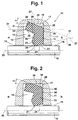
- Fig. 1 shows a sealing arrangement 10, which consists of a first Machine part 11, a second machine part 12 and there is a sealing ring 13.
- the concentric machine parts 11, 12 can move towards each other. That is, the machine parts a rotation or an outward movement and perform locomotion.
- a groove 14 is formed in the first machine part 11, the to a peripheral surface 15 of the second machine part 11 opens.
- the groove 14 itself is from a high pressure side Groove edge 16, a low pressure side groove edge 17 and one Groove bottom 18 formed.
- the machine parts 11, 12 are spaced from each other via a gap 19.
- the sealing ring 13 has an axis of rotation that the Longitudinal axis 20 (axis of symmetry) of the second machine part 12 corresponds.
- a dynamic sealing edge 21 of the sealing ring 13 is the intersection of a first surface 22 and one second surface 23 is formed. It is understood that the second surface 23 also extend to the step in the sealing ring 13 can.
- the groove bottom 18 is on the Sealing ring 13 has an outer peripheral surface 25 formed in Area of a static seal on the groove base 18 is present.
- Fig. 1 the sealing ring 13 is in a completely relieved Condition shown how it is made.
- the sealing ring 13 is assigned to a groove 14 in FIG. 1, the Groove base 18 is drawn in dashed lines, so that the outer contour of the sealing ring 13 in the finished state without tension can be shown. 1 is interference recognize, that is, the sealing ring 13 has an excess the groove 14 on.
- the sealing ring 13 also has two over an incision 26 separate and via a first level 27 to the high pressure side H protruding sealing ring sections 28, 29.
- the first Level 27 runs perpendicular to the longitudinal axis 20 through the Sealing edge 21.
- the first sealing ring section 28 is through the second surface 23 and a third surface 30 delimit.
- Of the second sealing ring section 29 is through a fourth surface 31 and a fifth surface 32 bounded.
- the fourth surface 31 and the fifth surface 32 intersect in an intersection line 33 and form a paragraph.
- the intersection line 33 defines a second plane 34 that is parallel to the longitudinal axis 20 runs through the section line 33.
- the outer peripheral surface 25 lies in a third level 35, the fourth Level 36 has a section line 37 in common.
- the fourth level 36 is determined in that the first surface 22nd lies.
- the intersection line 33 lies in a space that is from the Circumferential surface 15 and the second level 34 is limited.
- the oversize which is formed in the area of the intersection of the outer peripheral surface 25 and the high-pressure side fourth area 31, ends in the area of the dynamic sealing edge 21.
- the sealing ring 13 is made with an undersize, ie a second wedge gap 38 is formed in the area of the groove base 18 and the groove flank 17 on the low-pressure side.
- the sealing ring 13 itself is manufactured in such a way that it bears with a radially extending sealing ring surface 39 on the low-pressure side groove flank 17.
- Fig. 2 shows a cross section of the sealing ring 13 in the installed state between the machine parts 11, 12.
- the sealing ring 13 lies over the dynamic sealing edge 21 on the peripheral surface 15 of the second machine part 12.
- the sealing ring 13 is prestressed in the groove 14 that the sealing ring 13 is deformed such that an angle ⁇ 2 between the longitudinal axis 20 and the outer circumferential surface 25 is established, which is smaller than the angle ⁇ 1 , as shown in FIG. 1.
- the second wedge gap 38 is retained even after the sealing ring 13 has been installed.
- a third wedge gap 40 is formed between the groove flank 17 on the low pressure side and the sealing ring surface 39 of the sealing ring 13 adjoining it.
- the first wedge gap 24 is also formed in the installed position.
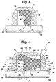
- Fig. 3 shows the sealing ring 13 of Fig. 1 and Fig. 2 in pressurized condition.
- H is the high pressure side marked and with N the low pressure side is marked.
- the sealing ring 13 faces H from the high pressure side seen from the incision 26, which is under pressure acts as a hinge.
- the sealing ring 13 is under Pressure pressed into the free space that the second and third Limit wedge gap 38, 40.
- By deflecting the sealing ring 13 the sealing edge 21 is relieved. Even under pressure is both the first wedge gap 24 as well the second wedge gap 38 is formed. Under pressure close the third wedge gap 40 so that the Sealing ring surface 39 on the low-pressure side groove flank 17 creates.
- Fig. 4 shows a sealing arrangement 50, which consists of a first Machine part 51, a second machine part 52 and there is a sealing ring 53.
- the concentric machine parts 51, 52 can move towards each other. That is, the machine parts a rotation or an outward movement and perform locomotion.
- a groove 54 is formed in the first machine part 51, the opens to the peripheral surface 55 of the second machine part 52.
- the groove 54 itself is made up of a groove flank on the high pressure side 56, a low pressure side groove flank 57 and one Groove bottom 58 formed.
- the machine parts 51, 52 are over a gap 59 spaced apart.
- the sealing ring 53 has an axis of rotation that the Longitudinal axis 60 (axis of symmetry) of the second machine part 52 corresponds.
- a dynamic sealing edge 61 of the sealing ring 53 is the intersection of a first surface 62 and one second surface 63 is formed. It is understood that the second surface 63 also extend to the step in the sealing ring 53 can.
- the groove base 58 is on the Sealing ring 53 formed a first outer peripheral surface 65, those in the area of a static seal on the groove base 58 is present.
- the sealing ring 53 is in a completely relieved Condition shown how it is made.
- the sealing ring 53 is assigned to a groove 54 in FIG. 4, the Groove base 58 is drawn in dashed lines, so that the outer contour of the sealing ring 53 in the finished state without tension can be shown. 4 there is interference recognize, that is, the sealing ring 53 has an excess the groove 54.
- the sealing ring 53 also has two over an incision 66 separate and via a first level 67 to the high pressure side H protruding sealing ring sections 68, 69.
- the first Level 67 runs perpendicular to the longitudinal axis 60 through the Sealing edge 61.
- the first sealing ring section 68 is through the second surface 63 and a third surface 70 delimit.
- Of the second sealing ring section 69 is through a fourth surface 71 and a fifth surface 72 bounded.
- the fourth surface 71 and the fifth surface 72 intersect in an intersection line 73 and form a paragraph.
- the intersection line 73 defines a second plane 74 that is parallel to the longitudinal axis 60 runs through the section line 73.
- the first outer peripheral surface 65 lies in a third level 75, which with a fourth plane 76 has a section line 77 in common.
- the fourth level 76 is determined by the fact that the first Area 62 lies.
- the intersection line 77 lies in a room which is bounded by the peripheral surface 55 and the second plane 74 becomes.
- the first outer peripheral surface 65 which adjoins the high-pressure side fourth surface 71 of the sealing ring 53, is inclined with respect to the longitudinal axis 60, the longitudinal axis 60 defining an angle ⁇ 1 with the first outer peripheral surface 65.
- the oversize which is formed in the area of the intersection of the first outer peripheral surface 65 and the high-pressure side fourth surface 71, ends in the area of the dynamic sealing edge 61.
- the sealing ring 53 is made with an undersize, ie, a second wedge gap 78 is formed in the area of the groove base 58 and the groove flank 57 on the low-pressure side.
- a second outer peripheral surface 79 of the sealing ring 53 forms an angle with the groove base 58 that is smaller than the angle between the first outer peripheral surface 65 and the groove base 58.
- the sealing ring 53 itself is made such that it with a inclined sealing ring surface 80 on the low pressure side Groove flank 57 bears in such a way that it is deformation-free State of the sealing ring 53, a third wedge gap 81 forms.
- the wedge gap 81 is from the groove flank 57 and the Sealing ring area 80 limited.
- the third wedge gap 81 will closed with increasing pressure, so that the Sealing ring surface 80 with its entire radial length on the groove side 57 on the low-pressure side comes to rest.
- a sealing ring 13 between two mutually movable concentric machine parts 11, 12 is made of a rubber-elastic material and it is inserted into a groove 14 which, starting from the first machine part 11, is open towards the second machine part 12.
- the sealing ring 13 is larger than the groove 14, in which the sealing ring 13 is to be installed, which is formed in the area of the sealing ring 13 on the high-pressure side.
- the sealing ring 13 is made with undersize.
- the outer circumferential surface 25 opposite the groove base 18 has an angle ⁇ 1 with respect to a longitudinal axis 20, which angle decreases to an angle ⁇ 2 in the installed position of the sealing ring 13.
- a second wedge gap 38 which is formed in the installed state of the sealing ring 13 in the region of the low-pressure side groove flank 17 and the groove base 18, is also retained in the pressure-loaded state of the sealing ring 13. Between the peripheral surface 15 of the second machine part 12 and the sealing ring 13, a first wedge gap 24 is formed on the low pressure side, which is retained even under pressure.
Landscapes
- General Engineering & Computer Science (AREA)
- Engineering & Computer Science (AREA)
- Mechanical Engineering (AREA)
- Sealing Devices (AREA)
- Glass Compositions (AREA)
- Sealing Battery Cases Or Jackets (AREA)
- Materials For Medical Uses (AREA)
- Gasket Seals (AREA)
- Sealing With Elastic Sealing Lips (AREA)
- Separation By Low-Temperature Treatments (AREA)
- Manufacturing Of Electric Cables (AREA)
- Electrical Discharge Machining, Electrochemical Machining, And Combined Machining (AREA)
- Vehicle Body Suspensions (AREA)
- Seal Device For Vehicle (AREA)
- Diaphragms For Electromechanical Transducers (AREA)
- Springs (AREA)
- Diaphragms And Bellows (AREA)
Claims (7)
- Bague d'étanchéité (13 ; 53) présentant l'élasticité du caoutchouc, entre deux parties de machines concentriques (11, 12 ; 51, 52), qui se déplacent l'une par rapport à l'autre, lesdites parties retenant la bague d'étanchéité (13 ; 53) dans une gorge (14 ; 54) de la première partie de machine (11 ; 51), ouverte en direction de la seconde partie de machine (12 ; 52) et constituée par un fond de gorge (18 ; 58) et par des flancs de gorge (16, 17 ; 56, 57), du fait que la bague d'étanchéité (13 ; 53) s'applique par une arête d'étanchéité dynamique (21 ; 61) contre une surface périphérique (15 ; 55) réalisée sur la seconde partie de machine (12 ; 52), ladite surface périphérique (15 ; 55) formant avec une première surface (22 ; 62) qui part de l'arête d'étanchéité dynamique (21 ; 61) et s'étend jusqu'au côté basse pression (N), une première fente en coin (24 ; 64), la bague d'étanchéité (13 ; 53) formant avec une surface périphérique extérieure (25 ; 65) qui s'appuie contre le fond (18 ; 58) de la gorge, une seconde fente en coin (38 ; 78) qui s'ouvre vers le côté basse pression (N), la bague d'étanchéité (13 ; 53) définissant un premier plan (27, 67) perpendiculaire à l'axe longitudinal (20 ; 60) de la seconde partie de machine (12 ; 52) et qui recoupe l'arête d'étanchéité dynamique (21 ; 61), au-delà duquel dépassent un premier et un second tronçon de bague d'étanchéité (28, 29 ; 68, 69) dirigés vers le côté haute pression (H) et séparés par une entaille (26 ; 66), le premier tronçon de bague d'étanchéité (28 ; 68) étant délimité par au moins une surface (22 , 23 ; 62, 63) qui se termine à une extrémité dans l'arête d'étanchéité dynamique (21 ; 61), et le second tronçon de bague d'étanchéité (29 ; 69) dépassant au-delà du premier tronçon de bague d'étanchéité (28 ; 68) en direction du côté haute pression (H), et étant formé par la surface périphérique extérieure (25 ; 65) et par une quatrième et une cinquième surface (31, 32, 71, 72) qui se recoupent et qui forment un talon, lesdites surfaces formant une ligne de coupe (33 ; 73) à distance du fond de gorge (18 ; 58), laquelle définit un second plan (34 ; 74) s'étendant parallèlement à l'axe longitudinal (20 ; 60),
caractériséeen ce qu'une ligne de coupe (37 ; 77) d'un troisième et d'un quatrième plan (35, 36 ; 75, 76), dans lesquels est située la surface périphérique extérieure (25 ; 65) et la première surface (22 ; 62) dans l'état déformé de la bague d'étanchéité (13 ; 53), est située dans un espace entre le second plan (34 ; 74) et la surface périphérique (15 ; 55) de la seconde partie de machine,en ce que la bague d'étanchéité (13 ; 53) est réalisée sous forme d'un corps plein entre le premier plan (27 ; 67) et le côté basse pression N,et en ce que la bague d'étanchéité (13 ; 53) présente, dans l'état sans pression monté dans la gorge (14 ; 54), une troisième fente en coin (40 ; 81) qui s'ouvre vers le fond de gorge (18 ; 58), et qui est formée par un flanc de gorge (17 ; 57) du côté basse pression et par une surface limitrophe (39 ; 80) de la bague d'étanchéité. - Bague d'étanchéité selon la revendication 1, caractérisée en ce que la troisième fente en coin (40 ; 81) présente dans le domaine d'application pour des bagues d'étanchéité dans la plage des basses pressions une étendue radiale supérieure à celle dans le domaine d'application pour des bagues d'étanchéité dans la plage des hautes pressions.
- Bague d'étanchéité selon l'une ou l'autre des revendications 1 et 2, caractérisé en ce que la bague d'étanchéité (13 ; 53) est, dans l'état mis sous pression, à distance du fond de gorge (18 ; 58) dans la région du coin du fond de gorge (18 ; 58) et du flanc de gorge côté basse pression (17 ; 57).
- Bague d'étanchéité selon l'une des revendications précédentes, caractérisée en ce que, dans l'état sans déformation, le corps plein de la bague d'étanchéité (13) présente une longueur axiale qui est limitée à 2,2 fois la longueur du second tronçon de bague d'étanchéité (29), et en ce que, dans l'état non déformé de la bague d'étanchéité (13), la surface annulaire d'étanchéité (39) s'étend parallèlement au flanc de gorge (17) côté basse pression.
- Bague d'étanchéité selon la revendication 4, caractérisée en ce que la bague d'étanchéité (13) présente la troisième fente en coin (40) dans l'état monté et sans pression en raison d'une déformation.
- Bague d'étanchéité selon l'une des revendications 1 à 3, caractérisée en ce que, dans l'état non déformé, le corps plein de la bague d'étanchéité (53) présente une longueur axiale qui est supérieure à 2,2 fois la longueur du second tronçon de bague d'étanchéité (69), et en ce que dans la situation finie, la bague d'étanchéité (53) présente une surface annulaire d'étanchéité (80) oblique vis-à-vis de l'axe longitudinal de la seconde partie de machine, qui définit, dans l'état monté et sans pression de la bague d'étanchéité (53), la troisième fente en coin (81) avec le flanc de gorge côté basse pression (57).
- Bague d'étanchéité selon la revendication 6, caractérisée en ce que la partie pleine du corps de la bague d'étanchéité (53), qui dépasse 2,2 fois la longueur axiale du second tronçon de bague d'étanchéité (69), présente une seconde surface périphérique extérieure (79) qui enferme avec le fond de gorge (58) un angle qui est inférieur à l'angle entre la première surface périphérique extérieure 65) et le fond de gorge (58).
Applications Claiming Priority (3)
| Application Number | Priority Date | Filing Date | Title |
|---|---|---|---|
| DE4335788 | 1993-10-20 | ||
| DE4335788A DE4335788A1 (de) | 1993-10-20 | 1993-10-20 | Dichtungsanordnung |
| PCT/DE1994/001231 WO1995011395A1 (fr) | 1993-10-20 | 1994-10-18 | Joint a levres |
Publications (2)
| Publication Number | Publication Date |
|---|---|
| EP0724693A1 EP0724693A1 (fr) | 1996-08-07 |
| EP0724693B1 true EP0724693B1 (fr) | 1998-03-25 |
Family
ID=6500600
Family Applications (1)
| Application Number | Title | Priority Date | Filing Date |
|---|---|---|---|
| EP94929484A Expired - Lifetime EP0724693B1 (fr) | 1993-10-20 | 1994-10-18 | Dispositif d'étanchéité |
Country Status (21)
| Country | Link |
|---|---|
| US (1) | US5649711A (fr) |
| EP (1) | EP0724693B1 (fr) |
| JP (1) | JP3525189B2 (fr) |
| CN (1) | CN1038610C (fr) |
| AT (1) | ATE164430T1 (fr) |
| AU (1) | AU7852694A (fr) |
| BG (1) | BG62185B1 (fr) |
| BR (1) | BR9407859A (fr) |
| CA (1) | CA2174418A1 (fr) |
| CZ (1) | CZ286245B6 (fr) |
| DE (3) | DE4335788A1 (fr) |
| DK (1) | DK0724693T3 (fr) |
| ES (1) | ES2115982T3 (fr) |
| FI (1) | FI961662A (fr) |
| HU (1) | HU214855B (fr) |
| NO (1) | NO307270B1 (fr) |
| PL (1) | PL174368B1 (fr) |
| RU (1) | RU2135864C1 (fr) |
| SG (1) | SG43933A1 (fr) |
| SK (1) | SK279923B6 (fr) |
| WO (1) | WO1995011395A1 (fr) |
Families Citing this family (12)
| Publication number | Priority date | Publication date | Assignee | Title |
|---|---|---|---|---|
| DE10314533A1 (de) * | 2003-03-31 | 2004-10-21 | Busak + Shamban Gmbh | Dichtungsanordnung |
| EP1974159A1 (fr) * | 2006-01-05 | 2008-10-01 | Norgren, Inc. | Joint-k asymetrique |
| US20070222162A1 (en) * | 2006-03-24 | 2007-09-27 | Stoner Jack C | Back-up ring and sealing assembly |
| US8529216B2 (en) * | 2007-07-30 | 2013-09-10 | Continental Automotive Systems, Inc. | Jet pump retention and seal method with living hinge |
| DE102008040994A1 (de) * | 2008-08-05 | 2010-02-11 | Robert Bosch Gmbh | Dichtungsanordnung |
| DE102009046975B4 (de) * | 2009-11-23 | 2021-08-19 | Robert Bosch Gmbh | Dichtring, insbesondere für eine hydraulische Kolbenpumpe |
| CN104321567B (zh) * | 2012-05-16 | 2017-06-16 | Nok株式会社 | 缓冲器 |
| KR102110756B1 (ko) * | 2014-03-27 | 2020-05-15 | 생-고뱅 퍼포먼스 플라스틱스 코포레이션 | 회전축 하우징 및 시일 |
| US20190056009A1 (en) * | 2016-02-24 | 2019-02-21 | Hitachi Automotive Systems, Ltd. | Cylinder device and method of producing the same |
| WO2019004268A1 (fr) * | 2017-06-27 | 2019-01-03 | Nok株式会社 | Bague d'étanchéité |
| CN108173058A (zh) * | 2017-12-21 | 2018-06-15 | 广东欧珀移动通信有限公司 | 连接器防水组件及移动终端 |
| CN113176042B (zh) * | 2021-03-31 | 2022-07-01 | 南京工程学院 | 一种气体泄漏检测装置及检测方法 |
Family Cites Families (16)
| Publication number | Priority date | Publication date | Assignee | Title |
|---|---|---|---|---|
| US2509436A (en) * | 1947-07-12 | 1950-05-30 | Chicago Rawhide Mfg Co | Packing |
| US3377076A (en) * | 1965-10-22 | 1968-04-09 | Bendix Corp | Return seal |
| US3527507A (en) * | 1968-02-12 | 1970-09-08 | Garlock Inc | Unitary bearing element with improved,integral scraper-sealing lip |
| US3594012A (en) * | 1969-06-17 | 1971-07-20 | Greene Tweed & Co Inc | Sealing device |
| US3642293A (en) | 1970-07-27 | 1972-02-15 | George V Woodling | Rotary shaft fluid seal for high pressure |
| US3942806A (en) * | 1973-05-17 | 1976-03-09 | Firma Busak & Luyken Kg, | Sealing ring structure |
| US4060023A (en) * | 1976-06-04 | 1977-11-29 | George Vegella | Dual lip rod wiping seal |
| DE2643229C3 (de) * | 1976-09-25 | 1981-03-19 | Fa. Carl Freudenberg, 6940 Weinheim | Dichtring |
| JPS598036Y2 (ja) * | 1977-08-20 | 1984-03-12 | トキコ株式会社 | シリンダ装置 |
| DE2748841A1 (de) * | 1977-10-31 | 1979-05-03 | Sulzer Morat Gmbh | Klemmorgan fuer faden-, band- oder streifenfoermiges material |
| US4231578A (en) * | 1979-04-23 | 1980-11-04 | W. S. Shamban & Co. | Seal assembly |
| US4268045A (en) * | 1979-04-23 | 1981-05-19 | W. S. Shamban & Co. | Seal assembly |
| DE3245338C2 (de) * | 1982-12-08 | 1985-10-31 | Fa. Carl Freudenberg, 6940 Weinheim | Dichtung |
| US4717161A (en) * | 1987-04-27 | 1988-01-05 | A. W. Chesterton Company | Multiple-lip seal for cylinder rod and the like |
| DE3738512C2 (de) * | 1987-11-13 | 1997-05-15 | Ebern Fahrzeugtech Gmbh | Dichtung |
| US5328178A (en) * | 1992-10-14 | 1994-07-12 | General Motors Corporation | Brake master cylinder seal |
-
1993
- 1993-10-20 DE DE4335788A patent/DE4335788A1/de not_active Withdrawn
-
1994
- 1994-10-18 HU HU9601019A patent/HU214855B/hu not_active IP Right Cessation
- 1994-10-18 CZ CZ19961121A patent/CZ286245B6/cs not_active IP Right Cessation
- 1994-10-18 CN CN94193869A patent/CN1038610C/zh not_active Expired - Fee Related
- 1994-10-18 SK SK498-96A patent/SK279923B6/sk unknown
- 1994-10-18 BR BR9407859A patent/BR9407859A/pt not_active IP Right Cessation
- 1994-10-18 CA CA002174418A patent/CA2174418A1/fr not_active Abandoned
- 1994-10-18 ES ES94929484T patent/ES2115982T3/es not_active Expired - Lifetime
- 1994-10-18 DE DE9421933U patent/DE9421933U1/de not_active Expired - Lifetime
- 1994-10-18 WO PCT/DE1994/001231 patent/WO1995011395A1/fr active IP Right Grant
- 1994-10-18 SG SG1996005950A patent/SG43933A1/en unknown
- 1994-10-18 DE DE59405541T patent/DE59405541D1/de not_active Expired - Lifetime
- 1994-10-18 EP EP94929484A patent/EP0724693B1/fr not_active Expired - Lifetime
- 1994-10-18 AT AT94929484T patent/ATE164430T1/de not_active IP Right Cessation
- 1994-10-18 US US08/624,640 patent/US5649711A/en not_active Expired - Fee Related
- 1994-10-18 DK DK94929484T patent/DK0724693T3/da active
- 1994-10-18 AU AU78526/94A patent/AU7852694A/en not_active Abandoned
- 1994-10-18 JP JP51105595A patent/JP3525189B2/ja not_active Expired - Lifetime
- 1994-10-18 RU RU96110898A patent/RU2135864C1/ru active
- 1994-10-18 PL PL94313978A patent/PL174368B1/pl unknown
-
1996
- 1996-04-16 FI FI961662A patent/FI961662A/fi unknown
- 1996-04-16 BG BG100508A patent/BG62185B1/bg unknown
- 1996-04-19 NO NO961573A patent/NO307270B1/no not_active IP Right Cessation
Also Published As
| Publication number | Publication date |
|---|---|
| NO307270B1 (no) | 2000-03-06 |
| SK279923B6 (sk) | 1999-05-07 |
| CZ286245B6 (cs) | 2000-02-16 |
| US5649711A (en) | 1997-07-22 |
| JPH09504081A (ja) | 1997-04-22 |
| NO961573L (no) | 1996-06-03 |
| DE59405541D1 (de) | 1998-04-30 |
| CN1133630A (zh) | 1996-10-16 |
| SG43933A1 (en) | 1997-11-14 |
| BR9407859A (pt) | 1997-05-20 |
| EP0724693A1 (fr) | 1996-08-07 |
| CN1038610C (zh) | 1998-06-03 |
| SK49896A3 (en) | 1997-07-09 |
| WO1995011395A1 (fr) | 1995-04-27 |
| CA2174418A1 (fr) | 1995-04-27 |
| FI961662A (fi) | 1996-06-06 |
| BG100508A (en) | 1997-05-30 |
| CZ112196A3 (en) | 1996-09-11 |
| DE4335788A1 (de) | 1995-04-27 |
| ATE164430T1 (de) | 1998-04-15 |
| NO961573D0 (no) | 1996-04-19 |
| PL174368B1 (pl) | 1998-07-31 |
| AU7852694A (en) | 1995-05-08 |
| BG62185B1 (bg) | 1999-04-30 |
| JP3525189B2 (ja) | 2004-05-10 |
| HU9601019D0 (en) | 1996-06-28 |
| DK0724693T3 (da) | 1998-10-19 |
| HU214855B (hu) | 1998-06-29 |
| RU2135864C1 (ru) | 1999-08-27 |
| PL313978A1 (en) | 1996-08-05 |
| DE9421933U1 (de) | 1997-03-13 |
| HUT73442A (en) | 1996-07-29 |
| ES2115982T3 (es) | 1998-07-01 |
| FI961662A0 (fi) | 1996-04-16 |
Similar Documents
| Publication | Publication Date | Title |
|---|---|---|
| EP0268624B1 (fr) | Dispositif d'etancheite | |
| DE69117655T2 (de) | Spielfreie Stützringe für die Beschränkung von PTFE-Packungen | |
| EP0277484B1 (fr) | Dispositif d'étanchéité et de racleur | |
| DE3828692C2 (fr) | ||
| DE3446495C2 (de) | Kreuzgelenk für eine Gelenkwelle | |
| EP0724693B1 (fr) | Dispositif d'étanchéité | |
| DE3526699A1 (de) | Hochdruckfluiddichtung | |
| DE2743376A1 (de) | Wellendichtung | |
| DE2458529A1 (de) | Dichtungsanordnung mit schwenkbarer schleifdichtung | |
| DE3909424C1 (fr) | ||
| DE69919644T2 (de) | Wellenabstreifdichtung | |
| EP0223185B1 (fr) | Raccord pour tuyaux | |
| EP0491771B1 (fr) | Dispositif d'etancheite | |
| EP0708897B1 (fr) | Dispositif d'etancheite | |
| DE2159487B2 (de) | Zahnstangen-Hydrolenkung, insbesondere für Kraftfahrzeuge | |
| EP0412997B1 (fr) | Garniture d'etancheite | |
| DE4223671A1 (de) | Dichtungsanordnung | |
| EP0846236A1 (fr) | Joint d'arbre et son procede de production | |
| DE4124221C2 (de) | Dichtring | |
| EP3324083B1 (fr) | Agencement d'étanchéité et son utilisation | |
| DE202009010326U1 (de) | Anordnung zur Abdichtung von Leitungen, Armaturen oder Aggregaten | |
| EP0560833B1 (fr) | Dispositif pour l'etancheification d'un interstice | |
| DE4308548C2 (de) | Anordnung zum Abdichten eines Zwischenraums | |
| DE19639798B4 (de) | Einzel-Abstreiferanordnung | |
| DE10000084A1 (de) | Stützring zur Abstützung eines O-Rings |
Legal Events
| Date | Code | Title | Description |
|---|---|---|---|
| PUAI | Public reference made under article 153(3) epc to a published international application that has entered the european phase |
Free format text: ORIGINAL CODE: 0009012 |
|
| 17P | Request for examination filed |
Effective date: 19960208 |
|
| AK | Designated contracting states |
Kind code of ref document: A1 Designated state(s): AT BE CH DE DK ES FR GB IE IT LI LU MC NL SE |
|
| GRAG | Despatch of communication of intention to grant |
Free format text: ORIGINAL CODE: EPIDOS AGRA |
|
| 17Q | First examination report despatched |
Effective date: 19970703 |
|
| GRAG | Despatch of communication of intention to grant |
Free format text: ORIGINAL CODE: EPIDOS AGRA |
|
| GRAH | Despatch of communication of intention to grant a patent |
Free format text: ORIGINAL CODE: EPIDOS IGRA |
|
| GRAH | Despatch of communication of intention to grant a patent |
Free format text: ORIGINAL CODE: EPIDOS IGRA |
|
| GRAA | (expected) grant |
Free format text: ORIGINAL CODE: 0009210 |
|
| AK | Designated contracting states |
Kind code of ref document: B1 Designated state(s): AT BE CH DE DK ES FR GB IE IT LI LU MC NL SE |
|
| REF | Corresponds to: |
Ref document number: 164430 Country of ref document: AT Date of ref document: 19980415 Kind code of ref document: T |
|
| REG | Reference to a national code |
Ref country code: CH Ref legal event code: NV Representative=s name: TROESCH SCHEIDEGGER WERNER AG Ref country code: CH Ref legal event code: EP |
|
| GBT | Gb: translation of ep patent filed (gb section 77(6)(a)/1977) |
Effective date: 19980326 |
|
| REF | Corresponds to: |
Ref document number: 59405541 Country of ref document: DE Date of ref document: 19980430 |
|
| ITF | It: translation for a ep patent filed | ||
| REG | Reference to a national code |
Ref country code: ES Ref legal event code: FG2A Ref document number: 2115982 Country of ref document: ES Kind code of ref document: T3 |
|
| REG | Reference to a national code |
Ref country code: IE Ref legal event code: FG4D Free format text: 79529 |
|
| ET | Fr: translation filed | ||
| PGFP | Annual fee paid to national office [announced via postgrant information from national office to epo] |
Ref country code: IE Payment date: 19981005 Year of fee payment: 5 |
|
| PG25 | Lapsed in a contracting state [announced via postgrant information from national office to epo] |
Ref country code: LU Free format text: LAPSE BECAUSE OF NON-PAYMENT OF DUE FEES Effective date: 19981018 |
|
| REG | Reference to a national code |
Ref country code: DK Ref legal event code: T3 |
|
| PLBE | No opposition filed within time limit |
Free format text: ORIGINAL CODE: 0009261 |
|
| STAA | Information on the status of an ep patent application or granted ep patent |
Free format text: STATUS: NO OPPOSITION FILED WITHIN TIME LIMIT |
|
| 26N | No opposition filed | ||
| PG25 | Lapsed in a contracting state [announced via postgrant information from national office to epo] |
Ref country code: MC Free format text: LAPSE BECAUSE OF NON-PAYMENT OF DUE FEES Effective date: 19990430 |
|
| PG25 | Lapsed in a contracting state [announced via postgrant information from national office to epo] |
Ref country code: IE Free format text: LAPSE BECAUSE OF NON-PAYMENT OF DUE FEES Effective date: 19991018 |
|
| REG | Reference to a national code |
Ref country code: IE Ref legal event code: MM4A |
|
| REG | Reference to a national code |
Ref country code: GB Ref legal event code: IF02 |
|
| PGFP | Annual fee paid to national office [announced via postgrant information from national office to epo] |
Ref country code: DK Payment date: 20021022 Year of fee payment: 9 |
|
| PGFP | Annual fee paid to national office [announced via postgrant information from national office to epo] |
Ref country code: BE Payment date: 20021023 Year of fee payment: 9 |
|
| PGFP | Annual fee paid to national office [announced via postgrant information from national office to epo] |
Ref country code: AT Payment date: 20021029 Year of fee payment: 9 |
|
| PGFP | Annual fee paid to national office [announced via postgrant information from national office to epo] |
Ref country code: CH Payment date: 20021230 Year of fee payment: 9 |
|
| PG25 | Lapsed in a contracting state [announced via postgrant information from national office to epo] |
Ref country code: AT Free format text: LAPSE BECAUSE OF NON-PAYMENT OF DUE FEES Effective date: 20031018 |
|
| PG25 | Lapsed in a contracting state [announced via postgrant information from national office to epo] |
Ref country code: LI Free format text: LAPSE BECAUSE OF NON-PAYMENT OF DUE FEES Effective date: 20031031 Ref country code: CH Free format text: LAPSE BECAUSE OF NON-PAYMENT OF DUE FEES Effective date: 20031031 Ref country code: BE Free format text: LAPSE BECAUSE OF NON-PAYMENT OF DUE FEES Effective date: 20031031 |
|
| BERE | Be: lapsed |
Owner name: *BUSAK + SHAMBAN G.M.B.H. & CO. Effective date: 20031031 |
|
| PG25 | Lapsed in a contracting state [announced via postgrant information from national office to epo] |
Ref country code: DK Free format text: LAPSE BECAUSE OF NON-PAYMENT OF DUE FEES Effective date: 20040430 |
|
| REG | Reference to a national code |
Ref country code: DK Ref legal event code: EBP |
|
| REG | Reference to a national code |
Ref country code: CH Ref legal event code: PL |
|
| PGFP | Annual fee paid to national office [announced via postgrant information from national office to epo] |
Ref country code: GB Payment date: 20131022 Year of fee payment: 20 Ref country code: FR Payment date: 20131018 Year of fee payment: 20 Ref country code: SE Payment date: 20131028 Year of fee payment: 20 Ref country code: DE Payment date: 20131026 Year of fee payment: 20 |
|
| PGFP | Annual fee paid to national office [announced via postgrant information from national office to epo] |
Ref country code: ES Payment date: 20131022 Year of fee payment: 20 Ref country code: NL Payment date: 20131021 Year of fee payment: 20 Ref country code: IT Payment date: 20131023 Year of fee payment: 20 |
|
| REG | Reference to a national code |
Ref country code: DE Ref legal event code: R071 Ref document number: 59405541 Country of ref document: DE |
|
| REG | Reference to a national code |
Ref country code: NL Ref legal event code: V4 Effective date: 20141018 |
|
| REG | Reference to a national code |
Ref country code: GB Ref legal event code: PE20 Expiry date: 20141017 |
|
| REG | Reference to a national code |
Ref country code: SE Ref legal event code: EUG |
|
| REG | Reference to a national code |
Ref country code: ES Ref legal event code: FD2A Effective date: 20150107 |
|
| PG25 | Lapsed in a contracting state [announced via postgrant information from national office to epo] |
Ref country code: GB Free format text: LAPSE BECAUSE OF EXPIRATION OF PROTECTION Effective date: 20141017 Ref country code: ES Free format text: LAPSE BECAUSE OF EXPIRATION OF PROTECTION Effective date: 20141019 |