EP0724206A2 - Pressure regulating valve - Google Patents
Pressure regulating valve Download PDFInfo
- Publication number
- EP0724206A2 EP0724206A2 EP95115299A EP95115299A EP0724206A2 EP 0724206 A2 EP0724206 A2 EP 0724206A2 EP 95115299 A EP95115299 A EP 95115299A EP 95115299 A EP95115299 A EP 95115299A EP 0724206 A2 EP0724206 A2 EP 0724206A2
- Authority
- EP
- European Patent Office
- Prior art keywords
- pressure
- control valve
- negative pressure
- pressure control
- membrane
- Prior art date
- Legal status (The legal status is an assumption and is not a legal conclusion. Google has not performed a legal analysis and makes no representation as to the accuracy of the status listed.)
- Withdrawn
Links
Images

Classifications
-
- F—MECHANICAL ENGINEERING; LIGHTING; HEATING; WEAPONS; BLASTING
- F01—MACHINES OR ENGINES IN GENERAL; ENGINE PLANTS IN GENERAL; STEAM ENGINES
- F01M—LUBRICATING OF MACHINES OR ENGINES IN GENERAL; LUBRICATING INTERNAL COMBUSTION ENGINES; CRANKCASE VENTILATING
- F01M13/00—Crankcase ventilating or breathing
- F01M13/02—Crankcase ventilating or breathing by means of additional source of positive or negative pressure
- F01M13/021—Crankcase ventilating or breathing by means of additional source of positive or negative pressure of negative pressure
- F01M13/022—Crankcase ventilating or breathing by means of additional source of positive or negative pressure of negative pressure using engine inlet suction
- F01M13/023—Control valves in suction conduit
-
- G—PHYSICS
- G05—CONTROLLING; REGULATING
- G05D—SYSTEMS FOR CONTROLLING OR REGULATING NON-ELECTRIC VARIABLES
- G05D16/00—Control of fluid pressure
- G05D16/04—Control of fluid pressure without auxiliary power
- G05D16/06—Control of fluid pressure without auxiliary power the sensing element being a flexible membrane, yielding to pressure, e.g. diaphragm, bellows, capsule
- G05D16/063—Control of fluid pressure without auxiliary power the sensing element being a flexible membrane, yielding to pressure, e.g. diaphragm, bellows, capsule the sensing element being a membrane
- G05D16/0644—Control of fluid pressure without auxiliary power the sensing element being a flexible membrane, yielding to pressure, e.g. diaphragm, bellows, capsule the sensing element being a membrane the membrane acting directly on the obturator
- G05D16/0672—Control of fluid pressure without auxiliary power the sensing element being a flexible membrane, yielding to pressure, e.g. diaphragm, bellows, capsule the sensing element being a membrane the membrane acting directly on the obturator using several spring-loaded membranes
Definitions
- the invention relates to a pressure control valve, in particular for setting a negative pressure in a crankcase of a motor vehicle, according to the preamble of claim 1.
- Pressure control valves of the generic type are known. These are used, for example, to set / regulate a negative pressure in a crankcase of a motor vehicle. This negative pressure is necessary because, during the intended use of the crankcase, a leakage occurs between the piston ring and the cylinder wall due to the pistons moving within a cylinder block. This leak leads to a pressure build-up with a fuel-air mixture within the crankcase, which must be reduced. So that this build-up pressure does not go outdoors can escape, it is known to apply a negative pressure to the crankcase, by means of which the fuel-air mixture entering the crankcase can be drawn off and returned to the combustion process of the internal combustion engine.
- the pressure control valves have a connection which can be acted upon by vacuum and a connection which can be connected to the crankcase as the pressure space, a closing body which can be actuated by means of a control membrane separating or connecting the connection which can be acted upon by vacuum and the connection which can be connected to the pressure space.
- the control membrane is designed so that it opens due to a pressure building up in the crankcase and thus opens a valve seat interacting with the closing body, so that the vacuum can evacuate the crankcase. After evacuation of the crankcase, the closing body is forced to close the valve seat again by the negative pressure. The closing body is moved against the force of an elastic element.
- the elastic spring element must have such a large spring force that even with low negative pressure in the crankcase and high negative pressure applied by the negative pressure source, a secure opening of the valve seat is ensured .
- this relatively large spring force in turn hinders the closing process of the pressure control valve, since the spring force is overcome by the negative pressure of the negative pressure source got to. It is disadvantageous here that, due to a relatively slow closing process, a negative pressure which is established in the crankcase becomes too great, or the negative pressure which is established in the crankcase is subject to strong fluctuations.
- the pressure control valve according to the invention with the features mentioned in claim 1 offers the advantage that a constant setting of a vacuum in a pressure chamber is possible regardless of the level of the vacuum applied to the connection that can be connected to the vacuum source. Because the control diaphragm is assigned a pressure compensating element for the negative pressure, the pressure applied or established in the pressure chamber does not have to be activated by an additional spring force of an elastic element to open the valve seat or overcome the pressure to actuate the control diaphragm and thus to open the valve seat Negative pressure are supported. The spring force of the elastic element can now be kept to a minimum, so that the closing process of the pressure control valve takes place much faster by means of the negative pressure applied by the negative pressure source.
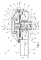
- FIG. 1 shows a sectional view through a pressure control valve, generally designated 10.
- the pressure control valve has a first housing part 12 and a second housing part 14.
- the housing parts 12 and 14 are designed in a manner to be explained as the lower and upper part of the pressure control valve 10.
- the housing part 12 has a tubular extension 16 which forms a connection 18 for a pressure chamber, for example a crankcase of an internal combustion engine, not shown.
- the extension 16 has on its outer circumference 20 a corrugation 22 which is suitable for fastening a flexible connection, for example a hose.
- the housing part 12 also has an opening 24 which is encompassed by an annular collar 26.
- the collar 26 has on its outer circumference a circumferential groove 28 into which a sealing ring 30 can be inserted.
- the collar 26 forms a connection 32 for a connection leading to a vacuum source, not shown, for example an intake manifold of a motor vehicle.
- the housing part 14 is essentially circular and has a circumferential annular groove 36 on its outer edge 34 facing the housing part 12.
- the groove 36 is formed by a shorter leg 38 and a longer leg 40 of the edge 34.
- the housing parts 12 and 14 can, for example, be connected to one another by a latching connection 42 in a manner not to be explained in more detail here.
- the housing part 14 has a sleeve-shaped section 46 which extends coaxially with an axial 44 and which can be closed by means of a cover cap 48.
- the cap 48 has at least a locking lug 50 which can be snapped into a corresponding recess 52 in the sleeve 46.
- the sleeve 46 has an annular collar 54 which forms a circumferential groove 56.
- the housing part 14 also has at least one through opening 58 which connects an interior space 60 with the atmosphere surrounding the pressure control valve 10, that is to say with normal pressure.
- a valve body 62 is located in the interior 60 of the pressure control valve 10.
- the valve body 62 has a sleeve-shaped section 64 which merges into an end section 66.
- the end section 66 has a truncated conical surface 68 which is constricted by a circumferential groove 70.
- the end section 66 also has an axial through opening 72 which opens into an interior 74 of the sleeve-shaped section 64. On the other hand, the through opening 72 opens into an interior 76 of the housing part 14, which can be closed by the cover cap 48.
- the valve body 62 is held by means of a control membrane 78.
- the control membrane 78 has a profiling which, on the one hand, engages in a circumferential groove 80 of the valve body 62 and extends along the sleeve-shaped section 64.
- the control diaphragm 78 is reinforced or stabilized by a diaphragm plate 82, which is formed by a sleeve 84 which surrounds the sleeve-shaped section 64 of the valve body 62.
- An intermediate space 86 located between the sleeve 84 and the sleeve-shaped section 64 of the valve body 62, which is, for example, on a Circular bores arranged through holes can be formed by the sleeve 84 is filled by an axially extending section 88 of the control membrane 78.
- the section 88 of the control membrane 78 is extended beyond the valve body 62 and forms a bead 90 there, which is supported on an inner surface 92 of the housing part 12.
- the control membrane 78 is clamped between the housing parts 12 and 14 in that the control membrane has a circumferential section 94 which comes to rest in the groove 36 of the housing part 14 and is locked by the leg 38.
- the valve body 62 is thus suspended freely by means of the control membrane 78 in the interior 60 of the pressure control valve 10.
- the suspension of the valve body 62 is designed in the idle state of the pressure control valve so that the bead 90 does not touch the inner surface 92, so that there is a direct connection between the connection 32 and the connection 18.
- the bead 90 and the inner surface 92 here form a valve seat 96 to be explained.
- An elastic spring element 100 is supported on a base 98 of the interior 74 of the sleeve-shaped section 64 and is mounted on a counter bearing 102.
- the counter bearing 102 is formed, for example, by cantilever arms 104 projecting into the connection 32.
- the cantilever arms 104 have a central through opening 106.
- the cantilever arms are designed in such a way that the smallest possible cross-sectional constriction occurs for the connection 32.
- the valve body 62 In the unloaded state of the elastic spring element 100, the valve body 62 is in such a position that the Valve seat 96 is open.
- the elastic spring element 100 thus supports the load-bearing action of the control membrane 78 for the valve element 62.
- a spring element (not shown in FIG. 1) can also be provided, which surrounds the sleeve 84.
- An auxiliary diaphragm 110 acts on the valve body 62, which is supported on the one hand in the groove 70 and on the other hand is clamped in the groove 56 of the housing part 14 by means of the cover cap 48.
- An active surface 112 of the auxiliary membrane 110 corresponds to a surface 114 of the valve body 62 which faces the connection 32.
- the arrangement of the valve body 62 divides the interior 60 of the pressure control valve 10 into different areas, of which a first area 116 is acted upon by normal pressure via the passage opening 58.
- This normal pressure is thus - according to the illustration shown in Figure 1 - on the top of the control membrane 78 and the bottom of the auxiliary membrane 110.
- a second area 118 or 119 which is formed by the interior 74 (118) of the valve body 62 and the interior 76 (119), which are connected to one another via the passage opening 72, the negative pressure present at the connection 32 is present.
- a third area 120 has the pressure level applied to the connection 18, which is also applied to the underside of the control membrane 78.
- the pressure control valve 10 shown in FIG. 1 performs the following function: When operating a motor vehicle equipped with the pressure control valve 10, the connection 18 is connected to the crankcase of the internal combustion engine.
- the connection 32 is simultaneously connected to a vacuum source, that is to say, in the case of a motor vehicle, for example to an intake manifold.
- the vacuum source provides a vacuum P U that can fluctuate between values from approx. -100 mbar to -900 mbar. Since the pressure control valve is in its initial position, that is, the valve seat 96 is slightly opened by the force of the spring element 100 or its elastic suspension in the control membrane 78, the negative pressure P U prevailing in the region 114 is via the opened valve seat by means of the negative pressure source 96 transferred to the area 120.
- This vacuum P U thus acts on the crankcase connected to the connection 18, so that it is evacuated and a certain vacuum P K (crankcase pressure) is established there.
- the negative pressure P K in the crankcase should be adjusted to a constant, slight negative pressure of, for example, -10 to -15 mbar.
- the negative pressure P U is simultaneously present on the valve body 62, namely on its surface 114 facing the connection 32. As a result, the valve body 62 is pulled against the force of the spring element 100 in the direction of the connection 32. On the other hand, acts on the valve body 62 via the control membrane 78 on the underside thereof the pressure P K applied to the region 120.
- the force emanating from the vacuum P U must be greater than the sum of the spring element 100 and the forces P K acting on the valve body 62. It is thus clear that to close the valve seat itself, the force exerted on the valve body 62 from the negative pressure P U must be greater than the force of the spring element 100, the force due to the rigidity of the membrane (especially at low temperatures) plus, or at a negative pressure P K minus, the force emanating from the pressure P K.
- a characteristic curve for regulating the pressure P K in the crankcase according to the prior art is shown by way of example in FIG. It is clear that with a fluctuating negative pressure P U, which for example can assume the values down to -900 mbar, the pressure P K ranges from approximately 5 mbar to can fluctuate around -30 mbar. This therefore has a relatively large bandwidth, which opposes the constant, low vacuum of, for example, -15 mbar in the crankcase.
- FIG. 1 The construction of the pressure control valve 10 according to the invention shown in FIG. 1 shows that the vacuum P U present at the connection 32 is simultaneously present in the region 119 formed by the interior space 76 through the through opening 72 of the valve body 62.
- the negative pressure P U acts here on the upper side of the auxiliary membrane 110. Since the auxiliary membrane 110 is firmly anchored with the valve body 62 in its groove 70, a force generated on the upper side of the auxiliary membrane 110 due to the negative pressure P U is transmitted to the valve body 62.
- the force emanating from the vacuum P U is therefore present on the opposite sides of the valve body 62, so that a choice of the size of the opposing surfaces which can be acted upon by the vacuum P U and exert a force on the valve body 62 resulting force is set, which acts on the valve body 62. If the active surface 112 of the auxiliary membrane 110 is now the same size as the surface 114, the valve body 62 is in a force equilibrium with respect to the force originating from the negative pressure P U , that is to say the resulting force has a value of zero.
- a pressure compensator for the valve body 62 is created through the passage opening 72, which connects the regions 116 and 118 to one another.
- the valve body 62 can thus have a position within the pressure control valve 10 occupy, which is independent of a negative pressure P U applied to the connection 32 and thus independent of a force exerted on the valve body 62 from the negative pressure P U.
- the resulting force F can be shifted into the positive or negative range, that is, the valve body 62 is - due to the negative pressure P U - either downwards, as shown in FIG. 1 or pulled up.
- the resulting force ideally has the value zero.
- the force opening or closing the valve seat 96 is determined exclusively by a force of the spring element 100 and a force emanating from the pressure P K in the region 120. It is thus possible to adjust the force emanating from the spring element 100 in such a way that a pressure P K of, for example, -15 mbar acting in the region 120, which is applied to the underside of the control membrane 78, is sufficient to counter the force of the spring element 100 to move so that the valve seat 96 closes. Even a slight increase in the pressure P K in the region 120 above the set value means that the force emanating from the slightly increased pressure P K is added to the force of the spring element 100, so that the valve body 62 is raised and thus the valve seat 96 opens.
- the open valve seat 96 is thus located at the connection 32 applied vacuum P U also in your area 120 so that the crankcase applied to the connection 18 can be evacuated. If this evacuation causes the pressure P K in the region 120 to drop to the preset value of, for example, -15 mbar, this is sufficient to overcome the force of the spring element 100, so that the valve body 62 is moved in the direction of the connection 32 and so that the valve seat 96 closes again.
- a pressure P K is set in the region 120, which fluctuates between the values from approx. -5 to approx. -20 mbar.
- the bandwidth is reduced, that is, the pressure fluctuations in the crankcase approx. 50 %.
- a much more precise setting of a certain, constant, defined pressure P K within the crankcase of, for example, -15 mbar is thus possible.
- the invention is not limited to the illustrated embodiment. in particular, further arrangements are conceivable, which allow the valve body 62 or the valve seat 96 to be designed in such a way that the pressure control valve 10 is regulated independently of the vacuum.
- the control behavior of the pressure control valve 10 can be easily achieved by dimensioning the spring element 100; the stronger this is dimensioned, the slower the valve seat 96 closes, and the active surface 112 of the control membrane 10 and the surface 114 of the valve body 62 are adjusted.
- the vacuum independence can be designed such that there is only an extremely low dependency on the vacuum P U. Fluctuations in the negative pressure P U during the intended use of the pressure control valve 10 can therefore exert little or no influence on the control behavior of the pressure control valve 10, so that overall it is possible to maintain a constant, as low as possible negative pressure P K in the crankcase.
Landscapes
- Engineering & Computer Science (AREA)
- Physics & Mathematics (AREA)
- Mechanical Engineering (AREA)
- General Engineering & Computer Science (AREA)
- Fluid Mechanics (AREA)
- General Physics & Mathematics (AREA)
- Automation & Control Theory (AREA)
- Safety Valves (AREA)
Abstract
Description
Die Erfindung betrifft ein Druckregelventil, insbesondere zum Einstellen eines Unterdrucks in einem Kurbelgehäuse eines Kraftfahrzeuges, nach dem Oberbegriff des Anspruchs 1.The invention relates to a pressure control valve, in particular for setting a negative pressure in a crankcase of a motor vehicle, according to the preamble of claim 1.
Druckregelventile der gattungsgemäßen Art sind bekannt. Diese werden beispielsweise dazu eingesetzt, in einem Kurbelgehäuse eines Kraftfahrzeuges einen Unterdruck einzustellen/einzuregeln. Dieser Unterdruck ist notwendig, da während des bestimmungsgemäßen Gebrauchs des Kurbelgehäuses aufgrund der sich innerhalb eines Zylinderblocks bewegenden Kolben eine Leckage zwischen dem Kolbenring und der Zylinderwand einstellt. Diese Leckage führt zu einem Druckaufbau mit einem Kraftstoff-Luftgemisch innerhalb des Kurbelgehäuses, der abgebaut werden muß. Damit dieser sich aufbauende Druck nicht ins Freie entweichen kann, ist es bekannt, das Kurbelgehäuse mit einem Unterdruck zu beaufschlagen, mittels dem das in das Kurbelgehäuse eintretende Kraftstoff-Luftgemisch abgesaugt und dem Verbrennungsprozeß der Verbrennungskraftmaschine wieder zugeführt werden kann. Die Druckregelventile besitzen hierzu einen mit Unterdruck beaufschlagbaren Anschluß und einen mit dem Kurbelgehäuse als Druckraum verbindbaren Anschluß, wobei ein mittels einer Regelmembran betätigbarer Schließkörper den mit Unterdruck beaufschlagbaren Anschluß und den mit dem Druckraum verbindbaren Anschluß trennt beziehungsweise verbindet. Die Regelmembran ist so ausgelegt, daß diese aufgrund eines sich in dem Kurbelgehäuse aufbauenden Druckes öffnet und hiermit einen mit dem Schließkörper zusammenwirkenden Ventilsitz öffnet, so daß der Unterdruck das Kurbelgehäuse evakuieren kann. Nach Evakuierung des Kurbelgehäuses wird der Schließkörper durch den Unterdruck wieder zum Schließen des Ventilsitzes gezwungen. Der Schließkörper wird hierbei gegen die Kraft eines elastischen Elementes bewegt. Damit bei einem relativ hohen anliegenden Unterdruck an dem Druckregelventil der Unterdruck in dem Kurbelgehäuse begrenzt werden kann, muß das elastische Federelement eine derartige große Federkraft besitzen, daß auch bei geringem Unterdruck im Kurbelgehäuse und hohem anliegenden Unterdruck von der Unterdruckquelle ein sicheres Öffnen des Ventilsitzes gewährleistet ist. Diese relativ große Federkraft behindert jedoch wiederum den Schließvorgang des Druckregelventils, da die Federkraft von dem Unterdruck der Unterdruckquelle überwunden werden muß. Hierbei ist nachteilig, daß aufgrund eines relativ langsamen Schließvorgangs ein sich in dem Kurbelgehäuse einstellender Unterdruck zu groß wird, beziehungsweise der sich in dem Kurbelgehäuse einstellende Unterdruck starken Schwankungen unterliegt.Pressure control valves of the generic type are known. These are used, for example, to set / regulate a negative pressure in a crankcase of a motor vehicle. This negative pressure is necessary because, during the intended use of the crankcase, a leakage occurs between the piston ring and the cylinder wall due to the pistons moving within a cylinder block. This leak leads to a pressure build-up with a fuel-air mixture within the crankcase, which must be reduced. So that this build-up pressure does not go outdoors can escape, it is known to apply a negative pressure to the crankcase, by means of which the fuel-air mixture entering the crankcase can be drawn off and returned to the combustion process of the internal combustion engine. For this purpose, the pressure control valves have a connection which can be acted upon by vacuum and a connection which can be connected to the crankcase as the pressure space, a closing body which can be actuated by means of a control membrane separating or connecting the connection which can be acted upon by vacuum and the connection which can be connected to the pressure space. The control membrane is designed so that it opens due to a pressure building up in the crankcase and thus opens a valve seat interacting with the closing body, so that the vacuum can evacuate the crankcase. After evacuation of the crankcase, the closing body is forced to close the valve seat again by the negative pressure. The closing body is moved against the force of an elastic element. So that the negative pressure in the crankcase can be limited at a relatively high negative pressure applied to the pressure control valve, the elastic spring element must have such a large spring force that even with low negative pressure in the crankcase and high negative pressure applied by the negative pressure source, a secure opening of the valve seat is ensured . However, this relatively large spring force in turn hinders the closing process of the pressure control valve, since the spring force is overcome by the negative pressure of the negative pressure source got to. It is disadvantageous here that, due to a relatively slow closing process, a negative pressure which is established in the crankcase becomes too great, or the negative pressure which is established in the crankcase is subject to strong fluctuations.
Das erfindungsgemäße Druckregelventil mit den im Anspruch 1 genannten Merkmalen bietet demgegenüber den Vorteil, daß unabhängig von der Höhe des an dem mit der Unterdruckquelle verbindbaren Anschlusses anliegenden Unterdruck eine konstante Einstellung eines Unterdrucks in einem Druckraum möglich wird. Dadurch, daß der Regelmembran ein Druckausgleichsglied für den Unterdruck zugeordnet ist, muß zum Betätigen der Regelmembran, und damit zum Öffnen des Ventilsitzes, der anliegende beziehungsweise sich einstellende Druck in dem Druckraum nicht durch eine zusätzliche Federkraft eines elastischen Elementes zum Öffnen des Ventilsitzes beziehungsweise Überwinden des Unterdruckes unterstützt werden. Die Federkraft des elastischen Elementes kann nunmehr auf ein Minimum beschränkt bleiben, so daß der Schließvorgang des Druckregelventils mittels des von der Unterdruckquelle anliegenden Unterdruckes wesentlich schneller vonstatten geht. Durch das schnelle Schließen des Druckregelventils kann in dem Druckraum ein sich einstellender Unterdruck sehr genau auf einen möglichst konstanten Wert eingeregelt werden. Durch dieses präzise und schnelle Ausregeln von sich einstellenden Druckschwankungen in dem Druckraum auf einen bestimmten wählbaren Unterdruckwert mit geringer Schwankung ergibt sich für diesen eine kleine Bandbreite. Durch den Einsatz eines geringer dimensionierten, elastischen Elementes ergibt sich neben dem schnelleren Schließvorgang für das Druckregelventil bei Erreichen des gewählten Unterdruckes im Druckraum ein geringeres Gesamtgewicht.The pressure control valve according to the invention with the features mentioned in claim 1 offers the advantage that a constant setting of a vacuum in a pressure chamber is possible regardless of the level of the vacuum applied to the connection that can be connected to the vacuum source. Because the control diaphragm is assigned a pressure compensating element for the negative pressure, the pressure applied or established in the pressure chamber does not have to be activated by an additional spring force of an elastic element to open the valve seat or overcome the pressure to actuate the control diaphragm and thus to open the valve seat Negative pressure are supported. The spring force of the elastic element can now be kept to a minimum, so that the closing process of the pressure control valve takes place much faster by means of the negative pressure applied by the negative pressure source. By quickly closing the pressure control valve, a negative pressure that is established in the pressure chamber can be adjusted very precisely to a constant value. Thanks to this precise and quick correction of pressure fluctuations in the pressure chamber to a certain selectable negative pressure value with little fluctuation, this results in a small bandwidth. By using a smaller dimensioned elastic element, in addition to the faster closing process for the pressure regulating valve, a lower total weight is achieved in the pressure chamber when the selected negative pressure is reached.
Weitere vorteilhafte Ausgestaltungen der Erfindung ergeben sich aus den in den Unteransprüchen genannten Merkmalen.Further advantageous refinements of the invention result from the features mentioned in the subclaims.
Die Erfindung wird nachfolgend in einem Ausführungsbeispiel anhand der zugehörigen Zeichnungen näher erläutert. Es zeigen:
- Figur 1
- eine Schnittdarstellung durch ein Druckregelventil;
- Figur 2
- eine Kennlinie eines erfindungsgemäßen Druckregelventils und
- Figur 3
- eine Kennlinie eines Druckregelventils nach dem Stand der Technik.
- Figure 1
- a sectional view through a pressure control valve;
- Figure 2
- a characteristic curve of a pressure control valve according to the invention and
- Figure 3
- a characteristic curve of a pressure control valve according to the prior art.
In der Figur 1 ist eine Schnittdarstellung durch ein allgemein mit 10 bezeichnetes Druckregelventil gezeigt. Das Druckregelventil besitzt ein erstes Gehäuseteil 12 und ein zweites Gehäuseteil 14. Die Gehäuseteile 12 und 14 sind in noch zu erläuternder Weise als Unter- beziehungsweise Oberteil des Druckregelventils 10 ausgebildet. Das Gehäuseteil 12 besitzt eine rohrförmige Verlängerung 16, die einen Anschluß 18 für einen Druckraum, beispielsweise ein Kurbelgehäuse einer nicht dargestellten Verbrennungskraftmaschine bildet. Die Verlängerung 16 besitzt auf ihrem Außenumfang 20 eine Riffelung 22, die zum Befestigen einer flexiblen Verbindung, beispielsweise eines Schlauches, geeignet ist. Das Gehäuseteil 12 besitzt weiterhin eine Öffnung 24, die von einem ringförmigen Kragen 26 umgriffen wird. Der Kragen 26 besitzt an seinem Außenumfang eine umlaufende Nut 28, in die ein Dichtungsring 30 einlegbar ist. Der Kragen 26 bildet einen Anschluß 32 für eine zu einer nicht dargestellten Unterdruckquelle, beispielsweise einem Saugrohr eines Kraftfahrzeuges führende Verbindung.FIG. 1 shows a sectional view through a pressure control valve, generally designated 10. The pressure control valve has a
Das Gehäuseteil 14 ist im wesentlichen kreisförmig ausgebildet und besitzt an seinem äußeren, dem Gehäuseteil 12 zugewandtem Rand 34 eine umlaufende Ringnut 36. Die Nut 36 wird hierbei von einem kürzeren Schenkel 38 und einem längeren Schenkel 40 des Randes 34 gebildet. Die Gehäuseteile 12 und 14 sind beispielsweise in hier nicht näher zu erläuternder Weise miteinander durch eine Rastverbindung 42 verbindbar. Das Gehäuseteil 14 weist einen koaxial zu einer Axialen 44 verlaufenden, hülsenförmigen Abschnitt 46 auf, der mittels einer Abdeckkappe 48 verschließbar ist. Die Abdeckkappe 48 besitzt wenigstens eine Rastnase 50, die in eine entsprechende Ausnehmung 52 der Hülse 46 einrastbar ist. Die Hülse 46 besitzt einen ringförmigen Kragen 54, der eine umlaufende Nut 56 ausbildet. Das Gehäuseteil 14 besitzt ferner wenigstens eine Durchgangsöffnung 58, die einen Innenraum 60 mit der das Druckregelventil 10 umgebenden Atmosphäre, also mit Normaldruck, verbindet.The
In dem Innenraum 60 des Druckregelventils 10 befindet sich ein Ventilkörper 62. Der Ventilkörper 62 besitzt einen hülsenförmigen Abschnitt 64, der in einen Endabschnitt 66 übergeht. Der Endabschnitt 66 besitzt eine kegelstumpfförmige Mantelfläche 68, die von einer umlaufenden Nut 70 eingeschnürt wird. Der Endabschnitt 66 besitzt ferner eine axiale Durchgangsöffnung 72, die in einem Innenraum 74 des hülsenförmigen Abschnitts 64 mündet. Andererseits mündet die Durchgangsöffnung 72 in einem Innenraum 76 des Gehäuseteils 14, der durch die Abdeckkappe 48 verschließbar ist. Der Ventilkörper 62 wird mittels einer Regelmembran 78 gehalten. Die Regelmembran 78 besitzt eine Profililierung, die einerseits in eine umlaufende Nut 80 des Ventilkörpers 62 eingreift und sich entlang des hülsenförmigen Abschnitts 64 erstreckt. Die Regelmembran 78 ist durch einen Membranteller 82 verstärkt beziehungsweise stabilisiert, der von einer Hülse 84 gebildet wird, die den hülsenförmigen Abschnitt 64 des Ventilkörpers 62 umgreift. Ein zwischen der Hülse 84 und dem hülsenförmigen Abschnitt 64 des Ventilkörpers 62 sich befindender Zwischenraum 86, der beispielsweise von auf einer Kreislinle angeordneten Durchgangsbohrungen durch die Hülse 84 gebildet werden kann, wird von einem axial verlaufenden Abschnitt 88 der Regelmembran 78 ausgefüllt. Der Abschnitt 88 der Regelmembran 78 ist über den Ventilkörper 62 hinaus verlängert und bildet dort einen Wulst 90 aus, der sich an einer Innenfläche 92 des Gehäuseteils 12 abstützt. Andererseits ist die Regelmembran 78 zwischen den Gehäuseteilen 12 und 14 eingeklemmt, indem die Regelmembran einen umlaufenden Abschnitt 94 aufweist, der in der Nut 36 des Gehäuseteils 14 zu liegen kommt und durch den Schenkel 38 arretiert ist. Der Ventilkörper 62 ist somit mittels der Regelmembran 78 in dem Innenraum 60 des Druckregelventils 10 frei aufgehängt. Die Aufhängung des Ventilkörpers 62 ist im Ruhezustand des Druckregelventils so ausgelegt, daß der Wulst 90 die Innenfläche 92 nicht berührt, so daß eine direkte Verbindung zwischen dem Anschluß 32 und dem Anschluß 18 besteht. Der Wulst 90 und die Innenfläche 92 bilden hierbei einen noch zu erläuternden Ventilsitz 96 aus.A
An einem Grund 98 des Innenraums 74 des hülsenförmigen Abschnitts 64 stützt sich ein elastisches Federelement 100 ab, das an einem Gegenlager 102 gegengelagert ist. Das Gegenlager 102 wird beispielsweise von in den Anschluß 32 hineinragenden Kragarmen 104 gebildet. Die Kragarme 104 besitzen eine zentrale Durchgangsöffnung 106. Die Kragarme sind so gestaltet, daß eine möglichst geringe Querschnittsverengung für den Anschluß 32 eintritt. In unbelastetem Zustand des elastischen Federelementes 100 befindet sich der Ventilkörper 62 in einer solchen Position, daß der Ventilsitz 96 geöffnet ist. Das elastische Federelement 100 unterstützt somit die Tragwirkung der Regelmembran 78 für das Ventilelement 62. Anstelle des Federelementes 100 kann auch ein - in der Figur 1 nicht dargesteltes - Federelement vorgesehen sein, das die Hülse 84 umgreift.An
An den Ventilkörper 62 greift eine Hilfsmembran 110 an, die sich einerseits in der Nut 70 abstützt und andererseits mittels der Abdeckkappe 48 in der Nut 56 des Gehäuseteils 14 festgeklemmt ist. Eine Wirkfläche 112 der Hilfsmembran 110 entspricht einer Fläche 114 des Ventilkörpers 62, die dem Anschluß 32 zugewandt ist.An
Durch die Anordnung des Ventilkörpers 62 wird der Innenraum 60 des Druckregelventils 10 in verschiedene Bereiche aufgeteilt, von denen ein erster Bereich 116 mit Normaldruck über die Durchgangsöffnung 58 beaufschlagt ist. Dieser Normaldruck liegt somit - gemäß der in Figur 1 gezeigten Darstellung - an der Oberseite der Regelmembran 78 und der Unterseite der Hilfsmembran 110 an. In einem zweiten Bereich 118 beziehungsweise 119, der von dem Innenraum 74 (118) des Ventilkörpers 62 und dem Innenraum 76 (119) gebildet wird, die über die Durchgangsöffnung 72 miteinander in Verbindung stehen, liegt der an dem Anschluß 32 anliegende Unterdruck an. Ein dritter Bereich 120 weist das an dem Anschluß 18 anliegende Druckniveau auf, das gleichzeitig an der Unterseite der Regelmembran 78 anliegt.The arrangement of the
Das in Figur 1 gezeigte Druckregelventil 10 übt folgende Funktion aus:
Beim Betrieb eines mit dem Druckregelventil 10 ausgestatteten Kraftfahrzeuges ist der Anschluß 18 mit dem Kurbelgehäuse der Verbrennungskraftmaschine verbunden. Der Anschluß 32 ist gleichzeitig mit einer Unterdruckquelle, das heißt, bei einem Kraftfahrzeug beispielsweise mit einem Saugrohr, verbunden. Die Unterdruckquelle stellt einen Unterdruck PU zur Verfügung, der zwischen Werten von ca. -100 mbar bis -900 mbar schwanken kann. Da sich das Druckregelventil in seiner Ausgangsstellung befindet, das heißt, der Ventilsitz 96 ist durch die Kraft des Federelementes 100 beziehungsweise dessen elastischer Aufhängung in der Regelmembran 78 leicht geöffnet, wird mittels der Unterdruckquelle der in dem Bereich 114 herrschende Unterdruck PU über den geöffneten Ventilsitz 96 auf den Bereich 120 übertragen. Dieser Unterdruck PU wirkt somit auf das an den Anschluß 18 angeschlossene Kurbelgehäuse, so daß dieses evakuiert wird und sich dort ein bestimmter Unterdruck PK (Kurbelgehäusedruck) einstellt. Der Unterdruck PK in dem Kurbelgehäuse soll auf einen möglichst konstanten, geringfügigen Unterdruck von zum Beispiel -10 bis -15 mbar eingeregelt werden. Der Unterdruck PU liegt gleichzeitig an dem Ventilkörper 62 und zwar an dessen dem Anschluß 32 zugewandten Fläche 114 an. Hierdurch wird der Ventilkörper 62 gegen die Kraft des Federelementes 100 in Richtung des Anschlusses 32 gezogen. Andererseits wirkt an dem Ventilkörper 62 über die Regelmembran 78 der an dessen Unterseite in dem Bereich 120 anliegende Druck PK. Soll nunmehr der Ventilkörper 62 in Richtung des Anschlusses 32 bewegt werden, so daß der von dem Wulst 90 und der Innenfläche 92 gebildete Ventilsitz 96 schließt, so muß die von dem Unterdruck PU ausgehende Kraft größer sein als die Summe der von dem Federelement 100 und dem Druck PK auf den Ventilkörper 62 wirkenden Kräfte. Somit wird klar, daß zum Schließen des Ventilsitzes an sich die von dem Unterdruck PU ausgehende Kraft auf den Ventilkörper 62 größer sein muß als die Kraft des Federelementes 100, der Kraft aufgrund der Steifigkeit der Membran (besonders bei tiefen Temperaturen) plus, beziehungsweise bei einem Unterdruck PK minus, die von dem Druck PK ausgehende Kraft.The
When operating a motor vehicle equipped with the
Beim Stand der Technik, das heißt, ohne Anordnung der Hilfsmembran 10 und deren noch zu erläuternder Wirkungsweise, mußte auch für den Fall ein sicheres Öffnen des Ventilsitzes 96 gewährleistet sein, daß der an dem Anschluß 32 anliegende Unterdruck PU seinen Maximalwert von beispielsweise -900 mbar aufweist, so daß bei einem angenommenen Querschnitt der Fläche 114, die mit dem Unterdruck PU beaufschlagt wird, mit einem Durchmesser von ca. 10 mm eine Öffnungskraft F von ca. 6 N aufgebracht werden mußte, um den gewünschten Unterdruck PK im Kurbelgehäuse von ca. -15 mbar einregeln zu können, das heißt, beim Erreichen eines höheren Wertes in dem Kurbelgehäuse, beispielsweise durch die bereits erwähnte Leckage, mußte der Ventilsitz 96 öffnen. Dies war nur durch ein relativ starkes Federelement 100 möglich, das der von dem Unterdruck PU ausgehenden Kraft eine entsprechend große Gegenkraft entgegensetzt. Bei offenem Ventilsitz 96 konnte dann durch den Unterdruck PU das Kurbelgehäuse über den Anschluß 18 evakuiert werden, so daß sich dort ein Druckabbau ergibt. Dieser Druckabbau soll, wie bereits erwähnt, auf einen möglichst konstanten, geringfügigen Unterdruck von beispielsweise -15 mbar begrenzt werden. Hierzu ist ein rechtzeitiges Schließen des Ventilsitzes 96 notwendig. Da jedoch nun das Federelement gemäß der Erläuterung eine möglichst große Federkraft aufweisen muß, ist ein Schließen des Ventilsitzes beim Stand der Technik nur relativ langsam möglich, da die relativ große Kraft des Federelementes 100 erst durch die von dem Unterdruck PU ausgehende, auf den Ventilkörper 62 wirkende Kraft überwunden werden muß. Aufgrund dieses langsamen Schließens des Ventilsitzes 96 erfolgt eine Evakuierung des an dem Anschluß 18 angeschlossenen Kurbelgehäuses für einen längeren Zeitraum als eigentlich zur Einstellung des gewünschten Unterdruckes von -15 mbar notwendig wäre, so daß sich dort ein entsprechend höherer Unterdruck PK einstellt. Durch die Regelfunktion des Druckregelventils 10, die quasi eine Zweipunktregelung darstellt, ergab sich eine relativ große Bandbreite der Schwankungen des Druckes PK in dem Kurbelgehäuse.In the prior art, that is, without arranging the
Anhand der Figur 3 ist eine Kennlinie für die Regelung des Druckes PK in dem Kurbelgehäuse gemäß dem Stand der Technik beispielhaft dargestellt. Es wird deutlich, daß bei einem schwankenden Unterdruck PU, der beispielsweise die Werte bis -900 mbar annehmen kann, der Druck PK in Bereichen von ca. 5 mbar bis ca. -30 mbar schwanken kann. Dieser besitzt somit eine relativ große Bandbreite, die dem möglichst konstanten, geringen Unterdruck von beispielsweise -15 mbar im Kurbelgehäuse entgegensteht.A characteristic curve for regulating the pressure P K in the crankcase according to the prior art is shown by way of example in FIG. It is clear that with a fluctuating negative pressure P U, which for example can assume the values down to -900 mbar, the pressure P K ranges from approximately 5 mbar to can fluctuate around -30 mbar. This therefore has a relatively large bandwidth, which opposes the constant, low vacuum of, for example, -15 mbar in the crankcase.
Durch den in Figur 1 gezeigten erfindungsgemäßen Aufbau des Druckregelventils 10 ergibt sich, daß der an dem Anschluß 32 anliegende Unterdruck PU über die Durchgangsöffnung 72 des Ventilkörpers 62 gleichzeitig in dem von dem Innenraum 76 gebildeten Bereich 119 anliegt. Der Unterdruck PU wirkt hier auf die Oberseite der Hilfsmembran 110. Da die Hilfsmembran 110 mit dem Ventilkörper 62 in dessen Nut 70 fest verankert ist, wird eine aufgrund des Unterdruckes PU an der Oberseite der Hilfsmembran 110 erzeugte Kraft auf den Ventilkörper 62 übertragen. Die von dem Unterdruck PU ausgehende Kraft liegt somit an den sich gegenüberliegenden Seiten des Ventilkörpers 62 an, so daß durch eine Wahl der Größe der sich gegenüberliegenden Flächen, die mit dem Unterdruck PU beaufschlagbar sind und eine Kraft auf den Ventilkörper 62 ausüben, eine resultierende Kraft eingestellt wird, die auf den Ventilkörper 62 wirkt. Ist nunmehr die Wirkfläche 112 der Hilfsmembran 110 gleich groß wie die Fläche 114, befindet sich der Ventilkörper 62, bezogen auf die von dem Unterdruck PU ausgehende Kraft in einem Kräftegleichgewicht, das heißt, die resultierende Kraft hat einen Wert von Null. Durch die Durchgangsöffnung 72, die die Bereiche 116 und 118 miteinander verbindet, wird eine Druckwaage für den Ventilkörper 62 geschaffen. Der Ventilkörper 62 kann somit eine Position innerhalb des Druckregelventil 10 einnehmen, die unabhängig von einem an dem Anschluß 32 anliegenden Unterdruck PU und damit unabhängig von einer von dem Unterdruck PU ausgehenden, auf den Ventilkörper 62 wirkenden Kraft ist. Durch eine Variation der Größenverhältnisse der Wirkfläche 112 zu der Fläche 114 kann die resultierende Kraft F in den positiven beziehungsweise negativen Bereich verschoben werden, das heißt, der Ventilkörper 62 wird aufgrund des Unterdruckes PU - gemäß der in Figur 1 gezeigten Darstellung - entweder nach unten oder nach oben gezogen. Zur Wahrung der Unabhängigkeit von dem Unterdruck PU besitzt die resultierende Kraft idealerweise jedoch den Wert Null.The construction of the
Aufgrund dieser Zusammenhänge wird die den Ventilsitz 96 öffnende beziehungsweise schließende Kraft ausschließlich von einer Kraft des Federelementes 100 und einer von dem Druck PK in dem Bereich 120 ausgehenden Kraft bestimmt. Somit ist es möglich, die von dem Federelement 100 ausgehende Kraft so einzustellen, daß ein in dem Bereich 120 wirkender Druck PK von beispielsweise -15 mbar ausreicht, der an der Unterseite der Regelmembran 78 anliegt, den Ventilkörper 62 entgegen der Kraft des Federelementes 100 zu bewegen, so daß der Ventilsitz 96 schließt. Schon ein geringfügiges Ansteigen des Druckes PK in dem Bereich 120 über den eingestellten Wert führt dazu, daß sich die von dem leicht erhöhten Druck PK ausgehende Kraft mit der Kraft des Federelementes 100 addiert, so daß der Ventilkörper 62 angehoben wird und damit der Ventilsitz 96 öffnet. Über den offenen Ventilsitz 96 liegt somit der an dem Anschluß 32 anliegende Unterdruck PU ebenfalls in dein Bereich 120 an, so daß das an dem Anschluß 18 anliegende Kurbelgehäuse evakuiert werden kann. Sinkt durch diese Evakuierung der in dem Bereich 120 anliegende Druck PK auf den voreingestellten Wert von beispielsweise -15 mbar ab, reicht dies aus, um die Kraft des Federelementes 100 zu überwinden, so daß der Ventilkörper 62 in Richtung des Anschlusses 32 bewegt wird und damit der Ventilsitz 96 wieder schließt.On the basis of these relationships, the force opening or closing the
Dadurch, daß das Federelement 100 keinen großen Kraftbeitrag zum Öffnen des Ventilsitzes 96 mehr leisten muß, kann dieses entsprechend schwächer dimensioniert werden. Hierdurch ergibt der Vorteil, daß der Ventilsitz 96 sehr viel schneller schließt, da nunmehr ein geringfügiger Druckabfall in dem Bereich 120 ausreicht, die Kraft des Federelementes 100 zu überwinden, so daß der Ventilkörper 62 den Ventilsitz 96 schließt. Die Schwankungen des Druckes PK in dem Bereich 120 und damit in dem an dem Anschluß 18 angeschlossenen Kurbelgehäuse, können damit in einem eng begrenzten Bereich eingestellt werden. Anhand der in Figur 2 dargestellten Kennlinie wird das Regelverhalten des Druckregelventils 10 in der in Figur 1 gezeigten Ausführung verdeutlicht. Bei einem angenommenen Unterdruck PU, der wiederum Werte bis -900 mbar annehmen kann, wird in dem Bereich 120 ein Druck PK, der zwischen den Werten von ca. -5 bis ca. -20 mbar schwankt, eingestellt. Gegenüber den in Figur 3 gezeigten, bereits erläuterten Kennlinien, ergibt sich somit eine Verkleinerung der Bandbreite, das heißt der Druckschwankungen in dem Kurbelgehäuse, auf ca. 50 %. Somit ist ein sehr viel genaueres Einstellen eines bestimmten, konstanten, definierten Druckes PK innerhalb des Kurbelgehäuses von beispielsweise -15 mbar möglich.Because the
Die Erfindung beschränkt sich nicht auf das dargestellte Ausführungsbeispiel. insbesondere sind weitere Anordnungen denkbar, die es gestatten, den Ventilkörper 62 beziehungsweise den Ventilsitz 96 so aus zugestalten, daß eine Unterdruck unabhängige Regelung des Druckregelventils 10 erfolgt. Das Regelverhalten des Druckregelventils 10 kann in einfacher Weise durch eine Dimensionierung des Federelementes 100; je stärker dieses dimensioniert ist, umso langsamer schließt der Ventilsitz 96, und eine Abstimmung der Wirkfläche 112 der Regelmembran 10 und der Fläche 114 des Ventilkörpers 62 eingestellt werden. So kann beispielsweise die Unterdruckunabhängigkeit dahingehend ausgelegt werden, daß nur eine äußerst geringe Abhängigkeit von dem Unterdruck PU besteht. Schwankungen des Unterdruckes PU während des bestimmungsgemäßen Einsatzes des Druckregelventils 10 können somit keinen beziehungsweise nur einen äußerst geringen Einfluß auf das Regelverhalten des Druckregelventils 10 ausüben, so daß insgesamt die Einhaltung eines konstanten, möglichst geringfügigen Unterdruckes PK in dem Kurbelgehäuse möglich wird.The invention is not limited to the illustrated embodiment. in particular, further arrangements are conceivable, which allow the
Claims (11)
Applications Claiming Priority (2)
| Application Number | Priority Date | Filing Date | Title |
|---|---|---|---|
| DE19501447 | 1995-01-19 | ||
| DE1995101447 DE19501447A1 (en) | 1995-01-19 | 1995-01-19 | Pressure control valve |
Publications (2)
| Publication Number | Publication Date |
|---|---|
| EP0724206A2 true EP0724206A2 (en) | 1996-07-31 |
| EP0724206A3 EP0724206A3 (en) | 1997-08-20 |
Family
ID=7751807
Family Applications (1)
| Application Number | Title | Priority Date | Filing Date |
|---|---|---|---|
| EP95115299A Withdrawn EP0724206A3 (en) | 1995-01-19 | 1995-09-28 | Pressure regulating valve |
Country Status (2)
| Country | Link |
|---|---|
| EP (1) | EP0724206A3 (en) |
| DE (1) | DE19501447A1 (en) |
Cited By (4)
| Publication number | Priority date | Publication date | Assignee | Title |
|---|---|---|---|---|
| WO2002073009A1 (en) * | 2001-03-13 | 2002-09-19 | Volvo Lastvagnar Ab | Valve device for pressure control in a combustion engine, and a method for such pressure control |
| FR2826691A1 (en) | 2001-07-02 | 2003-01-03 | Solvay | CIRCUIT FOR RESPIRATING THE CRANKCASE GASES OF AN INTERNAL COMBUSTION ENGINE |
| DE202008008035U1 (en) | 2008-06-16 | 2008-09-18 | Reinz-Dichtungs-Gmbh | Adaptive suction vacuum compensating pressure control valve with variable switching point |
| DE102008028543B3 (en) * | 2008-06-16 | 2009-10-08 | Reinz-Dichtungs-Gmbh | Valve for use in venting system for ventilation of crank case of combustion engine, has auxiliary membrane and bar provided for producing force on flexibly movable tax control membrane as function of difference of pressure |
Families Citing this family (7)
| Publication number | Priority date | Publication date | Assignee | Title |
|---|---|---|---|---|
| DE10061306A1 (en) * | 2000-12-08 | 2002-07-11 | Mann & Hummel Filter | Pressure control valve with a pressurized membrane |
| DE20115847U1 (en) | 2001-09-26 | 2001-12-13 | Loctite Deutschland GmbH, 81925 München | Device for valve actuation and for setting the valve lift |
| DE10249720A1 (en) | 2002-10-25 | 2004-05-06 | Robert Bosch Gmbh | Pressure control valve |
| DE10337689B4 (en) * | 2003-08-16 | 2005-10-13 | Dieter Schulz | Constant pressure valve, method for shutting off a volume flow through such a constant pressure valve and use of a constant pressure valve |
| DE102008030134A1 (en) | 2007-08-07 | 2009-02-19 | Dichtungstechnik G. Bruss Gmbh & Co. Kg | Pressure regulating valve for use in cylinder head cover of internal combustion engine of motor vehicle, has valve element arranged in compensation chamber such that element is pressure compensated with respect to pressure in flow chamber |
| DE102013019885B4 (en) * | 2013-11-28 | 2021-02-04 | Mann+Hummel Gmbh | Pressure control valve |
| DE102020208393B3 (en) | 2020-07-03 | 2021-11-04 | Mtu Friedrichshafen Gmbh | Pressure regulating device for regulating the crankcase pressure of an internal combustion engine and internal combustion engine with such a pressure regulating device |
Family Cites Families (6)
| Publication number | Priority date | Publication date | Assignee | Title |
|---|---|---|---|---|
| GB662741A (en) * | 1948-10-06 | 1951-12-12 | Evered & Co Ltd | Improvements relating to fluid pressure governors |
| US3263660A (en) * | 1964-06-17 | 1966-08-02 | Gen Motors Corp | Pressure regulator |
| US3262436A (en) * | 1964-12-08 | 1966-07-26 | Gen Motors Corp | Pressure regulating device |
| GB2078341A (en) * | 1980-06-18 | 1982-01-06 | Crosweller & Co Ltd W | A gas pressure governor |
| DE3611869A1 (en) * | 1986-04-09 | 1987-10-22 | Ruhrgas Ag | Regulator, in particular for gas engines |
| DE4022129A1 (en) * | 1990-07-11 | 1992-01-16 | Mann & Hummel Filter | PRESSURE CONTROL VALVE FOR INSTALLATION IN A BLEEDING LINE ON AN INTERNAL COMBUSTION ENGINE |
-
1995
- 1995-01-19 DE DE1995101447 patent/DE19501447A1/en not_active Withdrawn
- 1995-09-28 EP EP95115299A patent/EP0724206A3/en not_active Withdrawn
Non-Patent Citations (1)
| Title |
|---|
| None |
Cited By (6)
| Publication number | Priority date | Publication date | Assignee | Title |
|---|---|---|---|---|
| WO2002073009A1 (en) * | 2001-03-13 | 2002-09-19 | Volvo Lastvagnar Ab | Valve device for pressure control in a combustion engine, and a method for such pressure control |
| US6802303B2 (en) | 2001-03-13 | 2004-10-12 | Volvo Lastvagnar Ab | Valve device for pressure control in a combustion engine, and a method for such pressure control |
| FR2826691A1 (en) | 2001-07-02 | 2003-01-03 | Solvay | CIRCUIT FOR RESPIRATING THE CRANKCASE GASES OF AN INTERNAL COMBUSTION ENGINE |
| DE202008008035U1 (en) | 2008-06-16 | 2008-09-18 | Reinz-Dichtungs-Gmbh | Adaptive suction vacuum compensating pressure control valve with variable switching point |
| DE102008028543B3 (en) * | 2008-06-16 | 2009-10-08 | Reinz-Dichtungs-Gmbh | Valve for use in venting system for ventilation of crank case of combustion engine, has auxiliary membrane and bar provided for producing force on flexibly movable tax control membrane as function of difference of pressure |
| US8297264B2 (en) | 2008-06-16 | 2012-10-30 | Reinz-Dichtungs-Gmbh | Adaptive pressure control valve with variable switching point |
Also Published As
| Publication number | Publication date |
|---|---|
| DE19501447A1 (en) | 1996-07-25 |
| EP0724206A3 (en) | 1997-08-20 |
Similar Documents
| Publication | Publication Date | Title |
|---|---|---|
| EP0845077B1 (en) | Fuel injection device for internal combustion engines | |
| EP0471142A2 (en) | Pressure regulating valve for the installation in a vent conduit of a combustion engine | |
| EP1772618A1 (en) | Common rail injector | |
| EP1913241A1 (en) | Pneumatic pressure control valve | |
| EP1828593A1 (en) | Fuel injection valve for an internal combustion engine | |
| EP0325958A1 (en) | Hydraulically actuated valve | |
| EP1020936B1 (en) | Control element with a controllable length actuator | |
| EP0724206A2 (en) | Pressure regulating valve | |
| EP1321661B1 (en) | Fuel injection valve for internal combustion engines | |
| DE2830738C3 (en) | Pneumatically operated adjustment device | |
| DE69900474T2 (en) | FUEL PULSATION DAMPER WITH VACUUM-CONTROLLED PRELOAD | |
| EP0802470B1 (en) | Pressure regulating valve | |
| DE20016214U1 (en) | Throttle valve for automatic regulation of the pressure in the crankcase of an internal combustion engine | |
| DE102018207287A1 (en) | Valve arrangement for gas pressure regulation, fuel system with valve arrangement for gas pressure regulation | |
| DE2348865A1 (en) | Fuel injector system for compression ignition engines - has pressure relief valve fitted inside pump delivery valve to relieve pressure oscillations | |
| DE102005015735A1 (en) | Fuel injector | |
| EP1518049A1 (en) | Fuel injection valve for an internal combustion engine | |
| DE19954288A1 (en) | Fuel injection valve for fitting to internal combustion engines has an injection valve element to control injection openings, a control valve to affect movement in injection valve elements and a valve element for regulating pressure | |
| EP1402174B1 (en) | Fuel injection device for an internal combustion engine | |
| DE19654782C1 (en) | Injector for diesel engine | |
| DE19912249C2 (en) | Valve for a milk line | |
| DE2712511A1 (en) | Diaphragm valve for exhaust gas feed back - has housing edge with raised part working with corresponding recessed diaphragm part to prevent tearing | |
| EP0198166B1 (en) | Diaphragm-actuated pneumatic correcting device for a fuel injection pump of an internal-combustion engine | |
| DE10236783B4 (en) | Pressure control valve | |
| DE10050599B4 (en) | Injection valve with a pump piston |
Legal Events
| Date | Code | Title | Description |
|---|---|---|---|
| PUAI | Public reference made under article 153(3) epc to a published international application that has entered the european phase |
Free format text: ORIGINAL CODE: 0009012 |
|
| AK | Designated contracting states |
Kind code of ref document: A2 Designated state(s): DE FR GB IT |
|
| PUAL | Search report despatched |
Free format text: ORIGINAL CODE: 0009013 |
|
| AK | Designated contracting states |
Kind code of ref document: A3 Designated state(s): DE FR GB IT |
|
| STAA | Information on the status of an ep patent application or granted ep patent |
Free format text: STATUS: THE APPLICATION IS DEEMED TO BE WITHDRAWN |
|
| 18D | Application deemed to be withdrawn |
Effective date: 19980331 |