EP0724147A2 - Verfahren und Vorrichtung zur Messung der optischen Anisotropie - Google Patents
Verfahren und Vorrichtung zur Messung der optischen Anisotropie Download PDFInfo
- Publication number
- EP0724147A2 EP0724147A2 EP96300507A EP96300507A EP0724147A2 EP 0724147 A2 EP0724147 A2 EP 0724147A2 EP 96300507 A EP96300507 A EP 96300507A EP 96300507 A EP96300507 A EP 96300507A EP 0724147 A2 EP0724147 A2 EP 0724147A2
- Authority
- EP
- European Patent Office
- Prior art keywords
- transparent member
- optical system
- examined
- region
- liquid crystal
- Prior art date
- Legal status (The legal status is an assumption and is not a legal conclusion. Google has not performed a legal analysis and makes no representation as to the accuracy of the status listed.)
- Withdrawn
Links
- 230000003287 optical effect Effects 0.000 title claims abstract description 171
- 238000000034 method Methods 0.000 title claims description 13
- 239000004973 liquid crystal related substance Substances 0.000 claims abstract description 138
- 239000007788 liquid Substances 0.000 claims abstract description 25
- 239000011521 glass Substances 0.000 claims description 115
- 238000005259 measurement Methods 0.000 claims description 101
- 239000000758 substrate Substances 0.000 claims description 22
- 238000000691 measurement method Methods 0.000 claims description 9
- 230000008569 process Effects 0.000 claims description 4
- 238000012544 monitoring process Methods 0.000 claims 4
- 230000003993 interaction Effects 0.000 abstract description 2
- 210000002858 crystal cell Anatomy 0.000 description 52
- 230000004907 flux Effects 0.000 description 36
- 238000004519 manufacturing process Methods 0.000 description 14
- 230000010287 polarization Effects 0.000 description 10
- 230000006866 deterioration Effects 0.000 description 4
- 239000000463 material Substances 0.000 description 4
- 239000000126 substance Substances 0.000 description 4
- 230000004075 alteration Effects 0.000 description 3
- 210000004027 cell Anatomy 0.000 description 3
- 230000008859 change Effects 0.000 description 3
- 230000006872 improvement Effects 0.000 description 3
- 230000007480 spreading Effects 0.000 description 3
- 238000003892 spreading Methods 0.000 description 3
- 239000013078 crystal Substances 0.000 description 2
- 238000011161 development Methods 0.000 description 2
- NZZFYRREKKOMAT-UHFFFAOYSA-N diiodomethane Chemical compound ICI NZZFYRREKKOMAT-UHFFFAOYSA-N 0.000 description 2
- 238000009826 distribution Methods 0.000 description 2
- 230000005684 electric field Effects 0.000 description 2
- 239000005308 flint glass Substances 0.000 description 2
- 230000007246 mechanism Effects 0.000 description 2
- 229920001721 polyimide Polymers 0.000 description 2
- 239000012780 transparent material Substances 0.000 description 2
- BWGNESOTFCXPMA-UHFFFAOYSA-N Dihydrogen disulfide Chemical compound SS BWGNESOTFCXPMA-UHFFFAOYSA-N 0.000 description 1
- 235000010627 Phaseolus vulgaris Nutrition 0.000 description 1
- 244000046052 Phaseolus vulgaris Species 0.000 description 1
- JMBNQWNFNACVCB-UHFFFAOYSA-N arsenic tribromide Chemical compound Br[As](Br)Br JMBNQWNFNACVCB-UHFFFAOYSA-N 0.000 description 1
- 229940077468 arsenic tribromide Drugs 0.000 description 1
- 201000009310 astigmatism Diseases 0.000 description 1
- 230000008901 benefit Effects 0.000 description 1
- 230000005540 biological transmission Effects 0.000 description 1
- 238000000748 compression moulding Methods 0.000 description 1
- 238000012790 confirmation Methods 0.000 description 1
- 238000001514 detection method Methods 0.000 description 1
- 230000000694 effects Effects 0.000 description 1
- 238000011156 evaluation Methods 0.000 description 1
- 239000004744 fabric Substances 0.000 description 1
- 239000000835 fiber Substances 0.000 description 1
- 230000006870 function Effects 0.000 description 1
- AMGQUBHHOARCQH-UHFFFAOYSA-N indium;oxotin Chemical compound [In].[Sn]=O AMGQUBHHOARCQH-UHFFFAOYSA-N 0.000 description 1
- 238000000059 patterning Methods 0.000 description 1
- 230000002093 peripheral effect Effects 0.000 description 1
- 239000004033 plastic Substances 0.000 description 1
- 230000005855 radiation Effects 0.000 description 1
- 239000000565 sealant Substances 0.000 description 1
- 239000004065 semiconductor Substances 0.000 description 1
- 230000035945 sensitivity Effects 0.000 description 1
- 238000000638 solvent extraction Methods 0.000 description 1
- 230000004304 visual acuity Effects 0.000 description 1
Images


Classifications
-
- G—PHYSICS
- G01—MEASURING; TESTING
- G01N—INVESTIGATING OR ANALYSING MATERIALS BY DETERMINING THEIR CHEMICAL OR PHYSICAL PROPERTIES
- G01N21/00—Investigating or analysing materials by the use of optical means, i.e. using sub-millimetre waves, infrared, visible or ultraviolet light
- G01N21/17—Systems in which incident light is modified in accordance with the properties of the material investigated
- G01N21/21—Polarisation-affecting properties
-
- G—PHYSICS
- G02—OPTICS
- G02F—OPTICAL DEVICES OR ARRANGEMENTS FOR THE CONTROL OF LIGHT BY MODIFICATION OF THE OPTICAL PROPERTIES OF THE MEDIA OF THE ELEMENTS INVOLVED THEREIN; NON-LINEAR OPTICS; FREQUENCY-CHANGING OF LIGHT; OPTICAL LOGIC ELEMENTS; OPTICAL ANALOGUE/DIGITAL CONVERTERS
- G02F1/00—Devices or arrangements for the control of the intensity, colour, phase, polarisation or direction of light arriving from an independent light source, e.g. switching, gating or modulating; Non-linear optics
- G02F1/01—Devices or arrangements for the control of the intensity, colour, phase, polarisation or direction of light arriving from an independent light source, e.g. switching, gating or modulating; Non-linear optics for the control of the intensity, phase, polarisation or colour
- G02F1/13—Devices or arrangements for the control of the intensity, colour, phase, polarisation or direction of light arriving from an independent light source, e.g. switching, gating or modulating; Non-linear optics for the control of the intensity, phase, polarisation or colour based on liquid crystals, e.g. single liquid crystal display cells
-
- G—PHYSICS
- G01—MEASURING; TESTING
- G01N—INVESTIGATING OR ANALYSING MATERIALS BY DETERMINING THEIR CHEMICAL OR PHYSICAL PROPERTIES
- G01N21/00—Investigating or analysing materials by the use of optical means, i.e. using sub-millimetre waves, infrared, visible or ultraviolet light
- G01N21/17—Systems in which incident light is modified in accordance with the properties of the material investigated
- G01N21/21—Polarisation-affecting properties
- G01N21/211—Ellipsometry
- G01N2021/212—Arrangement with total internal reflection
-
- G—PHYSICS
- G01—MEASURING; TESTING
- G01N—INVESTIGATING OR ANALYSING MATERIALS BY DETERMINING THEIR CHEMICAL OR PHYSICAL PROPERTIES
- G01N21/00—Investigating or analysing materials by the use of optical means, i.e. using sub-millimetre waves, infrared, visible or ultraviolet light
- G01N21/17—Systems in which incident light is modified in accordance with the properties of the material investigated
- G01N21/21—Polarisation-affecting properties
- G01N2021/218—Measuring properties of electrooptical or magnetooptical media
Definitions
- the present invention relates to an apparatus and a method for measuring the optical anisotropy of a substance. More particularly, the present invention relates to an apparatus and a method for measuring an optical anisotropy of a liquid crystal in order to determine a pretilt angle of the liquid crystal, and a process for producing a liquid crystal device by using the optical anisotropy measurement apparatus.
- a treatment for aligning liquid crystal molecules such as rubbing has been generally performed.
- the aligning treatment liquid crystal molecules are aligned to form a certain angle (called a pretilt angle), with respect to a substrate surface in a liquid crystal device.
- the magnitude of the pretilt angle and a fluctuation thereof in a liquid crystal device are one of major factors determining the optical performance of the liquid crystal device.
- a liquid crystal is liable to result in more or less locally different pretilt angles. It is generally preferred, however, that the pretilt angle is uniform in a liquid crystal device. Accordingly, the measurement of a pretilt angle of a liquid crystal and a deviation or distribution thereof in a liquid crystal device is important in development and production control of liquid crystal devices.
- an optical anisotropy measurement apparatus 200 includes a He-Ne laser 201, a polarizer 202, a spherical glass 203 (e.g., a hemispherical glass having a diameter of 20 - 30 mm and a refractive index of ca. 1.9), an analyzer 204 and a photodetector 205 so that a liquid crystal cell 206 for measurement is integrally formed with a flat surface 203a of the spherical segment glass 203.
- a spherical glass 203 e.g., a hemispherical glass having a diameter of 20 - 30 mm and a refractive index of ca. 1.9
- the liquid crystal cell 206 is disposed to include the spherical segment lens 203 having thereon a transparent electrode 209 (of, e.g., a ca. 0.1 ⁇ m-thick ITO (indium-tin-oxide) film having a refractive index of ca. 1.95) contacting the flat surface 203a and an alignment film 208b (of, e.g., a ca. 0.02 ⁇ m-thick polyimide film having a refractive index of ca. 1.6), and also a glass substrate 210 similarly having thereon a transparent electrode 209a and an alignment film 208a so that the alignment films are disposed on the inner sides to sandwich a liquid crystal layer 207 therebetween.
- the flat surface 203a and the glass substrate 210 are bonded to each other with a sealant surrounding the liquid crystal layer 207.
- the spherical segment glass 203 functions as one substrate constituting the liquid crystal cell 206.
- the spherical segment glass 203 preferably has a shape of a hemisphere or a shape close thereto, and a curvature center in the measurement region or a region close thereto.
- the spherical segment glass 203 integrally forming a part of the liquid crystal cell 206 is rotatably supported so that it can rotate about a rotation axis C perpendicular to the flat surface 203a thereof.
- the He-Ne laser (light source) 201 is disposed so as to emit incident light flux A (laser beam, parallel light flux) incident to the flat surface 203a from a lower oblique direction.
- the photodetector 205 is disposed to detect an outgoing beam B emitted through the spherical surface 203b after total reflection at a boundary between the alignment film 208b and the transparent electrode 209b.
- the polarizer 202 is disposed between the He-Ne laser 201 and the spherical segment glass 203 so as to convert the beam A from the He-Ne laser into linearly polarized light
- the analyzer 204 is disposed between the spherical segment glass 203 and the photodetector 205 so as to have a polarization direction perpendicular to that of the analyzer 202.
- the optical anisotropy measurement has been performed in the following manner.
- Incident beam (parallel light flux) A passes through the polarizer 202 to be converted into linearly polarized light and then enters the spherical segment glass 203 through the spherical surface 203a thereof.
- the incident beam A having entered the spherical segment glass 203 is slightly converged by the power of the spherical segment glass 203 and then totally reflected at the boundary between the alignment film 208b and the transparent electrode 209b.
- the total reflection is caused by a difference in refractive index between the alignment film 208b and the transparent electrode 209b (the refractive index of the alignment film 208b being smaller than that of the transparent electrode 209b).
- an evanescent wave occurs and enters the alignment film 208b.
- the evanescent wave proceeds for only a small distance in a direction perpendicular to the boundary.
- the alignment film 208b is very thin (ca. 0.02 ⁇ m in thickness)
- the evanescent wave can enter the liquid crystal layer 207 and interact with liquid crystal molecules proximate to the boundary between the liquid crystal layer 207 and the alignment film 208b, returns into the spherical segment glass 203 and is emitted together with the totally reflected light as an outgoing beam B through the spherical surface 203b of the spherical segment glass 203.
- the outgoing beam B emitted from the spherical segment glass 203 is once converged and passes through the analyzer 204 having a polarization direction perpendicular to that of the polarizer 202, whereby only a polarized light component having a polarization direction perpendicular to that of the incident beam A is allowed to reach the photodetector 205.
- the director of liquid crystal molecules (which is a unit vector representing the orientation direction of liquid crystal molecules) in the liquid crystal layer 207 is changed relative to the electric field direction of the laser beam A incident to the spherical segment glass 203. Accordingly, corresponding to the rotation angle of the spherical segment glass 203 (i.e., that of the liquid crystal cell 206), the polarization state of the outgoing beam B emitted from the spherical segment glass is changed.
- the optical anisotropy measurement apparatus 200 allows the measurement of the optical anisotropy of a liquid crystal based on a change in polarization state of the outgoing beam B corresponding to the interaction of the evanescent wave caused at the time of total reflection with liquid crystal molecules, and allows the determination of a pretilt angle based on the optical anisotropy. Based on the property of the evanescent wave that it reaches only a narrow region from the boundary, the optical anisotropy of the liquid crystal in proximity to the boundary between the liquid crystal layer 207 and the alignment film 209b is measured.
- the optical anisotropy in proximity to a boundary of an objective material other than a liquid crystal can also be measured.
- the optical anisotropy in proximity to a boundary of a plastic product obtained by compression molding can be measured similarly.
- the above-mentioned optical anisotropy measurement apparatus 200 is accompanied with a problem that the incident beam A entering the measurement region is governed by the characteristics of the He-Ne laser 201 and the spherical segment glass 203.
- the incident beam A entering the spherical segment glass 203 is slightly converged due to the power of the spherical segment glass, so that the incident beam A is caused to have a somewhat broadened incident angle at the boundary between the alignment film 208b and the transparent electrode 209b, thereby resulting in a somewhat inferior measurement accuracy.
- an ordinary liquid crystal device used for display, etc. may comprise several hundreds of thousand to several million minute pixels, each having a square size on the order of several tens to several hundreds ⁇ m square.
- a total irregularity such as locally different pretilt angles, is liable to occur.
- the substrates are subjected to rubbing with a cloth comprising fiber of ca. 20 ⁇ m in diameter after patterning the electrodes thereon for partitioning the pixels, so that an alignment irregularity is liable to occur in one pixel or between adjacent pixels.
- the measurement region has a size of several mm in diameter depending on the diameter of the incident beam A. More specifically, the incident laser beam A entering the boundary between the alignment film 208b and the transparent electrode 209b has a beam diameter on the order of 1 mm and the incident beam A enters the boundary obliquely so that the beam A is incident at the boundary in an oval shape having a short axis of ca. 1 mm and a long axis of several mm. Further, the spherical segment glass 203 and the liquid crystal cell 206 are rotated for measurement, so that the actual measurement region becomes a circle of several mm in diameter. Accordingly, it is impossible to measure the pretilt angle and its distribution at minute regions in one pixel of a liquid crystal device by the above-mentioned optical anisotropy measurement apparatus.
- the liquid crystal cell 206 for measurement is integrally formed with the spherical segment glass 203, so that the measurement can be effected at only one region in the liquid crystal cell.
- liquid crystal cell 206 for measurement is formed integrally with the spherical segment glass 203, it is impossible to use for measurement an actual liquid crystal cell incorporated in a display panel, etc., or a liquid crystal cell produced through steps very close to those for production of an actual liquid crystal cell (e.g., one produced in an identical structure except for using a substrate having a different refractive index) as an object to be examined, and it is necessary to use a cell for measurement produced through different steps. Accordingly, a considerable extraneous labor is required for the measurement, and information useful for improvement in actual production step is restricted.
- An object of the present invention is to provide an optical anisotropy measurement apparatus allowing an optical anisotropy measurement under desired conditions by disposing a prescribed incident optical system providing a desired beam incident to an object to be examined between a light source and a spherical segment glass, and also an optical anisotropy measurement method using the apparatus.
- Another object of the present invention is to provide an optical anisotropy measurement apparatus capable of preventing a deterioration in measurement accuracy by disposing a prescribed incident optical system between a light source and a spherical segment glass to provide a beam comprising parallel light flux incident to an object to be examined, and also an optical anisotropy measurement method using the apparatus.
- Another object of the present invention is to provide an optical anisotropy measurement apparatus allowing an optical anisotropy measurement in a minute region of a substance by disposing a prescribed incident optical system between a light source and a spherical segment glass to provide an incident beam having a smaller beam diameter entering an object to be examined, and an optical anisotropy measurement method using the apparatus.
- a further object of the present invention is to provide an optical anisotropy measurement apparatus capable of moving an object to be examined on a spherical segment glass so as to allow an optical anisotropy measurement in a desired region of a substance, and also an optical anisotropy measurement method using the apparatus.
- a further object of the present invention is to provide an optical anisotropy measurement apparatus allowing an optical anisotropy measurement of a liquid crystal as an object to be examined and allowing the determination of a pretilt angle of the liquid crystal, and an optical anisotropy measurement method using the apparatus.
- a still further object of the present invention is to provide a process for producing a liquid crystal device, wherein the above-mentioned apparatus and method are used to measure the optical anisotropy of a liquid crystal in a liquid crystal device and determine a pretilt angle of the liquid crystal, thereby effectively performing improvements in steps for producing a liquid crystal device including an alignment step and finding of inferior products on a production line.
- an optical anisotropy measurement apparatus comprising:
- the object to be examined is disposed on the flat surface via a liquid having a refractive index substantially equal to that of the transparent member so as to be slidably movable relative to the flat surface of the transparent member.
- the object or substance to be examined is sandwiched between a pair of substrates to form a cell structure, and the cell is disposed on the flat surface via a liquid having a refractive index substantially equal to that of the transparent member so as to be slidably movable relative to the flat surface of the transparent member.
- a process for producing a liquid crystal device including a step of measuring an optical anisotropy of a liquid crystal by the above-mentioned optical anisotropy measurement method.
- FIGS 1 to 9 are schematic illustrations of first to ninth embodiments, respectively, of the optical anisotropy measurement apparatus according to the invention.
- Figure 10 is an enlarged illustration of a part of the ninth embodiment of the optical anisotropy measurement apparatus.
- Figure 11 is a schematic illustration of a tenth embodiment of the optical anisotropy measurement apparatus according to the invention.
- Figure 12 is a schematic illustration of a conventional optical anisotropy measurement apparatus, and Figure 13 is a partial enlarged illustration thereof.
- Figure 14 is a graph showing an example of measured optical anisotropy pattern obtained by using such an optical anisotropy measurement apparatus.
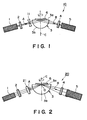
- FIG. 1 is a schematic illustration of a first embodiment of the optical anisotropy measurement apparatus according to the present invention.
- an optical anisotropy measurement apparatus 10 includes a He-Ne laser (light source) 1, a polarizer 2, a spherical segment glass 3 of a hemispherical shape, an analyzer 4 and a photodetector 5, and a liquid crystal cell 6 is formed on a flat surface 3a of the spherical segment glass 3 integrally with the spherical segment glass 3.
- These members are constituted similarly as the corresponding members in the conventional optical anisotropy measurement apparatus described with reference to Figures 12 and 13, and a detailed description thereof is omitted.
- the optical anisotropy measurement apparatus includes a concave lens 11 (as an incident optical system having a negative power) between the polarizer 2 and the spherical segment glass 3, so that an incident beam A (parallel light flux) emitted from the He-Ne laser 1 is diverged by the concave lens 11.
- the concave lens 11 and the spherical segment lens 3 are arranged to constitute an afocal optical system, so that the incident beam A is once diverged by the power of the concave lens 11 and then converged by the power of the spherical segment glass 3 to provide a parallel beam (parallel light flux) incident to the liquid crystal cell 6.
- the afocal optical system means an optical system such that parallel light flux incident to and transmitted through the optical system will make transmitted parallel light flux provided that reflected light is not considered.
- the spherical segment glass 3 may preferably have a shape of a hemisphere or a shape close thereto, and a curvature center in the measurement region or a region close thereto.
- the spherical segment glass 3 may preferably comprise a high refractive index glass having a refractive index of at least 1.7, more preferably at least 1.75, of, e.g., heavy flint glass. It is possible to alternatively use a transparent material free from optical anisotropy other than glass. It is preferred to use a material having a refractive index larger than that of a liquid crystal layer 207 as an object to be examined.
- the light source 1 can be an Ar laser, a semiconductor laser or a beam emission apparatus other than a laser, such as a thermal radiation source, in addition to the He-Ne laser but may preferably comprise an apparatus emitting a beam or light flux that can be condensed.
- the light source 1 may preferably be one free from aberration such as astigmatism and capable of emitting monochromatic light free from chromatic aberration.
- the photodetector 5 may comprise an optical power meter, a photomultiplier, etc., but may preferably be one of a high sensitivity.
- Incident beam A parallel light flux
- the incident beam A diverged light flux
- the incident beam A having entered the spherical segment glass 3 is transformed into a parallel beam (light flux) by the power of the spherical segment glass 3 to be totally reflected at the boundary between an alignment film and a transparent electrode in the liquid crystal cell 6.
- the director of liquid crystal molecules (which is a unit vector representing the orientation of liquid crystal molecules) in the liquid crystal cell 6 is changed relative to the electric field vector of the laser beam A incident to the spherical segment glass 3. Accordingly, corresponding to the rotation angle of the spherical segment glass 3 (i.e., that of the liquid crystal cell 6), the polarization state of the outgoing beam B emitted from the spherical segment glass 3 is changed.
- the pretilt angle determination may be performed roughly in the following manner. If a maximum intensity near a rotation angle 45 deg. (leftmost peak in Figure 14) is represented by its peak l and a minimum intensity near a rotation angle 90 deg. (valley) is represented by its height (altitude) m , a ratio m/l gives a measure of pretilt angle such that a larger m/l ratio represents a larger pretilt angle and vice versa. For example, a ratio m/l of 0.5 roughly represents a pretilt angle of ca. 10 deg. and a ratio m/l of 0 represents a pretilt angle of ca. 0 deg. while it is affected by n o and n e (refractive indices for ordinary and extraordinary rays, respectively) of a liquid crystal concerned.
- the incident beam B enters the liquid crystal cell 6 in the form of parallel light flux so that the incident angle to the boundary of the alignment film and the transparent electrode is free from spreading so that the deterioration of measurement accuracy can be prevented.
- an optical anisotropy measurement apparatus 20 includes a convex lens 21 (i.e., an optical system having a positive power).
- Incident beam A (parallel light flux) emitted from the He-Ne laser 1 is converged by the convex lens 21 to enter the spherical segment glass 3 and further converged by the spherical segment glass 3 to be converged at a point O of intersection of the rotation axis C and the boundary between the alignment film and the transparent electrode (hereinafter simply called a "convergent point").
- the converged incident beam A is totally reflected at the convergent point O.
- An evanescent wave occurring in the total reflection interacts with liquid crystal molecules, returns into the spherical segment glass 3 and forms an outgoing beam B together with the totally reflected light.
- the outgoing beam B becomes a divergent beam and is emitted from the spherical segment glass to pass through the analyzer 4 and enter the photodetector 5.
- the beam diameter of the incident beam A is reduced by the input optical system 21, so that it becomes possible to measure the optical anisotropy of a liquid crystal at a minute region and determine a pretilt angle therefrom.
- the input optical system 21 may be arranged so as to reduce a beam diameter of ca. 1 mm of the incident beam A (parallel light flux) emitted from the He-Ne laser to a beam diameter of ca. 10 ⁇ m at the convergent point.
- the beam diameter at the convergent point O i.e., beam diameter on the measurement surface
- the N.A. number of the input optical system 21. Accordingly, if the N.A. of the input optical system 21 is enlarged, it becomes possible to further reduce the size of the measurement region. If the input optical system 21 is completely free from aberration, it is possible to converge the beam down to the diffraction limit.
- the incident beam A becomes convergent light flux so that the incident angle to the measurement region is accompanied with a spreading, thus being liable to result in a deterioration in measurement accuracy.
- convergent light flux is approximate to parallel light flux in proximity to the convergent point of the convergent light flux, the spreading of the incident angle is not so serious as to deteriorate the measurement accuracy.
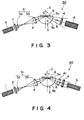
- an optical anisotropy measurement apparatus 20 includes an input optical system 31 comprising two convex lenses 32 and 33 between the polarizer 2 and the spherical segment glass 3.
- the concave lens 32 disposed closer to the polarizer 2 is designed to once converge the incident beam A (parallel light flux) and then convert it into a divergent beam, and the other concave lens 33 is designed to convert the divergent beam into a convergent beam.
- an incident optical system comprising two convex lenses is used to obtain a large N.A. and provide a convergent beam having a reduced beam diameter of 3 - 5 ⁇ m at the convergent point.
- the incident optical system 31 is designed to provide a convergent having passed through the optical system 31 and incident to the spherical segment glass 3 with a wave surface having a curvature radius equal to that of the spherical segment glass 3, so that the incident beam A is converged at the convergent point without being refracted at the incidence to the spherical segment glass 3.
- Figure 3 shows an apparatus including an incident optical system comprising two convex lenses but the incident optical system can comprise three or more lenses not only of convex lenses.
- the beam diameter of the incident beam A can be further reduced by the incident optical system 31, so that it is possible to measure the optical anisotropy of a liquid crystal at a minute region and determine a pretilt angle thereof. More specifically, because of a remarkably improved resolving power, it is possible to detect a fluctuation in pretilt angle, e.g., in one pixel, thereby obtaining data effective for improving the steps for producing a liquid crystal device and the performances of the liquid crystal device per se.
- the incident optical system is disposed so that the incident beam is converged at the boundary between an alignment film and a transparent electrode in the liquid crystal cell 6, but this is not necessary.
- the incident optical system movably in an optical axis direction so that the convergent point can be shifted.
- an optical anisotropy measurement apparatus 40 has a structure similar to that of the above-described optical anisotropy measurement apparatus 30 shown in Figure 3 but is different from the latter in that it further includes a first outgoing optical system 41 comprising a convex lens, which is arranged to convert the outgoing beam B emitted from the spherical segment glass 3 in the form of divergent light flux into parallel light flux.
- a first outgoing optical system 41 comprising a convex lens, which is arranged to convert the outgoing beam B emitted from the spherical segment glass 3 in the form of divergent light flux into parallel light flux.
- An analyzer 4 composed of a polarizing element such as a Glan-Thompson prism generally has an incident angle-dependence. More specifically, when a beam entering the analyzer 4 comprises various angle components, including those providing an incident angle to the analyzer exceeding a tolerable range (ca. ⁇ 7 degrees in the case of a Glan-Thomson prim), the performance of the analyzer 4 is deteriorated, e.g., so as to allow the transmission of a polarization component having a polarization perpendicular to that of the analyzer 4, thus resulting in an inferior measurement accuracy. According to this embodiment, however, the beam entering the analyzer 4 has been transformed into parallel light flux by the outgoing optical system 41, so that such an inferior measurement accuracy bean be obviated.
- the first outgoing optical system 41 need not necessarily be composed of a single convex lens but may comprise plural lenses.
- an optical anisotropy measurement apparatus 50 has a structure similar to that of the above-described optical anisotropy measurement apparatus 40 shown in Figure 4 but is different from the latter in that it further includes a second outgoing optical system 52 comprising a convex lens, which is arranged to convert the parallel light flux outgoing from the analyzer 4 into convergent light flux, thereby reducing the beam diameter of the beam reaching the photodetector 5.
- a second outgoing optical system 52 comprising a convex lens, which is arranged to convert the parallel light flux outgoing from the analyzer 4 into convergent light flux, thereby reducing the beam diameter of the beam reaching the photodetector 5.
- the parallel light flux (beam) is converged by the second outgoing optical system 52 before entering the photodetector 5, so that the light quantity entering the photodetector 5 is increased to provide an improved detecting efficiency.
- the second outgoing optical system 52 need not necessarily be composed of a single convex lens but may comprise plural lenses.
- an optical anisotropy measurement apparatus 60 has a structure similar to that of the above-described optical anisotropy measurement apparatus 50 shown in Figure 5 but is different from the latter in that it includes a third outgoing optical system 61 comprising two convex lens 62 and 63 disposed between the spherical segment glass 3 and the analyzer 4.
- the third outgoing optical system 61 is arranged so that the outgoing beam B emitted from the spherical segment lens 3 is converted first into convergent light flux by the first concave lens 62 and then into parallel light flux by the second concave lens 63.
- the input optical system 31 and the output optical system 61 are arranged as a pair of transversely symmetrical lens systems.
- the beam entering the analyzer 4 is composed of parallel light flux so that the deterioration in measurement accuracy can be obviated. Further, the beam diameter of the outgoing beam B is reduced, so that the light quantity entering the photodetector 5 is increased to provide an improved detection efficiency.
- the third outgoing optical system 61 need not necessarily be composed of two convex lenses but may comprise three or more lenses.
- an optical anisotropy measurement apparatus 70 includes a beam expander (input optical system) 71 comprising two lenses 72 and 73 disposed between the polarizer 2 and the spherical segment glass 3, so that the incident beam A (parallel light flux) is reduced in beam diameter while retaining the parallel flux state.
- a beam expander (input optical system) 71 comprising two lenses 72 and 73 disposed between the polarizer 2 and the spherical segment glass 3, so that the incident beam A (parallel light flux) is reduced in beam diameter while retaining the parallel flux state.
- the incident beam A in the form of linearly polarized light having passed through a polarizer 2 is reduced in beam diameter by the beam expander 71 and incident to the spherical segment glass 3 in a parallel flux state, thereby allowing a measurement of a region on the order of several tens ⁇ m in diameter by using substantially parallel light.
- the beam expander 71 is composed of two convex lenses, but this is not limitative.
- an incident beam to a measurement region in the form of completely parallel flux, e.g., by disposing a concave lens between the beam expander 71 and the spherical segment glass 3.
- Figure 8 shows an eighth embodiment of the optical anisotropy measurement apparatus according to the present invention, whereby the incident beam A is reduced in beam diameter and is caused to be incident to the measurement region in the form of completely parallel light flux.
- members identical to those in Figure 2 are denoted by identical reference numerals and the description thereof may be omitted.
- an optical anisotropy measurement apparatus 80 includes an incident optical system 81 comprising a convex lens disposed between the polarizer 2 and the spherical segment glass 3 so as to reduce the beam diameter of an incident beam A (parallel light flux) having passed through the polarizer 2. Further, the incident optical system 81 and the spherical segment glass 3 are designed to constitute an afocal optical system, whereby the incident beam is reduced in beam diameter and incident to the measurement region while retaining a parallel light flux state. In this instance, when a convex lens having a focal length of 100 - 200 mm is used to constitute the incident optical system 81, the incident beam A entering the measurement region may have a reduced beam diameter on the order of several tens ⁇ m.
- an optical anisotropy measurement apparatus 90 is designed to mount a liquid crystal cell 92 movably or slidably on a flat surface 3a of a spherical segment glass 3.
- the flat surface 3a of the spherical segment glass 3 is coated with a refractive index-matching liquid 91 (of, e.g., methylene iodide-based liquid or arsenic tribromide/disulfide-based liquid) and the liquid crystal cell 92 is mounted on the flat surface 3a via the refractive index-matching liquid 91.
- the refractive index-matching liquid 91 is dammed up by a peripheral rim 3C, which can however be omitted depending on the quantity and/or the viscosity of the liquid.
- An incident beam A emitted from a He-Ne laser 1 passes through the polarizer 2, enters the spherical segment glass 3 through its spherical surface 3b and is totally reflected within the liquid crystal cell 92 to form an outgoing beam B.
- the beam B is emitted through the spherical surface of the spherical segment 3 to pass through an analyzer 4 and enters a photodetector 5.
- the liquid crystal cell 92 comprises a pair of glass substrates 94a and 94b having thereon transparent electrodes 95a, 95b of, e.g., ca. 0.1 ⁇ m-thick ITO films having a refractive index of ca. 1.95, and alignment films 96a, 96b of, e.g., ca. 0.05 ⁇ m-thick polyimide films having a refractive index of ca. 1.6, respectively, and a liquid crystal 93 injected between the alignment films 96a and 96b.
- the liquid crystal cell 92 is held within a liquid crystal cell holder 97 and on the flat surface 3a of the spherical segment glass 3 so that the lower glass substrate 94b thereof is dipped within the refractive index-matching liquid 91.
- the liquid crystal cell holder 97 is supported movably by a spherical segment glass holder 98 also holding the spherical segment glass 3 and driven at a high accuracy by a drive mechanism (not shown).
- a drive mechanism not shown
- the spherical segment glass 3 may be fixed, and the liquid crystal cell 92 may be moved or slided along the flat surface 3a of the spherical segment glass 3.
- the spherical segment glass holder 98 is equipped with a micrometer 99, by which the measurement position of the liquid crystal cell 92 can be accurately confirmed.
- a micrometer 99 may be provided in a plurality, e.g., so as to have axes crossing each other at right angles, thereby allowing a two-dimensional position confirmation of the liquid crystal cell 92.
- the spherical segment glass holder 98 is provided with a rotation apparatus (not shown) for rotating the spherical segment glass 3 about its central axis (rotation axis) C, so that the spherical segment glass 3 and the liquid crystal cell 92 are integrally rotated about the rotation axis C.
- the spherical segment glass 3 may be composed of a glass material having a refractive index almost identical to that of the glass substrate 94b of the liquid crystal cell 92, and the refractive index-matching liquid may also comprise a liquid (e.g., methylene iodide-based liquid, etc. as described above) having a refractive index almost identical to that of the glass substrate 94b.
- almost identical refractive indexes mean such a closeness of refractive index as to avoid a total reflection of the incident beam A at the boundary between the spherical segment glass 3 and the matching liquid 91, and at the boundary between the matching liquid 91 and the liquid crystal cell 92, and may be determined depending on the incident angle.
- the refractive index difference between the spherical segment glass 3 and the matching liquid 91 and the refractive index difference between the matching liquid 91 and the glass substrate 94 may preferably be within a range of ⁇ 0.05, respectively.
- the spherical segment glass 3 and the glass substrate 94b may preferably comprise a high-refractive index glass, such as heavy flint glass, having a refractive index of at least 1.7, more preferably at least 1.75. It is also possible to use a transparent material free from optical anisotropy instead of glass. In this instance, a material having a larger refractive index than the liquid crystal layer 93 is suitably used.
- the glass substrate 94a can also be composed of a high refractive index glass.
- the flat surface 3a of the spherical segment glass 3 has a larger area than the liquid crystal cell but can have a smaller area than the latter.
- the optical anisotropy (and pretilt angle) of the liquid crystal layer 93 may be measured by using the above-mentioned optical anisotropy measurement apparatus 90 as follows.
- the incident beam A emitted from the He-Ne laser passes through the polarizer 2 to be linearly polarized light and enters the spherical segment glass 3 through the spherical surface 3b.
- the incident beam A having entered the spherical segment glass 3 passes through the flat surface 3a of the spherical segment glass 3 and the refractive index-matching liquid 91 to enter the liquid crystal cell 92.
- the spherical segment glass 3 has a refractive index almost identical to the glass substrate 94b of the liquid crystal cell 92, and the refractive index-matching liquid 91 also has a refractive index almost identical to those of the glass substrate 94b and the spherical segment glass 3, the incident beam A having entered the spherical segment glass is caused to enter the glass substrate 94b without causing refraction.
- the incident beam A having entered the glass substrate 94b is totally reflected at the boundary between the transparent electrode 95b and the. alignment film 96b.
- an evanescent wave occurs, penetrates into the liquid crystal layer 93 to interact with liquid crystal molecules and returns to the spherical segment glass 3 to form an outgoing beam B together with the totally reflected light.
- the outgoing between B emitted from the spherical surface 3b of the spherical segment 3 is once conveyed to pass through the analyzer 4 having a polarization direction perpendicular to that of the polarizer 2, whereby only a light component having a polarization direction perpendicular to the incident beam A reaches the photodetector 5.
- liquid crystal cell 92 is mounted on the flat surface 3a of the spherical segment glass 3 in a state that the glass substrate 94b thereof is dipped in the refractive index-matching liquid 1
- an actual liquid crystal cell incorporated in a display panel, etc., or a liquid crystal cell produced through steps very close to those for production of an actual liquid crystal cell e.g., one produced in an identical structure except for using a high-refractive index glass sheet for the substrate
- the liquid crystal cell 92 is held in the liquid crystal cell holder 97, which can be moved by a drive mechanism (not shown) to move the liquid crystal cell 92 along the flat surface 3a of the spherical segment glass 3 while accurately measuring the moving distance of the liquid crystal cell holder 97 to confirm the measurement position of the liquid crystal cell 92, whereby it is possible to measure a pretilt angle at a desired position of the liquid crystal layer 93.
- the pretilt angle of an actual liquid crystal cell or a liquid crystal prepared through steps close to those for production of an actual liquid crystal cell can be measured at desired position, it is possible to obtain information very important for improving the steps for production of a liquid crystal device or the performance of a liquid crystal device per se. Further, by incorporating the optical anisotropy measurement apparatus according to this embodiment in an actual production line for a liquid crystal devices to produce a liquid crystal device, it becomes possible to produce high-quality liquid crystal devices without producing an unsatisfactory product.
- optical anisotropy measurement apparatus 90 can be combined with various optical systems used in the first to eighth embodiments to obtain effects similar to those in such embodiments.
- an optical anisotropy measurement apparatus 100 includes a convex lens 101 (incident optical system) between the polarizer 2 and the spherical segment glass 3.
- the other structures are similar to those in the optical anisotropy measurement apparatus 90 in the ninth embodiment.
- the size of the measurement region for measurement of a pretilt angle in a liquid crystal layer can be reduced to several pm to several tens ⁇ m by converging the incident beam A in proximity to the measurement region, so that a pretilt angle of a liquid crystal layer in a desired position in one pixel can be measure to evaluate the irregularity in pretilt angle in a pixel.
- the pretilt angle of an actual liquid crystal cell or a liquid crystal prepared through steps close to those for production of an actual liquid crystal cell can be measured in a small region at desired position, it is possible to obtain information very important for improving the steps for production of a liquid crystal device or the performance of a liquid crystal device per se. Further, by incorporating the optical anisotropy measurement apparatus according to this embodiment in an actual production line for a liquid crystal devices to produce a liquid crystal device, it becomes possible to produce high-quality liquid crystal devices without producing an unsatisfactory product.
Applications Claiming Priority (6)
| Application Number | Priority Date | Filing Date | Title |
|---|---|---|---|
| JP12104/95 | 1995-01-27 | ||
| JP1210495 | 1995-01-27 | ||
| JP1210395 | 1995-01-27 | ||
| JP12103/95 | 1995-01-27 | ||
| JP203385/95 | 1995-08-09 | ||
| JP20338595 | 1995-08-09 |
Publications (2)
| Publication Number | Publication Date |
|---|---|
| EP0724147A2 true EP0724147A2 (de) | 1996-07-31 |
| EP0724147A3 EP0724147A3 (de) | 1997-05-07 |
Family
ID=27279702
Family Applications (1)
| Application Number | Title | Priority Date | Filing Date |
|---|---|---|---|
| EP96300507A Withdrawn EP0724147A3 (de) | 1995-01-27 | 1996-01-25 | Verfahren und Vorrichtung zur Messung der optischen Anisotropie |
Country Status (3)
| Country | Link |
|---|---|
| US (1) | US5838453A (de) |
| EP (1) | EP0724147A3 (de) |
| KR (1) | KR100226016B1 (de) |
Cited By (3)
| Publication number | Priority date | Publication date | Assignee | Title |
|---|---|---|---|---|
| EP0805347A2 (de) * | 1996-04-30 | 1997-11-05 | Fuji Photo Film Co., Ltd. | Oberflächen-Plasmon-Sensor |
| EP0811835A1 (de) * | 1996-06-05 | 1997-12-10 | Canon Kabushiki Kaisha | Vorrichtung und Verfahren zur Messung optischer Anisotropie |
| CN110542541A (zh) * | 2019-08-08 | 2019-12-06 | 歌尔股份有限公司 | 一种镜片反射率测量方法及测量装置 |
Families Citing this family (6)
| Publication number | Priority date | Publication date | Assignee | Title |
|---|---|---|---|---|
| JP2000081371A (ja) * | 1998-09-07 | 2000-03-21 | Nec Corp | 薄膜分子配向評価方法、評価装置及び記録媒体 |
| JP2006228930A (ja) | 2005-02-17 | 2006-08-31 | Canon Inc | 測定装置及びそれを搭載した露光装置 |
| JP5709368B2 (ja) * | 2009-11-04 | 2015-04-30 | キヤノン株式会社 | 生体情報取得装置 |
| US20120133943A1 (en) * | 2010-11-29 | 2012-05-31 | Norman Henry Fontaine | Systems And Methods For Multi-Wavelength SPR Biosensing With Reduced Chromatic Aberration |
| CN104111548A (zh) * | 2014-06-30 | 2014-10-22 | 京东方科技集团股份有限公司 | 用于阵列基板检测设备的光学系统及阵列基板检测设备 |
| RU2629700C1 (ru) * | 2016-10-20 | 2017-08-31 | Федеральное государственное бюджетное научное учреждение "Федеральный исследовательский центр Институт прикладной физики Российской академии наук" (ИПФ РАН) | Способ определения параметра оптической анизотропии кубического монокристалла, относящегося к классу симметрии m3m, 43m или 432 |
Citations (3)
| Publication number | Priority date | Publication date | Assignee | Title |
|---|---|---|---|---|
| DE4211467A1 (de) * | 1992-04-06 | 1993-10-07 | Zeiss Carl Jena Gmbh | Verfahren zur Bestimmung räumlicher Anisotropiezustände eines niedrig orientierten zweiachsigen Objektes |
| EP0575132A1 (de) * | 1992-06-17 | 1993-12-22 | Hewlett-Packard Company | Optische Messvorrichtung |
| JPH0634530A (ja) * | 1992-07-20 | 1994-02-08 | Hitachi Ltd | 非線形光学定数測定法 |
Family Cites Families (4)
| Publication number | Priority date | Publication date | Assignee | Title |
|---|---|---|---|---|
| SU989403A1 (ru) * | 1980-07-14 | 1983-01-15 | Предприятие П/Я Р-6681 | Способ контрол главных показателей преломлени одноосных кристаллов |
| US4516855A (en) * | 1981-04-03 | 1985-05-14 | International Business Machines Corporation | Method and apparatus for determining the polarization state of a light wave field |
| US5108185A (en) * | 1987-06-12 | 1992-04-28 | Boston University | Apparatus for measuring reflectivity |
| CA1321488C (en) * | 1987-08-22 | 1993-08-24 | Martin Francis Finlan | Biological sensors |
-
1996
- 1996-01-24 US US08/590,814 patent/US5838453A/en not_active Expired - Fee Related
- 1996-01-25 EP EP96300507A patent/EP0724147A3/de not_active Withdrawn
- 1996-01-27 KR KR1019960001833A patent/KR100226016B1/ko not_active IP Right Cessation
Patent Citations (3)
| Publication number | Priority date | Publication date | Assignee | Title |
|---|---|---|---|---|
| DE4211467A1 (de) * | 1992-04-06 | 1993-10-07 | Zeiss Carl Jena Gmbh | Verfahren zur Bestimmung räumlicher Anisotropiezustände eines niedrig orientierten zweiachsigen Objektes |
| EP0575132A1 (de) * | 1992-06-17 | 1993-12-22 | Hewlett-Packard Company | Optische Messvorrichtung |
| JPH0634530A (ja) * | 1992-07-20 | 1994-02-08 | Hitachi Ltd | 非線形光学定数測定法 |
Non-Patent Citations (4)
| Title |
|---|
| JAPANESE JOURNAL OF APPLIED PHYSICS, PART 1 (REGULAR PAPERS & SHORT NOTES), JAN. 1986, JAPAN, vol. 25, no. 1, ISSN 0021-4922, pages 1-7, XP002026176 YAMASHITA M: "Dependence of temporal behavior of conoscopic figures in nematic liquid crystals on film thickness" * |
| JAPANESE JOURNAL OF APPLIED PHYSICS, PART 1 (REGULAR PAPERS & SHORT NOTES), JULY 1983, JAPAN, vol. 22, no. 7, ISSN 0021-4922, pages 1080-1091, XP002026175 TAKEZOE H ET AL: "Experimental studies on reflection spectra in monodomain cholesteric liquid crystal cells: total reflection, subsidiary oscillation and its beat or swell structure" * |
| PATENT ABSTRACTS OF JAPAN vol. 018, no. 250 (P-1736), 12 May 1994 & JP 06 034530 A (HITACHI LTD), 8 February 1994, * |
| SOVIET INVENTIONS ILLUSTRATED Section EI, Week 8344 Derwent Publications Ltd., London, GB; Class S03, AN 83-807176 XP002026177 & SU 989 403 A (MOROZOV V N) , 15 January 1983 * |
Cited By (7)
| Publication number | Priority date | Publication date | Assignee | Title |
|---|---|---|---|---|
| EP0805347A2 (de) * | 1996-04-30 | 1997-11-05 | Fuji Photo Film Co., Ltd. | Oberflächen-Plasmon-Sensor |
| EP0805347A3 (de) * | 1996-04-30 | 1998-08-05 | Fuji Photo Film Co., Ltd. | Oberflächen-Plasmon-Sensor |
| US5907408A (en) * | 1996-04-30 | 1999-05-25 | Fuji Photo Film Co., Ltd. | Surface plasmon sensor |
| EP0811835A1 (de) * | 1996-06-05 | 1997-12-10 | Canon Kabushiki Kaisha | Vorrichtung und Verfahren zur Messung optischer Anisotropie |
| US6088115A (en) * | 1996-06-05 | 2000-07-11 | Canon Kabushiki Kaisha | Apparatus and method for measuring optical anisotropy |
| CN110542541A (zh) * | 2019-08-08 | 2019-12-06 | 歌尔股份有限公司 | 一种镜片反射率测量方法及测量装置 |
| CN110542541B (zh) * | 2019-08-08 | 2021-04-09 | 歌尔光学科技有限公司 | 一种镜片反射率测量方法及测量装置 |
Also Published As
| Publication number | Publication date |
|---|---|
| EP0724147A3 (de) | 1997-05-07 |
| KR960029829A (ko) | 1996-08-17 |
| US5838453A (en) | 1998-11-17 |
| KR100226016B1 (ko) | 1999-10-15 |
Similar Documents
| Publication | Publication Date | Title |
|---|---|---|
| KR101441876B1 (ko) | 광학이방성 패러미터 측정 방법 및 측정 장치 | |
| JP2003520955A (ja) | ブルースター角プリズム逆反射体に基づく共振空洞リングダウン分光のための改善されたモードマッチング | |
| US6483584B1 (en) | Device for measuring the complex refractive index and thin film thickness of a sample | |
| US6678433B2 (en) | Apparatus and method for measuring residual stress and photoelastic effect of optical fiber | |
| US5838453A (en) | Apparatus and method for measuring optical anisotropy | |
| US6215549B1 (en) | Apparatus for measuring optical characteristics | |
| US5903352A (en) | Apparatus and method for measuring optical anisotropy | |
| KR101196925B1 (ko) | 투명한 또는 부분적으로 투명한 층의 굴절률을 3차원적으로결정하기 위한 방법 및 장치 | |
| EP1202033B1 (de) | Spektralellipsometer | |
| JP3063843B2 (ja) | 液晶初期配向角測定法及び液晶初期配向角測定装置 | |
| US6088115A (en) | Apparatus and method for measuring optical anisotropy | |
| CN1206521C (zh) | 用于光导纤维的残余应力测量装置 | |
| CN1431477A (zh) | 检测表面形状的点衍射干涉仪 | |
| US4932780A (en) | Interferometer | |
| JP3363743B2 (ja) | 光学的異方性測定装置及びそれを用いた光学的異方性測定方法 | |
| Grindel | Testing collimation using shearing interferometry | |
| JP3342281B2 (ja) | 光学的異方性測定装置、光学的異方性測定方法、及び該光学的異方性測定装置を用いた液晶デバイスの製造方法 | |
| GB2118304A (en) | Detecting surface deviations | |
| JPH09243510A (ja) | 光学的異方性測定装置及びその測定方法 | |
| KR20100033164A (ko) | 마이크로 스폿 분광타원계 | |
| JP3397559B2 (ja) | 光学的異方性測定装置及び光学的異方性測定方法 | |
| US7952712B2 (en) | Method for detecting equatorial plane | |
| Chatterjee et al. | Simple technique for the generation of plane surface normal to optic axis direction of uniaxial crystal | |
| JPH05264440A (ja) | 偏光解析装置 | |
| CN215833253U (zh) | 一种基于光束偏转器的角度调制型spr传感器及spr检测设备 |
Legal Events
| Date | Code | Title | Description |
|---|---|---|---|
| PUAI | Public reference made under article 153(3) epc to a published international application that has entered the european phase |
Free format text: ORIGINAL CODE: 0009012 |
|
| AK | Designated contracting states |
Kind code of ref document: A2 Designated state(s): CH DE FR GB IT LI NL SE |
|
| PUAL | Search report despatched |
Free format text: ORIGINAL CODE: 0009013 |
|
| AK | Designated contracting states |
Kind code of ref document: A3 Designated state(s): CH DE FR GB IT LI NL SE |
|
| 17P | Request for examination filed |
Effective date: 19970917 |
|
| 17Q | First examination report despatched |
Effective date: 20020430 |
|
| STAA | Information on the status of an ep patent application or granted ep patent |
Free format text: STATUS: THE APPLICATION IS DEEMED TO BE WITHDRAWN |
|
| 18D | Application deemed to be withdrawn |
Effective date: 20020911 |