EP0724077B1 - Scroll type compressor and method for manufacturing the same - Google Patents
Scroll type compressor and method for manufacturing the same Download PDFInfo
- Publication number
- EP0724077B1 EP0724077B1 EP96100689A EP96100689A EP0724077B1 EP 0724077 B1 EP0724077 B1 EP 0724077B1 EP 96100689 A EP96100689 A EP 96100689A EP 96100689 A EP96100689 A EP 96100689A EP 0724077 B1 EP0724077 B1 EP 0724077B1
- Authority
- EP
- European Patent Office
- Prior art keywords
- scroll
- weight
- aluminum alloy
- scrolls
- temperature
- Prior art date
- Legal status (The legal status is an assumption and is not a legal conclusion. Google has not performed a legal analysis and makes no representation as to the accuracy of the status listed.)
- Expired - Lifetime
Links
Images


Classifications
-
- F—MECHANICAL ENGINEERING; LIGHTING; HEATING; WEAPONS; BLASTING
- F04—POSITIVE - DISPLACEMENT MACHINES FOR LIQUIDS; PUMPS FOR LIQUIDS OR ELASTIC FLUIDS
- F04C—ROTARY-PISTON, OR OSCILLATING-PISTON, POSITIVE-DISPLACEMENT MACHINES FOR LIQUIDS; ROTARY-PISTON, OR OSCILLATING-PISTON, POSITIVE-DISPLACEMENT PUMPS
- F04C18/00—Rotary-piston pumps specially adapted for elastic fluids
- F04C18/02—Rotary-piston pumps specially adapted for elastic fluids of arcuate-engagement type, i.e. with circular translatory movement of co-operating members, each member having the same number of teeth or tooth-equivalents
-
- B—PERFORMING OPERATIONS; TRANSPORTING
- B22—CASTING; POWDER METALLURGY
- B22D—CASTING OF METALS; CASTING OF OTHER SUBSTANCES BY THE SAME PROCESSES OR DEVICES
- B22D27/00—Treating the metal in the mould while it is molten or ductile ; Pressure or vacuum casting
- B22D27/09—Treating the metal in the mould while it is molten or ductile ; Pressure or vacuum casting by using pressure
-
- C—CHEMISTRY; METALLURGY
- C22—METALLURGY; FERROUS OR NON-FERROUS ALLOYS; TREATMENT OF ALLOYS OR NON-FERROUS METALS
- C22C—ALLOYS
- C22C21/00—Alloys based on aluminium
- C22C21/02—Alloys based on aluminium with silicon as the next major constituent
-
- F—MECHANICAL ENGINEERING; LIGHTING; HEATING; WEAPONS; BLASTING
- F04—POSITIVE - DISPLACEMENT MACHINES FOR LIQUIDS; PUMPS FOR LIQUIDS OR ELASTIC FLUIDS
- F04C—ROTARY-PISTON, OR OSCILLATING-PISTON, POSITIVE-DISPLACEMENT MACHINES FOR LIQUIDS; ROTARY-PISTON, OR OSCILLATING-PISTON, POSITIVE-DISPLACEMENT PUMPS
- F04C18/00—Rotary-piston pumps specially adapted for elastic fluids
- F04C18/02—Rotary-piston pumps specially adapted for elastic fluids of arcuate-engagement type, i.e. with circular translatory movement of co-operating members, each member having the same number of teeth or tooth-equivalents
- F04C18/0207—Rotary-piston pumps specially adapted for elastic fluids of arcuate-engagement type, i.e. with circular translatory movement of co-operating members, each member having the same number of teeth or tooth-equivalents both members having co-operating elements in spiral form
- F04C18/0246—Details concerning the involute wraps or their base, e.g. geometry
-
- F—MECHANICAL ENGINEERING; LIGHTING; HEATING; WEAPONS; BLASTING
- F04—POSITIVE - DISPLACEMENT MACHINES FOR LIQUIDS; PUMPS FOR LIQUIDS OR ELASTIC FLUIDS
- F04C—ROTARY-PISTON, OR OSCILLATING-PISTON, POSITIVE-DISPLACEMENT MACHINES FOR LIQUIDS; ROTARY-PISTON, OR OSCILLATING-PISTON, POSITIVE-DISPLACEMENT PUMPS
- F04C2230/00—Manufacture
- F04C2230/20—Manufacture essentially without removing material
- F04C2230/21—Manufacture essentially without removing material by casting
-
- F—MECHANICAL ENGINEERING; LIGHTING; HEATING; WEAPONS; BLASTING
- F05—INDEXING SCHEMES RELATING TO ENGINES OR PUMPS IN VARIOUS SUBCLASSES OF CLASSES F01-F04
- F05C—INDEXING SCHEME RELATING TO MATERIALS, MATERIAL PROPERTIES OR MATERIAL CHARACTERISTICS FOR MACHINES, ENGINES OR PUMPS OTHER THAN NON-POSITIVE-DISPLACEMENT MACHINES OR ENGINES
- F05C2201/00—Metals
- F05C2201/90—Alloys not otherwise provided for
- F05C2201/903—Aluminium alloy, e.g. AlCuMgPb F34,37
Definitions
- the present invention relates to a scroll type compressor and its manufacturing method and particularly to a compressor provided with scrolls molded by a high speed die casting method.
- a typical scroll type compressor is provided with a fixed scroll and a movable scroll.
- Each of the fixed and movable scrolls has a base plate and a spiral element.
- the spiral elements of the two scrolls are engaged with each other to define a compression chamber therebetween.
- the movable scroll orbits around the center axis of the fixed scroll as a shaft, which is coupled to the movable scroll, rotates. This moves the compression chamber from the outer circumferences of the spiral elements to the centers of the spiral elements to compress gas.
- Relatively large components such as a housing which retains the two scrolls, are die cast from an aluminum alloy to decrease the weight of the compressor while maintaining its strength.
- the scrolls in particular, are typically manufactured by low speed die casting.
- Table 1 shows the typical molding conditions when using a low speed die casting method. Molding Condition of Scrolls Formed By Low Speed Die Casting Molding Conditions Metal Material AC8C (aluminum alloy as defined in JIS H5202) Molten Metal Temperature (°C) 700-730 Mold Temperature (°C) 150-200 Injection Speed (m/s) 0.05-0.3 Pressurizing Force (kg/cm 2 ) 800-1000 Cycle Time (sec.) 80-100
- the slow injection speed of the molten metal, and the high pressurizing force against the molten metal prevents air surrounding the mold from entering the mold. Hence, the formation of gas bubbles (air pockets) is suppressed. This produces high-quality scrolls.
- the slow injection speed and the long cycle time results in low productivity and increases manufacturing costs.
- High speed die casting is known as a molding method having high productivity.
- heat treatment solution annealing
- the high injection speed draws in a large amount of air into the mold during injection of the molten metal and thus forms gas bubbles in the scroll.
- solution annealing is performed on scrolls having air pockets, the air inside the pockets expands. This leads to the formation of blisters in the scrolls, and such scrolls are defective. Therefore, scrolls, which require high strength and wear resistance, are inevitably molded by the low speed die casting method.
- the reference EP 0 508 426 from which the invention starts out relates to a sintered aluminium alloy for a scroll type compressor, which is composed of Cu, Si, Mg, Fe and Mn, among others.
- the aluminium alloy disclosed in this reference shall serve to produce a material of high strength and high toughness, particularly of high wear resistance.
- the reference US-4,908,077 also relates to a scroll type compressor made of an aluminium alloy by means of which a fine microstructure free of inner defects and porosities can be produced. This shall serve to achieve a higher heat resistance.
- this reference provides the addition of 8.5 to 10.5% of silicon, wherein the average particle diameter of the eutectic silicon is in the range of 2 to 8 ⁇ m.
- the document JP 41 36 492 discloses a movable scroll as subject-matter, which consists of an aluminium alloy.
- the aluminium alloy has, among others, the alloy component "Si" with a wt.% of 8.5 to 2.4.
- the reference JP 62 127 447 describes a scroll type compressor, the scroll parts of which are made of an aluminium alloy.
- the alloy comprises "Cu" at a wt.% of 1.5 to 3.
- a front housing 1 is secured to the front side (left side of drawing) of a fixed scroll 2 by bolts (not shown).
- a rear housing 3 is secured to the rear side of the fixed scroll by bolts (not shown).
- a shaft 4 is rotatably supported in the front housing by a main bearing 5.
- An eccentric pin 6 protrudes from the inner end of the shaft 4.
- a bushing 7 is rotatably and slidably supported by the eccentric pin 6.
- a bearing 8 is fit onto the bushing 7.
- the fixed scroll 2 has a base plate 9 and a spiral element 10 formed integrally on the inner side of the plate 9.
- the outer wall 25 serves as a housing which accommodates the spiral element 10.
- a movable scroll 11 is accommodated in the front housing 1.
- the movable scroll 11 also has a base plate 12 and a spiral element 13 formed integrally on the inner side of the plate 12. As shown in Figs. 1 and 2, the spiral element 10 of the fixed scroll 2 is engaged with the spiral element 13 of the movable scroll 11. The end face of the spiral element 10 contacts the base plate 12 of the movable scroll 11 while the end face of the spiral element 13 contacts the base plate 9 of the fixed scroll 2.
- a suction chamber 16, into which refrigerant gas is drawn, is defined at the outer side of the spiral elements 10, 13.
- a compression chamber 17 is defined between the spiral elements 10, 13.
- a discharge outlet 18 is formed in the center of the base plate 9 of the fixed scroll 2. The outlet 18 connects the compression chamber 17 with a discharge chamber 19 defined in the rear housing 3.
- a suction valve 20 is provided at the outer end of the outlet 18.
- a stopper 21 regulates the opening of the valve 20.
- the bushing 7 is supported by the bearing 8 to allow relative rotation with a boss 22.
- a known anti-rotation mechanism 24 is provided between the front housing 1 and the movable scroll 11. The anti-rotation mechanism 24 prohibits the movable scroll 11 from rotating about its own axis. Rotation of the shaft 4 causes the eccentric pin 6 to move the movable scroll 11 along an orbit around the center axis of the shaft 4 by way of the bushing 7 and the bearing 8. The movement of the movable scroll 11 introduces refrigerant gas into the suction chamber 16 and then compresses the gas in the compression chamber 17. The refrigerant gas is then discharged into the discharge chamber 19 from the discharge outlet 18 and is finally externally discharged from a discharge port 26.
- the fixed scroll 2 is molded using a high speed die casting method.
- the molding conditions of the scroll 2 are shown in Table 2. Molding Condition of Scrolls Formed By High Speed Die Casting Molding Conditions Metal Material Material used in the present embodiment (refer to Table 4) Molten Metal Temperature (°C) 700-730 Mold Temperature (°C) 150-200 Injection Speed (m/s) 1-5 Pressurizing Force (kg/cm 2 ) 700 Cycle Time (sec.) 60
- the fixed scroll 2 is formed by first preheating molds 31, 32 to a temperature within the range of 150 to 200°C, preferably at 180°C.
- a modification agent (grain refining agent)
- 0.01 to 0.20% by weight of titanium (Ti) is applied to the molten aluminum alloy (hereafter referred to as molten metal), the temperature of which is within the range of 700 to 730°C, preferably at 700°C.
- molten metal molten aluminum alloy
- titanium preferably added to an aluminum ingot and then both are melted together.
- the molten metal is then charged into a cavity 33 at an injection speed of 1 to 5 m/s, preferably 5 m/s.
- the molds 31, 32 are then closed for a predetermined period of time.
- a portion of the molded product is pressurized before the molten metal solidifies in the cavity 33.
- the sectional pressurization is performed by a first squeeze rod 35 and a second squeeze rod 37 two seconds after the molten metal is injected into the cavity.
- the first squeeze rod 35 is moved axially in a slide sheath 36 which forms the discharge port 26, and the second squeeze rod 37 is moved axially in a section of the mold 32 that corresponds to the discharge chamber (center portion of the fixed scroll 2) during pressurization of the molten metal.
- the squeeze rods 35, 37 are moved by hydraulic pressure.
- the sectional pressurization of these two mold portions by the squeeze rods 35, 37 ensures the supply of molten metal to portions in the cavity 33 where air tends to collect.
- the fixed scroll 2 is rapidly cooled immediately after removing the scroll 2 from the molds 31, 32.
- the scroll 2 undergoes a quenching treatment.
- the temperature of the scroll is approximately 400°C.
- This treatment is continued until the temperature of the scroll 2 is lowered to approximately 80°C from 400°C.
- the scroll 2 is then heated from 80°C to approximately 200°C for about two hours to subject it to an artificial aging treatment.
- the scroll 2 is machined by an NC machine tool to obtain the predetermined shape.
- the movable scroll 11 is formed in the same manner as the fixed scroll 2.
- Sectional pressurization is preferably conducted only at the center portion of the base plate 12 during molding of the movable scroll 11. Nevertheless, if desired, sectional pressurization may be conducted on two portions, as in the same manner with the fixed scroll 2, to enhance the charging ratio.
- the scrolls 2, 11 molded in the above manner are made of an aluminum alloy.
- the composition of this material is shown in Table 3 in comparison with the aluminum alloy used in the prior art.
- the content ratios of each component in the present invention are as follows: copper (Cu) 4.0 to 5.0% by weight, silicon (Si) 9.0 to 12.0% by weight, magnesium (Mg) 0.5 to 1.5% by weight, iron (Fe) 0.6 to 1.0% by weight, zinc (Zn) 0.03% by weight, manganese (Mn) 0.03% by weight, and nickel (Ni) 0.03% by weight.
- the remainder is composed by aluminum (Al).
- Preferable contents of each component are as follows: Cu 4.5% by weight, Si: 10.5% by weight, Mg: 1.0% by weight, Fe: 0.83 by weight, and Zn, Mn and Ni: 0.03% by weight for each.
- Table 4 shows the mechanical characteristics of a scroll made from an alloy of the composition of Table 3.
- Mechanical Characteristics of the Scroll Tensile Strength 240-300 kg/mm 2 Brinell Hardness (H B ) 100-120 Coefficient of Thermal Expansion 2.1 x 10 -7 Heat Deformation 1.5 x 10 -4 % or less (180°C x 100 hrs.)
- Fig. 4 shows a graph illustrating the relationship between the content of Cu and the tensile strength of the scroll when the scroll is molded from an aluminum alloy with 5% or less of Cu applied to Al.
- the graph also shows the same relationship with heat treatment performed on the scroll after molding and shows changes in tensile strength.
- Line a-b in Fig. 4 shows the alteration of tensile strength with respect to the Cu content ratio in a scroll on which slow cooling (annealing) is performed.
- annealing slow cooling
- Line x-c shows the tensile strength of the scroll on which quenching is performed after molding.
- the tensile strength increases at a higher rate than when compared to the line x-b. This is because the higher the content ratio of Cu is, the higher the strength of the material as a solid solution becomes when quenching is performed.
- line x-d corresponds to the heat treatment performed on the scrolls 2, 11. Artificial aging is performed on the scrolls 2, 11 by heating them at approximately 200°C for about two hours after quenching.
- line x-d By comparing line x-d with line x-c, it is apparent that the tensile strength becomes greater when heat treatment is conducted on the molded product. This is because a super-saturated solid solution of Cu produced in Al during quenching is stabilized by the artificial aging, which in turn increases the tensile strength of the super-saturated solid solution.
- stabilized super-saturated solid solution refers to a state where a phase of Cu solidified in Al and a phase of CuAl 2 coexists. Although the phase of CuAl 2 does not deposit just by quenching, the two phases exist in the scrolls 2,11 when artificial aging is performed. This results in the stabilization of the super-saturated solid solution and increases the tensile strength of the scrolls 2, 11.
- Sectional pressurization during molding ensures the supply of molten metal to the portions where air pockets tend to form and improves the charging rate of the molten metal into the cavity 33. This reduces the formation of gas bubbles in the scrolls 2, 11 after completion of molding. As a result, it is possible to employ high speed die casting, which has a short cycle time, to mold the scrolls 2, 11 while maintaining sufficient hardness and wear resistance of the scrolls 2, 11. Accordingly, a great reduction in the manufacturing cost of the compressor is possible.
- the composition of the aluminum alloy used to mold the scrolls 2, 11 of the present embodiment is as shown in Table 3.
- Mechanical strength and hardness of the aluminum alloy, or the scrolls 2, 11, are improved by Cu.
- the content ratio of Cu is lower than 4.0% by weight, the mechanical strength and hardness of the scrolls 2, 11 is insufficient, and when the ratio is higher than 5.0% by weight, the scrolls 2, 11 become brittle.
- Flowability of the molten metal during the molding and wear resistance of the molded product are enhanced by Si.
- the content ratio of Si is lower than 9.0% by weight, the coefficient of thermal expansion becomes large.
- the content ratio of Si is higher than 12.0% by weight, the Si crystallizes as primary crystals. This lowers the machinability of the molded product. It also reduces the toughness and fatigue strength of the molded product.
- Si exceeds 12.0% by weight, the dissolution temperature of the molten metal becomes high. Therefore, the H 2 gas in the air may be absorbed in the molten metal, and oxides may be produced. Thus, there is a possibility that the molded product may become defective during molding.
- Mg causes Mg 2 Si to be deposited. This increases the mechanical strength and hardness of the molded product.
- the content ratio of Mg is lower than 0.5% by weight, the mechanical strength and hardness of the molded product is insufficient.
- the content ratio of Mg exceeds 1.5% by weight, there is a tendency of Mg oxides being produced. This lowers the flowability of the molten metal.
- Burning and eroding of the molds caused by the molten metal during molding is prevented by Fe.
- the content ratio of Fe is lower than 0.6% by weight, the effect of the Fe is insufficient.
- the content ratio of Fe exceeds 1.0% by weight, Al-Fe base crystal are produced. This lowers the strength of the molded product.
- the aluminum alloy contains 0.03% by weight of Zn, Mn, and Ni each. This improves the strength and toughness of the scrolls 2, 11.
- the scrolls 2, 11 are formed of the aluminum alloy containing 4.0 to 5.0% by weight of Cu, 9.0 to 12.0% by weight of Si, 0.5 to 1.5% by weight of Mg, and 0.6 to 1.0% by weight of Fe. Accordingly, it is possible to sufficiently use the characteristics of each element.
- the temperature during artificial aging (approximately 200°C) of the scrolls 2, 11 is higher than the temperature in the compressor during its operation (approximately 180°C, refer to Table 4).
- dimensional change of the scrolls 2, 11 is small.
- Figs. 5 and 6 are graphs comparing the hardness and the tensile strength of a molded product of the present invention and a prior art molded product.
- quenching and aging treatments are conducted on the scrolls 2, 11 after they are molded from an alloy of the composition shown in Table 3.
- AC8C which is an alloy material
- a heat treatment defined as T5 and T6 by JIS H5202 is conducted on the scrolls.
- T5 treatment quenching is not performed on the scrolls. Only artificial aging is performed.
- T6 treatment after quenching, aging is conducted for a few hours at a temperature between the range of 150 to 180°C.
- the molded product of the present invention is superior in hardness and tensile strength when compared with a prior art molded product on which T5 treatment had been conducted and has the same hardness as the prior art molded product on which T6 had been conducted.
- Na (0.001% by weight to 0.01% by weight), Sr (0.01% by weight to 0.05% by weight), and Sb (0.05% by weight to 0.15% by weight) may be applied as a modification agent to modify the needle-like eutectoid silicon into a microscopic particle-like eutectoid silicon. This will enable the same effects to be obtained.
- Compressor scrolls are made of an aluminum alloy containing 4.0 to 5.0% by weight of Cu, 9.0 to 12.0% by weight of Si, 0.5 to 1.5% by weight of Mg, and 0.6 to 1.0% by weight of Fe.
- the scrolls are manufactured using a high speed die casting method.
Landscapes
- Engineering & Computer Science (AREA)
- Mechanical Engineering (AREA)
- Chemical & Material Sciences (AREA)
- General Engineering & Computer Science (AREA)
- Materials Engineering (AREA)
- Metallurgy (AREA)
- Organic Chemistry (AREA)
- Rotary Pumps (AREA)
- Moulds For Moulding Plastics Or The Like (AREA)
Description
- The present invention relates to a scroll type compressor and its manufacturing method and particularly to a compressor provided with scrolls molded by a high speed die casting method.
- A typical scroll type compressor is provided with a fixed scroll and a movable scroll. Each of the fixed and movable scrolls has a base plate and a spiral element. The spiral elements of the two scrolls are engaged with each other to define a compression chamber therebetween. The movable scroll orbits around the center axis of the fixed scroll as a shaft, which is coupled to the movable scroll, rotates. This moves the compression chamber from the outer circumferences of the spiral elements to the centers of the spiral elements to compress gas.
- Relatively large components, such as a housing which retains the two scrolls, are die cast from an aluminum alloy to decrease the weight of the compressor while maintaining its strength. The scrolls, in particular, are typically manufactured by low speed die casting.
- Table 1 shows the typical molding conditions when using a low speed die casting method.
Molding Condition of Scrolls Formed By Low Speed Die Casting Molding Conditions Metal Material AC8C (aluminum alloy as defined in JIS H5202) Molten Metal Temperature (°C) 700-730 Mold Temperature (°C) 150-200 Injection Speed (m/s) 0.05-0.3 Pressurizing Force (kg/cm2) 800-1000 Cycle Time (sec.) 80-100 - When employing a low speed die casting method, the slow injection speed of the molten metal, and the high pressurizing force against the molten metal prevents air surrounding the mold from entering the mold. Hence, the formation of gas bubbles (air pockets) is suppressed. This produces high-quality scrolls. However, the slow injection speed and the long cycle time results in low productivity and increases manufacturing costs.
- High speed die casting is known as a molding method having high productivity. When employing the high speed die casting method to mold scrolls, heat treatment (solution annealing) can not be conducted on the scrolls. This is because the high injection speed draws in a large amount of air into the mold during injection of the molten metal and thus forms gas bubbles in the scroll. When solution annealing is performed on scrolls having air pockets, the air inside the pockets expands. This leads to the formation of blisters in the scrolls, and such scrolls are defective. Therefore, scrolls, which require high strength and wear resistance, are inevitably molded by the low speed die casting method.
- The reference EP 0 508 426 from which the invention starts out relates to a sintered aluminium alloy for a scroll type compressor, which is composed of Cu, Si, Mg, Fe and Mn, among others. The aluminium alloy disclosed in this reference shall serve to produce a material of high strength and high toughness, particularly of high wear resistance.
- Furthermore the reference US-4,908,077 also relates to a scroll type compressor made of an aluminium alloy by means of which a fine microstructure free of inner defects and porosities can be produced. This shall serve to achieve a higher heat resistance. To achieve the object, this reference provides the addition of 8.5 to 10.5% of silicon, wherein the average particle diameter of the eutectic silicon is in the range of 2 to 8 µm.
- The document JP 41 36 492 discloses a movable scroll as subject-matter, which consists of an aluminium alloy. The aluminium alloy has, among others, the alloy component "Si" with a wt.% of 8.5 to 2.4.
- Finally, the reference JP 62 127 447 describes a scroll type compressor, the scroll parts of which are made of an aluminium alloy. Among others, the alloy comprises "Cu" at a wt.% of 1.5 to 3.
- Accordingly, it is an object of the present invention to provide a scroll type compressor and its manufacturing method which enables the scrolls to be formed by the high speed die casting method while ensuring sufficient strength of the scrolls.
- This object is solved by a scroll type compressor according to the patent claim 1 and by a method according to claim 2. Additional features of the invention are subject matter of the sub claims.
- The features of the present invention that are believed to be novel are set forth with particularity in the appended claims. The invention, together with objects and advantages thereof, may best be understood by reference to the following description of the presently preferred embodiment together with the accompanying drawings in which:
- Fig. 1 is a cross-sectional view of a scroll type compressor according to the present invention;
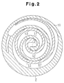
- Fig. 2 is a cross-sectional view showing a movable scroll and a fixed scroll of the compressor illustrated in Fig. 1;
- Fig. 3 is a cross-sectional view showing a mold and the scroll during molding of the scroll;
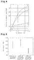
- Fig. 4 is a graph showing the mechanical characteristics of an Al-Cu alloy;
- Fig. 5 is a graph comparing the hardness of a molded product made of aluminum alloy according to the present invention, and a molded product made of AC8C prior art material; and
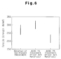
- Fig. 6 is a graph comparing the tensile strength of a molded product made of aluminum alloy according to the present invention, and a molded product made of AC8C prior art material.
-
- As shown in Fig. 1, a front housing 1 is secured to the front side (left side of drawing) of a fixed scroll 2 by bolts (not shown). A
rear housing 3 is secured to the rear side of the fixed scroll by bolts (not shown). Ashaft 4 is rotatably supported in the front housing by a main bearing 5. An eccentric pin 6 protrudes from the inner end of theshaft 4. A bushing 7 is rotatably and slidably supported by the eccentric pin 6. A bearing 8 is fit onto the bushing 7. The fixed scroll 2 has abase plate 9 and aspiral element 10 formed integrally on the inner side of theplate 9. Theouter wall 25 serves as a housing which accommodates thespiral element 10. Amovable scroll 11 is accommodated in the front housing 1. Themovable scroll 11 also has abase plate 12 and aspiral element 13 formed integrally on the inner side of theplate 12. As shown in Figs. 1 and 2, thespiral element 10 of the fixed scroll 2 is engaged with thespiral element 13 of themovable scroll 11. The end face of thespiral element 10 contacts thebase plate 12 of themovable scroll 11 while the end face of thespiral element 13 contacts thebase plate 9 of the fixed scroll 2. - A
suction chamber 16, into which refrigerant gas is drawn, is defined at the outer side of thespiral elements compression chamber 17 is defined between thespiral elements base plate 9 of the fixed scroll 2. The outlet 18 connects thecompression chamber 17 with adischarge chamber 19 defined in therear housing 3. Asuction valve 20 is provided at the outer end of the outlet 18. Astopper 21 regulates the opening of thevalve 20. - The bushing 7 is supported by the bearing 8 to allow relative rotation with a
boss 22. A knownanti-rotation mechanism 24 is provided between the front housing 1 and themovable scroll 11. Theanti-rotation mechanism 24 prohibits themovable scroll 11 from rotating about its own axis. Rotation of theshaft 4 causes the eccentric pin 6 to move themovable scroll 11 along an orbit around the center axis of theshaft 4 by way of the bushing 7 and the bearing 8. The movement of themovable scroll 11 introduces refrigerant gas into thesuction chamber 16 and then compresses the gas in thecompression chamber 17. The refrigerant gas is then discharged into thedischarge chamber 19 from the discharge outlet 18 and is finally externally discharged from adischarge port 26. - The manufacturing method of the fixed scroll 2 will now be described.
- The fixed scroll 2 is molded using a high speed die casting method. The molding conditions of the scroll 2 are shown in Table 2.
Molding Condition of Scrolls Formed By High Speed Die Casting Molding Conditions Metal Material Material used in the present embodiment (refer to Table 4) Molten Metal Temperature (°C) 700-730 Mold Temperature (°C) 150-200 Injection Speed (m/s) 1-5 Pressurizing Force (kg/cm2) 700 Cycle Time (sec.) 60 - The fixed scroll 2 is formed by first preheating
molds cavity 33 at an injection speed of 1 to 5 m/s, preferably 5 m/s. Themolds - A portion of the molded product is pressurized before the molten metal solidifies in the
cavity 33. The sectional pressurization is performed by afirst squeeze rod 35 and asecond squeeze rod 37 two seconds after the molten metal is injected into the cavity. Thefirst squeeze rod 35 is moved axially in aslide sheath 36 which forms thedischarge port 26, and thesecond squeeze rod 37 is moved axially in a section of themold 32 that corresponds to the discharge chamber (center portion of the fixed scroll 2) during pressurization of the molten metal. Thesqueeze rods squeeze rods cavity 33 where air tends to collect. That is, the portions corresponding to the corners between thespiral element 10 and the base plate 9 (indicated by the dotted line in Fig. 1). Thus, it is possible to enhance the charging ratio of the molten metal inside theentire cavity 33. After sectional pressurization and solidification of the molten metal, themolds - The fixed scroll 2 is rapidly cooled immediately after removing the scroll 2 from the
molds - The
movable scroll 11 is formed in the same manner as the fixed scroll 2. Sectional pressurization is preferably conducted only at the center portion of thebase plate 12 during molding of themovable scroll 11. Nevertheless, if desired, sectional pressurization may be conducted on two portions, as in the same manner with the fixed scroll 2, to enhance the charging ratio. - The
scrolls 2, 11 molded in the above manner are made of an aluminum alloy. The composition of this material is shown in Table 3 in comparison with the aluminum alloy used in the prior art.
- As shown in Table 3, the content ratios of each component in the present invention are as follows: copper (Cu) 4.0 to 5.0% by weight, silicon (Si) 9.0 to 12.0% by weight, magnesium (Mg) 0.5 to 1.5% by weight, iron (Fe) 0.6 to 1.0% by weight, zinc (Zn) 0.03% by weight, manganese (Mn) 0.03% by weight, and nickel (Ni) 0.03% by weight. The remainder is composed by aluminum (Al). Preferable contents of each component are as follows: Cu 4.5% by weight, Si: 10.5% by weight, Mg: 1.0% by weight, Fe: 0.83 by weight, and Zn, Mn and Ni: 0.03% by weight for each.
- Table 4 shows the mechanical characteristics of a scroll made from an alloy of the composition of Table 3.
Mechanical Characteristics of the Scroll Tensile Strength 240-300 kg/mm2 Brinell Hardness (HB) 100-120 Coefficient of Thermal Expansion 2.1 x 10⁻⁷ Heat Deformation 1.5 x 10⁻⁴% or less (180°C x 100 hrs.) - Fig. 4 shows a graph illustrating the relationship between the content of Cu and the tensile strength of the scroll when the scroll is molded from an aluminum alloy with 5% or less of Cu applied to Al. The graph also shows the same relationship with heat treatment performed on the scroll after molding and shows changes in tensile strength.
- Line a-b in Fig. 4 shows the alteration of tensile strength with respect to the Cu content ratio in a scroll on which slow cooling (annealing) is performed. In the range between a-x, solidification of Cu in Al under normal temperature produces a solid solution. Hence, the tensile strength increases as the content ratio of Cu increases.
- In the range between x-b, a compound CuAl2 is produced and thus increases the strength of the molded scroll. Since a higher content of Cu increases the amount of CuAl2, the tensile strength increases along a straight line, which inclines gently.
- Line x-c shows the tensile strength of the scroll on which quenching is performed after molding. As the content ratio of Cu increases, the tensile strength increases at a higher rate than when compared to the line x-b. This is because the higher the content ratio of Cu is, the higher the strength of the material as a solid solution becomes when quenching is performed.
- Finally, line x-d corresponds to the heat treatment performed on the
scrolls 2, 11. Artificial aging is performed on thescrolls 2, 11 by heating them at approximately 200°C for about two hours after quenching. By comparing line x-d with line x-c, it is apparent that the tensile strength becomes greater when heat treatment is conducted on the molded product. This is because a super-saturated solid solution of Cu produced in Al during quenching is stabilized by the artificial aging, which in turn increases the tensile strength of the super-saturated solid solution. - The term stabilized super-saturated solid solution refers to a state where a phase of Cu solidified in Al and a phase of CuAl2 coexists. Although the phase of CuAl2 does not deposit just by quenching, the two phases exist in the
scrolls 2,11 when artificial aging is performed. This results in the stabilization of the super-saturated solid solution and increases the tensile strength of thescrolls 2, 11. - By forming the
scrolls 2,11 in the above manner, the following effects are obtained. - Sectional pressurization during molding ensures the supply of molten metal to the portions where air pockets tend to form and improves the charging rate of the molten metal into the
cavity 33. This reduces the formation of gas bubbles in thescrolls 2, 11 after completion of molding. As a result, it is possible to employ high speed die casting, which has a short cycle time, to mold thescrolls 2, 11 while maintaining sufficient hardness and wear resistance of thescrolls 2, 11. Accordingly, a great reduction in the manufacturing cost of the compressor is possible. - After quenching is performed on the molded scrolls 2, 11, they are artificially aged. This further enhances the strength and hardness of the
scrolls 2, 11. - The composition of the aluminum alloy used to mold the
scrolls 2, 11 of the present embodiment is as shown in Table 3. Mechanical strength and hardness of the aluminum alloy, or thescrolls 2, 11, are improved by Cu. However, when the content ratio of Cu is lower than 4.0% by weight, the mechanical strength and hardness of thescrolls 2, 11 is insufficient, and when the ratio is higher than 5.0% by weight, thescrolls 2, 11 become brittle. - Flowability of the molten metal during the molding and wear resistance of the molded product are enhanced by Si. However, when the content ratio of Si is lower than 9.0% by weight, the coefficient of thermal expansion becomes large. When the content ratio of Si is higher than 12.0% by weight, the Si crystallizes as primary crystals. This lowers the machinability of the molded product. It also reduces the toughness and fatigue strength of the molded product. Furthermore, when Si exceeds 12.0% by weight, the dissolution temperature of the molten metal becomes high. Therefore, the H2 gas in the air may be absorbed in the molten metal, and oxides may be produced. Thus, there is a possibility that the molded product may become defective during molding.
- During artificial aging, Mg causes Mg2Si to be deposited. This increases the mechanical strength and hardness of the molded product. However, when the content ratio of Mg is lower than 0.5% by weight, the mechanical strength and hardness of the molded product is insufficient. When the content ratio of Mg exceeds 1.5% by weight, there is a tendency of Mg oxides being produced. This lowers the flowability of the molten metal.
- Burning and eroding of the molds caused by the molten metal during molding is prevented by Fe. When the content ratio of Fe is lower than 0.6% by weight, the effect of the Fe is insufficient. When the content ratio of Fe exceeds 1.0% by weight, Al-Fe base crystal are produced. This lowers the strength of the molded product.
- Furthermore, the aluminum alloy contains 0.03% by weight of Zn, Mn, and Ni each. This improves the strength and toughness of the
scrolls 2, 11. - The
scrolls 2, 11 are formed of the aluminum alloy containing 4.0 to 5.0% by weight of Cu, 9.0 to 12.0% by weight of Si, 0.5 to 1.5% by weight of Mg, and 0.6 to 1.0% by weight of Fe. Accordingly, it is possible to sufficiently use the characteristics of each element. - In addition, 0.01 to 0.2% by weight of Ti, which acts as a grain refining agent, is applied to the molten metal to refine the crystal grains in the aluminum alloy. Accordingly, the mechanical characteristics of the
scrolls 2, 11 are improved, formation of cracks during molding are prevented, and tensile strength is upgraded. - The temperature during artificial aging (approximately 200°C) of the
scrolls 2, 11 is higher than the temperature in the compressor during its operation (approximately 180°C, refer to Table 4). Hence, dimensional change of thescrolls 2, 11 is small. As a result, it is possible to reduce the clearance in the axial direction between thescrolls 2, 11. This reduces the amount of blow-by gas during compression and improves the compressing efficiency. - Figs. 5 and 6 are graphs comparing the hardness and the tensile strength of a molded product of the present invention and a prior art molded product. In the present invention, quenching and aging treatments are conducted on the
scrolls 2, 11 after they are molded from an alloy of the composition shown in Table 3. In the two examples of the prior art, AC8C, which is an alloy material, is used to mold scrolls. A heat treatment defined as T5 and T6 by JIS H5202 is conducted on the scrolls. In the T5 treatment, quenching is not performed on the scrolls. Only artificial aging is performed. In the T6 treatment, after quenching, aging is conducted for a few hours at a temperature between the range of 150 to 180°C. - As apparent from Figs. 5 and 6, the molded product of the present invention is superior in hardness and tensile strength when compared with a prior art molded product on which T5 treatment had been conducted and has the same hardness as the prior art molded product on which T6 had been conducted.
- Although only one embodiment of the present invention has been described herein, it should be apparent to those skilled in the art that the present invention may be embodied in many other specific forms without departing from the spirit or scope of the invention. Particularly, it should be understood that the present embodiment may be modified to the form described below.
- (1) The artificial aging may be omitted. In this case, strength, hardness, etc. is low when compared to a scroll which artificial aging has been performed on. However, it is possible to maintain the predetermined strength by performing a quenching treatment on the scroll.
- (2) A mixture of Ti and B (Ti: 0.01% by weight to 0.2% by weight, B: 0.001% by weight to 0.005% by weight) may be applied to the molten metal as a grain refining agent instead of applying only Ti. This will enable the same effects to be obtained.
-
- In addition Na (0.001% by weight to 0.01% by weight), Sr (0.01% by weight to 0.05% by weight), and Sb (0.05% by weight to 0.15% by weight) may be applied as a modification agent to modify the needle-like eutectoid silicon into a microscopic particle-like eutectoid silicon. This will enable the same effects to be obtained.
- Therefore, the described embodiment is to be considered as illustrative and not restrictive and the invention is not to be limited to the details given herein, but may be modified within the scope of the appended claims.
- Compressor scrolls are made of an aluminum alloy containing 4.0 to 5.0% by weight of Cu, 9.0 to 12.0% by weight of Si, 0.5 to 1.5% by weight of Mg, and 0.6 to 1.0% by weight of Fe. The scrolls are manufactured using a high speed die casting method.
Claims (9)
- A scroll type compressor including a fixed scroll (2) having a base plate (9) and a spiral element (10), a moveable scroll (11) having a base plate (12) and a spiral element (13), and compression chambers (17) defined between both spiral elements (10, 13), wherein a gas is compressed by moving the compression chambers (17) from the outer circumferences to the centers of the spiral elements (10, 13) according to the orbital movement of the moveable scroll (11) around the center axis of the fixed scroll (2), wherein
each of said scrolls (2, 11) is formed of an aluminum alloy containing 4.0 to 5.0 % by weight of Cu, 9.0 to 12.0 % by weight of Si, 0.5 to 1.5 % by weight of Mg, and 0.6 to 1.0 % by weight of Fe, characterized in that said aluminum alloy further contains
a modification agent including 0.01 to 0.2 % by weight of Ti, 0.03 % by weight or less of each of Zn, Mn and Ni and one of the elements 0.001 % by weight to 0.01 % by weight of Na, 0.01 % by weight to 0.05 % by weight of Sr, and 0.05 % by weight to 0.15 % by weight of Sb. - A method for producing a scroll of a scroll type compressor according to claim 1, said method being characterized by comprising the steps of:molding said scroll (2, 11) through a die casting process by using said aluminum alloy according to claim 1 andquenching the resulted scroll (2, 11).
- The method according to claim 2, wherein said molding step is performed at a temperature of about 700 to about 730 degrees Celsius, and wherein said quenching step is performed to reduce the temperature of the scroll to about 400 degrees Celsius.
- The method according to claim 2 further comprising the step of adding said modification agent to the aluminum alloy before the molten aluminum alloy is injected into a die.
- The method according to claim 2 further comprising the step of partly pressing the scroll before the molten aluminum alloy is solidified after being injected into the die.
- The method according to claim 2 further comprising the step of artificially aging the scroll after the step of quenching the scroll.
- The method according to claim 6, wherein said step of artificially aging is performed at a temperature higher than the temperature of the scroll under normal operating conditions.
- The method according to claim 7, wherein said temperature under normal operating conditions is about 180 degrees Celsius, and wherein said temperature at which the step of artificially aging is performed is about 200 degrees Celsius.
- The method according to claim 6, wherein said scroll has a Brinell hardness in the range of 100 to 120, and wherein said scroll has a tensile strength in the range of 240 to 300 kg/mm2.
Applications Claiming Priority (3)
| Application Number | Priority Date | Filing Date | Title |
|---|---|---|---|
| JP00931795A JP3684247B2 (en) | 1995-01-24 | 1995-01-24 | Scroll compressor and method for manufacturing the same |
| JP9317/95 | 1995-01-24 | ||
| JP931795 | 1995-01-24 |
Publications (2)
| Publication Number | Publication Date |
|---|---|
| EP0724077A1 EP0724077A1 (en) | 1996-07-31 |
| EP0724077B1 true EP0724077B1 (en) | 2002-11-20 |
Family
ID=11717099
Family Applications (1)
| Application Number | Title | Priority Date | Filing Date |
|---|---|---|---|
| EP96100689A Expired - Lifetime EP0724077B1 (en) | 1995-01-24 | 1996-01-18 | Scroll type compressor and method for manufacturing the same |
Country Status (5)
| Country | Link |
|---|---|
| US (1) | US5755898A (en) |
| EP (1) | EP0724077B1 (en) |
| JP (1) | JP3684247B2 (en) |
| KR (1) | KR0159845B1 (en) |
| DE (1) | DE69624853T2 (en) |
Cited By (1)
| Publication number | Priority date | Publication date | Assignee | Title |
|---|---|---|---|---|
| CN106574613A (en) * | 2014-09-11 | 2017-04-19 | 威伯科有限公司 | Air compressor made of a light metal |
Families Citing this family (11)
| Publication number | Priority date | Publication date | Assignee | Title |
|---|---|---|---|---|
| JP3764200B2 (en) * | 1996-03-19 | 2006-04-05 | 株式会社デンソー | Manufacturing method of high-strength die-cast products |
| JPH10103261A (en) * | 1996-09-27 | 1998-04-21 | Sanyo Electric Co Ltd | Scroll compressor |
| JP4590784B2 (en) | 2001-06-18 | 2010-12-01 | アイシン精機株式会社 | Sliding member and valve opening / closing timing control device |
| CN100346075C (en) * | 2004-10-21 | 2007-10-31 | 恒升精密科技股份有限公司 | Scroll processing method for compressor |
| JP4800864B2 (en) | 2006-07-03 | 2011-10-26 | 株式会社豊田中央研究所 | compressor |
| US9038704B2 (en) * | 2011-04-04 | 2015-05-26 | Emerson Climate Technologies, Inc. | Aluminum alloy compositions and methods for die-casting thereof |
| US9885347B2 (en) | 2013-10-30 | 2018-02-06 | Emerson Climate Technologies, Inc. | Components for compressors having electroless coatings on wear surfaces |
| JP6532713B2 (en) | 2015-03-12 | 2019-06-19 | 三菱重工サーマルシステムズ株式会社 | Scroll compressor |
| KR102475660B1 (en) * | 2021-06-29 | 2022-12-09 | 터보윈 주식회사 | Air compressor for hydrogen vehicle including scroll volute made of Al-Zn alloy |
| JP7795696B2 (en) * | 2022-07-22 | 2026-01-08 | サンデン株式会社 | Scroll Compressor |
| KR102822724B1 (en) * | 2024-07-24 | 2025-06-19 | 대한소결금속 주식회사 | Multi-stage Mold And Method For Manufacturing Scroll Using Multi-stage Mold |
Family Cites Families (13)
| Publication number | Priority date | Publication date | Assignee | Title |
|---|---|---|---|---|
| JPS62127447A (en) * | 1985-11-26 | 1987-06-09 | Mitsubishi Heavy Ind Ltd | Aluminum alloy for casting |
| JPH0650114B2 (en) * | 1985-11-26 | 1994-06-29 | 三菱重工業株式会社 | Scroll type fluid machinery |
| DE3817350A1 (en) * | 1987-05-23 | 1988-12-22 | Sumitomo Electric Industries | METHOD FOR PRODUCING SPIRAL-SHAPED PARTS AND METHOD FOR PRODUCING AN ALUMINUM POWDER FORGING ALLOY |
| JPS6465242A (en) * | 1987-09-04 | 1989-03-10 | Nippon Light Metal Co | Scroll made of aluminum alloy |
| JPH01273892A (en) * | 1988-04-27 | 1989-11-01 | Hitachi Ltd | scroll compressor |
| US4975243A (en) * | 1989-02-13 | 1990-12-04 | Aluminum Company Of America | Aluminum alloy suitable for pistons |
| JPH04136492A (en) * | 1990-09-28 | 1992-05-11 | Kubota Corp | Scroll for scroll compressor |
| JPH0625782A (en) * | 1991-04-12 | 1994-02-01 | Hitachi Ltd | High ductility aluminum sintered alloy and its manufacture as well as its application |
| US5169462A (en) * | 1991-12-09 | 1992-12-08 | Reynolds Metals Company | Low density aluminum alloy for engine pistons |
| JPH0650114A (en) * | 1992-07-31 | 1994-02-22 | Mitsubishi Motors Corp | Engine intake / exhaust valve |
| JPH06122933A (en) * | 1992-10-12 | 1994-05-06 | Hitachi Ltd | High ductility aluminum sintered plastic flow alloy, its manufacturing method and its use |
| US5388973A (en) * | 1994-06-06 | 1995-02-14 | Tecumseh Products Company | Variable scroll tip hardness |
| JPH0828493A (en) * | 1994-07-14 | 1996-01-30 | Furukawa Electric Co Ltd:The | Method of manufacturing aluminum alloy scroll |
-
1995
- 1995-01-24 JP JP00931795A patent/JP3684247B2/en not_active Expired - Lifetime
- 1995-11-21 KR KR1019950042375A patent/KR0159845B1/en not_active Expired - Fee Related
-
1996
- 1996-01-18 EP EP96100689A patent/EP0724077B1/en not_active Expired - Lifetime
- 1996-01-18 DE DE69624853T patent/DE69624853T2/en not_active Expired - Lifetime
- 1996-01-23 US US08/589,083 patent/US5755898A/en not_active Expired - Lifetime
Cited By (1)
| Publication number | Priority date | Publication date | Assignee | Title |
|---|---|---|---|---|
| CN106574613A (en) * | 2014-09-11 | 2017-04-19 | 威伯科有限公司 | Air compressor made of a light metal |
Also Published As
| Publication number | Publication date |
|---|---|
| JPH08200249A (en) | 1996-08-06 |
| DE69624853D1 (en) | 2003-01-02 |
| EP0724077A1 (en) | 1996-07-31 |
| DE69624853T2 (en) | 2003-04-24 |
| US5755898A (en) | 1998-05-26 |
| KR0159845B1 (en) | 1999-01-15 |
| JP3684247B2 (en) | 2005-08-17 |
| KR960029627A (en) | 1996-08-17 |
Similar Documents
| Publication | Publication Date | Title |
|---|---|---|
| EP0090253B1 (en) | Fine grained metal composition | |
| US5755898A (en) | Scroll type compressor and method for manufacturing the same | |
| EP0508426B1 (en) | Compressor equipped with a fixed scroll and a turning scroll, at least one thereof comprising a highly ductile sintered aluminum alloy, and method for production thereof | |
| EP0535593B1 (en) | Method of manufacturing sintered aluminum alloy parts | |
| EP0818548B1 (en) | Aluminum alloy impeller and manufacturing method of the same | |
| JP2761085B2 (en) | Raw material powder for Al-Si based alloy powder sintered parts and method for producing sintered parts | |
| US6079962A (en) | Composite aluminum alloy scroll machine components | |
| EP0796926B1 (en) | Production method for high strength die cast product | |
| JP2005036693A (en) | Manufacturing method of refrigerant compressor | |
| EP0533950B1 (en) | Rotor made of aluminum alloy for oil pump and method of manufacturing said rotor | |
| US5392512A (en) | Method for fabricating two-piece scroll members by diecasting | |
| JP4141207B2 (en) | High strength aluminum alloy casting and manufacturing method thereof | |
| JP2009041066A (en) | Die-cast component of magnesium superior in heat resistance, cast compressor impeller and manufacturing method therefor | |
| JP3318966B2 (en) | Manufacturing method of aluminum scroll | |
| JPH06122933A (en) | High ductility aluminum sintered plastic flow alloy, its manufacturing method and its use | |
| JP2005329459A (en) | Crystal grain fining agent for casting and its manufacturing method | |
| CN107604215B (en) | Static disc | |
| JPH08319523A (en) | Semisolid forming process for metallic material | |
| JP2832660B2 (en) | Casting method of Al-based alloy casting | |
| JPH0617993A (en) | Aluminum alloy oil pump | |
| JP2923823B2 (en) | Casting method of Al-based alloy casting | |
| KR100234758B1 (en) | Scroll for scroll compressor and manufacturing method thereof | |
| JPH08193236A (en) | High toughness wear-resistant aluminum alloy and method for producing the same | |
| JPH07314118A (en) | Cylinder block and manufacturing method thereof | |
| JPH0776701A (en) | Intermetallic compound dispersion strengthened aluminum alloy (powder) and method for producing the same |
Legal Events
| Date | Code | Title | Description |
|---|---|---|---|
| PUAI | Public reference made under article 153(3) epc to a published international application that has entered the european phase |
Free format text: ORIGINAL CODE: 0009012 |
|
| 17P | Request for examination filed |
Effective date: 19960118 |
|
| AK | Designated contracting states |
Kind code of ref document: A1 Designated state(s): DE FR GB IT |
|
| 17Q | First examination report despatched |
Effective date: 19980602 |
|
| RAP1 | Party data changed (applicant data changed or rights of an application transferred) |
Owner name: KABUSHIKI KAISHA TOYOTA JIDOSHOKKI |
|
| GRAG | Despatch of communication of intention to grant |
Free format text: ORIGINAL CODE: EPIDOS AGRA |
|
| GRAG | Despatch of communication of intention to grant |
Free format text: ORIGINAL CODE: EPIDOS AGRA |
|
| GRAH | Despatch of communication of intention to grant a patent |
Free format text: ORIGINAL CODE: EPIDOS IGRA |
|
| GRAH | Despatch of communication of intention to grant a patent |
Free format text: ORIGINAL CODE: EPIDOS IGRA |
|
| GRAA | (expected) grant |
Free format text: ORIGINAL CODE: 0009210 |
|
| AK | Designated contracting states |
Kind code of ref document: B1 Designated state(s): DE FR GB IT |
|
| REG | Reference to a national code |
Ref country code: GB Ref legal event code: FG4D |
|
| REF | Corresponds to: |
Ref document number: 69624853 Country of ref document: DE Date of ref document: 20030102 |
|
| ET | Fr: translation filed | ||
| PLBE | No opposition filed within time limit |
Free format text: ORIGINAL CODE: 0009261 |
|
| STAA | Information on the status of an ep patent application or granted ep patent |
Free format text: STATUS: NO OPPOSITION FILED WITHIN TIME LIMIT |
|
| 26N | No opposition filed |
Effective date: 20030821 |
|
| PGFP | Annual fee paid to national office [announced via postgrant information from national office to epo] |
Ref country code: FR Payment date: 20050110 Year of fee payment: 10 |
|
| PGFP | Annual fee paid to national office [announced via postgrant information from national office to epo] |
Ref country code: GB Payment date: 20050112 Year of fee payment: 10 |
|
| PG25 | Lapsed in a contracting state [announced via postgrant information from national office to epo] |
Ref country code: GB Free format text: LAPSE BECAUSE OF NON-PAYMENT OF DUE FEES Effective date: 20060118 |
|
| PG25 | Lapsed in a contracting state [announced via postgrant information from national office to epo] |
Ref country code: FR Free format text: LAPSE BECAUSE OF NON-PAYMENT OF DUE FEES Effective date: 20060131 |
|
| GBPC | Gb: european patent ceased through non-payment of renewal fee |
Effective date: 20060118 |
|
| REG | Reference to a national code |
Ref country code: FR Ref legal event code: ST Effective date: 20060929 |
|
| PGFP | Annual fee paid to national office [announced via postgrant information from national office to epo] |
Ref country code: DE Payment date: 20150113 Year of fee payment: 20 Ref country code: IT Payment date: 20150108 Year of fee payment: 20 |
|
| REG | Reference to a national code |
Ref country code: DE Ref legal event code: R071 Ref document number: 69624853 Country of ref document: DE |