EP0535593B1 - Method of manufacturing sintered aluminum alloy parts - Google Patents
Method of manufacturing sintered aluminum alloy parts Download PDFInfo
- Publication number
- EP0535593B1 EP0535593B1 EP92116643A EP92116643A EP0535593B1 EP 0535593 B1 EP0535593 B1 EP 0535593B1 EP 92116643 A EP92116643 A EP 92116643A EP 92116643 A EP92116643 A EP 92116643A EP 0535593 B1 EP0535593 B1 EP 0535593B1
- Authority
- EP
- European Patent Office
- Prior art keywords
- plasma
- aluminum alloy
- sintered aluminum
- alloy parts
- manufacturing sintered
- Prior art date
- Legal status (The legal status is an assumption and is not a legal conclusion. Google has not performed a legal analysis and makes no representation as to the accuracy of the status listed.)
- Expired - Lifetime
Links
- 229910000838 Al alloy Inorganic materials 0.000 title claims description 26
- 238000004519 manufacturing process Methods 0.000 title claims description 24
- 239000000843 powder Substances 0.000 claims description 20
- 229910045601 alloy Inorganic materials 0.000 claims description 16
- 239000000956 alloy Substances 0.000 claims description 16
- 229910052742 iron Inorganic materials 0.000 claims description 12
- 238000005245 sintering Methods 0.000 claims description 12
- 229910052726 zirconium Inorganic materials 0.000 claims description 11
- 229910052802 copper Inorganic materials 0.000 claims description 10
- 229910052748 manganese Inorganic materials 0.000 claims description 10
- 229910052684 Cerium Inorganic materials 0.000 claims description 6
- 238000005242 forging Methods 0.000 claims description 6
- 238000000748 compression moulding Methods 0.000 claims description 4
- 238000010438 heat treatment Methods 0.000 claims description 4
- 238000010273 cold forging Methods 0.000 claims description 3
- 238000001816 cooling Methods 0.000 claims description 3
- 239000012535 impurity Substances 0.000 claims 2
- 230000006835 compression Effects 0.000 claims 1
- 238000007906 compression Methods 0.000 claims 1
- 238000003825 pressing Methods 0.000 claims 1
- 238000010586 diagram Methods 0.000 description 15
- 238000000034 method Methods 0.000 description 13
- XEEYBQQBJWHFJM-UHFFFAOYSA-N Iron Chemical compound [Fe] XEEYBQQBJWHFJM-UHFFFAOYSA-N 0.000 description 11
- 238000012545 processing Methods 0.000 description 10
- 239000002245 particle Substances 0.000 description 8
- 229910018125 Al-Si Inorganic materials 0.000 description 4
- 229910018520 Al—Si Inorganic materials 0.000 description 4
- 229910021364 Al-Si alloy Inorganic materials 0.000 description 2
- OKTJSMMVPCPJKN-UHFFFAOYSA-N Carbon Chemical compound [C] OKTJSMMVPCPJKN-UHFFFAOYSA-N 0.000 description 2
- 229910001018 Cast iron Inorganic materials 0.000 description 2
- CWYNVVGOOAEACU-UHFFFAOYSA-N Fe2+ Chemical class [Fe+2] CWYNVVGOOAEACU-UHFFFAOYSA-N 0.000 description 2
- 230000008878 coupling Effects 0.000 description 2
- 238000010168 coupling process Methods 0.000 description 2
- 238000005859 coupling reaction Methods 0.000 description 2
- 229910002804 graphite Inorganic materials 0.000 description 2
- 239000010439 graphite Substances 0.000 description 2
- 238000001192 hot extrusion Methods 0.000 description 2
- 238000009434 installation Methods 0.000 description 2
- 239000007769 metal material Substances 0.000 description 2
- 230000003647 oxidation Effects 0.000 description 2
- 238000007254 oxidation reaction Methods 0.000 description 2
- 239000011863 silicon-based powder Substances 0.000 description 2
- 229910052725 zinc Inorganic materials 0.000 description 2
- 229910018084 Al-Fe Inorganic materials 0.000 description 1
- 229910018134 Al-Mg Inorganic materials 0.000 description 1
- 229910018131 Al-Mn Inorganic materials 0.000 description 1
- 229910018182 Al—Cu Inorganic materials 0.000 description 1
- 229910018192 Al—Fe Inorganic materials 0.000 description 1
- 229910018467 Al—Mg Inorganic materials 0.000 description 1
- 229910018461 Al—Mn Inorganic materials 0.000 description 1
- 229910018571 Al—Zn—Mg Inorganic materials 0.000 description 1
- 229910002796 Si–Al Inorganic materials 0.000 description 1
- 238000005299 abrasion Methods 0.000 description 1
- 238000003483 aging Methods 0.000 description 1
- XAGFODPZIPBFFR-UHFFFAOYSA-N aluminium Chemical compound [Al] XAGFODPZIPBFFR-UHFFFAOYSA-N 0.000 description 1
- FFBHFFJDDLITSX-UHFFFAOYSA-N benzyl N-[2-hydroxy-4-(3-oxomorpholin-4-yl)phenyl]carbamate Chemical compound OC1=C(NC(=O)OCC2=CC=CC=C2)C=CC(=C1)N1CCOCC1=O FFBHFFJDDLITSX-UHFFFAOYSA-N 0.000 description 1
- 238000005266 casting Methods 0.000 description 1
- 238000007796 conventional method Methods 0.000 description 1
- 230000007547 defect Effects 0.000 description 1
- 238000004512 die casting Methods 0.000 description 1
- 230000002708 enhancing effect Effects 0.000 description 1
- 238000001125 extrusion Methods 0.000 description 1
- 238000009689 gas atomisation Methods 0.000 description 1
- 230000006698 induction Effects 0.000 description 1
- 239000003562 lightweight material Substances 0.000 description 1
- 239000000463 material Substances 0.000 description 1
- 238000002844 melting Methods 0.000 description 1
- 230000008018 melting Effects 0.000 description 1
- 239000000203 mixture Substances 0.000 description 1
- 239000002994 raw material Substances 0.000 description 1
- 238000005096 rolling process Methods 0.000 description 1
- 238000007493 shaping process Methods 0.000 description 1
- 230000003313 weakening effect Effects 0.000 description 1
Images


Classifications
-
- B—PERFORMING OPERATIONS; TRANSPORTING
- B22—CASTING; POWDER METALLURGY
- B22F—WORKING METALLIC POWDER; MANUFACTURE OF ARTICLES FROM METALLIC POWDER; MAKING METALLIC POWDER; APPARATUS OR DEVICES SPECIALLY ADAPTED FOR METALLIC POWDER
- B22F3/00—Manufacture of workpieces or articles from metallic powder characterised by the manner of compacting or sintering; Apparatus specially adapted therefor ; Presses and furnaces
- B22F3/10—Sintering only
- B22F3/105—Sintering only by using electric current other than for infrared radiant energy, laser radiation or plasma ; by ultrasonic bonding
-
- C—CHEMISTRY; METALLURGY
- C22—METALLURGY; FERROUS OR NON-FERROUS ALLOYS; TREATMENT OF ALLOYS OR NON-FERROUS METALS
- C22C—ALLOYS
- C22C1/00—Making non-ferrous alloys
- C22C1/04—Making non-ferrous alloys by powder metallurgy
-
- B—PERFORMING OPERATIONS; TRANSPORTING
- B22—CASTING; POWDER METALLURGY
- B22F—WORKING METALLIC POWDER; MANUFACTURE OF ARTICLES FROM METALLIC POWDER; MAKING METALLIC POWDER; APPARATUS OR DEVICES SPECIALLY ADAPTED FOR METALLIC POWDER
- B22F3/00—Manufacture of workpieces or articles from metallic powder characterised by the manner of compacting or sintering; Apparatus specially adapted therefor ; Presses and furnaces
- B22F3/12—Both compacting and sintering
- B22F3/14—Both compacting and sintering simultaneously
-
- C—CHEMISTRY; METALLURGY
- C22—METALLURGY; FERROUS OR NON-FERROUS ALLOYS; TREATMENT OF ALLOYS OR NON-FERROUS METALS
- C22C—ALLOYS
- C22C1/00—Making non-ferrous alloys
- C22C1/04—Making non-ferrous alloys by powder metallurgy
- C22C1/0408—Light metal alloys
- C22C1/0416—Aluminium-based alloys
-
- F—MECHANICAL ENGINEERING; LIGHTING; HEATING; WEAPONS; BLASTING
- F04—POSITIVE - DISPLACEMENT MACHINES FOR LIQUIDS; PUMPS FOR LIQUIDS OR ELASTIC FLUIDS
- F04C—ROTARY-PISTON, OR OSCILLATING-PISTON, POSITIVE-DISPLACEMENT MACHINES FOR LIQUIDS; ROTARY-PISTON, OR OSCILLATING-PISTON, POSITIVE-DISPLACEMENT PUMPS
- F04C18/00—Rotary-piston pumps specially adapted for elastic fluids
- F04C18/02—Rotary-piston pumps specially adapted for elastic fluids of arcuate-engagement type, i.e. with circular translatory movement of co-operating members, each member having the same number of teeth or tooth-equivalents
- F04C18/0207—Rotary-piston pumps specially adapted for elastic fluids of arcuate-engagement type, i.e. with circular translatory movement of co-operating members, each member having the same number of teeth or tooth-equivalents both members having co-operating elements in spiral form
- F04C18/0246—Details concerning the involute wraps or their base, e.g. geometry
Definitions
- the present invention relates to a method of manufacturing sintered aluminum alloy parts using Al-Si series alloy powder as a raw material and, in particular, relates to a method of manufacturing sintered aluminum alloy parts incorporating an improved sintering method.
- ferrous series metal materials such as cast iron and sintered iron were known as the material such as for scroll shaped revolving and stationary parts in a scroll type compressor.
- non-ferrous series metal materials aluminum alloy (for example Al-Si alloy) as a light weight material was used and casting and die-casting methods were known therefor.
- JP-A-62-96603 (1987) discloses a method of manufacturing sintered Al alloy parts.
- JP-A-64-56806 (1989) discloses a manufacturing of scroll shaped parts wherein an Al alloy powder solidified via rapid cooling which is obtained by a gas atomizing method after melting an Al alloy is used, and after compression molding, in other words compacting, the Al alloy powder, the scroll shaped parts are manufactured via a hot extrusion, a hot forging after a hot extrusion or a hot forging.
- the Al-Si powder wherein Si is added to Al shows an advantage of reducing the thermal expansion coefficient of the product, however during the heating process at a high temperature the Al-Si powder is vigorously oxidized which extremely deteriorates the workability of the product so that such oxidation has to be prevented.
- US-A-4 435 213 discloses a method for producing aluminum powder alloy products having improved strength properties by compacting and shaping the alloy powder into a useful article including heating the compact rapidly by induction heating techniques, which products may be subsequently shaped by forging, extruding or rolling processes.
- Said aluminum alloy may be selected from the group consisting of (a) Al-Zn-Mg alloys containing 3-14 % Zn and 0.5-4.5 % Mg with optional contents of up to 3 % Cu, up to 3 % Fe, up to 0.5 % Si and up to 2 % Zr, (b) Al-Cu alloys containing 1-8 % Cu with optional contents of up to 5 % Mg, up to 5 % Fe, up to 2 % Si, up to 5 % Mn and up to 2 % Zr, (c) Al-Mg alloys containing 1-8 % Mg with optional contents of up to 2 % Cu, up to 3 % Fe, up to 2 % Si, up to 5 % Mn and up to 2 % Zr, (d) Al-Fe alloys containing 0.5-15 % Fe with optional contents of up to 5 % Mg, up to 10 % Cu, up to 15 % Si, up to 5 % Mn and up to 5 % Zr, (e) Al
- An object of the present invention is to provide a method of manufacturing sintered Al alloy parts of a light weight, an excellent mechanical strength and toughness having a complex shape wherein a high Si-Al alloy powder is used and a manufacturing process which produces a high density Al alloy sintered body is introduced.
- the sintered Al alloy has to have a small thermal expansion coefficient comparable to that of a cast iron which has been used long, and the thermal deformation thereof also has to be limited as small as possible.
- a reduction of thermal expansion coefficient of the product is only required, it would be enough to add, for example, Si of 1 ⁇ 45wt% to Al powder, however in order to provide a hot workability, an age hardening property, a high mechanical strength and toughness at a high temperature it is necessary to add optimum amounts of effective components such as Cu, Mn and Fe.
- the alloy when the amount of Si is less than 1wt% a sufficient mechanical strength and wear and abrasion resistance of the resultant product can not be obtained, on the other hand, when the amount of Si exceeds 45wt% the ductility thereof reduces such that the amount of Si is determined between 1-45wt% (preferably 12.2-25wt%).
- the alloy further incorporates Cu 1 - 5wt%, Fe 0.1 - 1.0wt%, Mn 0.1 - 2wt%, Mg 0.1 - 1wt%, Zr 0.5 - 5wt% and Ce 0.5 - 5wt%.
- the molded body After compression molding the Al alloy powder, the molded body is pressed by a low pressure and an electric current is conducted therethrough to cause a plasma discharge between the pressed powder particles so as to remove the oxidized films.
- the most optimum plasma discharge is generated at a plasma voltage of 2-10V and a plasma current of 1000-6500A, and the applied pressure upon the molded body is adjusted while causing discharge of the adsorbed gas on the particle surfaces.
- the plasma discharge of the present invention is carried out in the atmosphere.
- the molded body After completing the gas discharge, the molded body is further pressed to produce a sintered body in which the particles are firmly coupled.
- the pressure applied to the molded body and the total sintering time are respectively selected in the ranges 500 - 3000 N/cm 2 (50 - 300Kgf/cm 2 ) and of 5 - 20 minutes.
- the sintered alloy product manufactured according to the present invention has a high density as well as an excellent mechanical strength and toughness and the manufacturing method is suitable for manufacturing parts of light weight and small size and of a complex configuration such as a scroll shaped parts for a scroll type compressor.
- Fig.1 is a schematic diagram for explaining the manufacturing processes of a scroll shaped part of one embodiment according to the present invention.
- Fig.1 1 is a compacting process
- 2 is a compacted body
- 3 is a plasma sintering process
- 4 is a sintered body.
- Al alloy powder having a composition of Si 25wt%, Cu 3.5wt%, Mg 0.5wt%, Fe 0.5wt%, Mn 0.5wt%, Zr 1.0wt%, Ce 2.0wt% and balance Al was used, the Al alloy powder was melted and thereafter air-atomized wherein the diameter of the particles was controlled to be less than 500 ⁇ m.
- the Al alloy powder was compacted by making use of a graphite die to produce the compacted body 2, and the compacted body 2 was inserted into a graphite die having the same configuration as the scroll shaped part and pressed upto an applied pressure of 2000 N/cm 2 (200Kgf/cm 2 ) while causing a plasma discharge therein at plasma current of 5000A and plasma voltage of 5V to obtain the sintered body 4.
- the resultant sintered body was 85 mn ⁇ x 40 mn thickness in a scroll shape.
- Fig.2 is a diagram showing a relationship between plasma sinter processing time and the density ratio of the resultant body in the above process. It will be seen from the diagram that the optimum holding time is 12 minutes and when the holding time is more than 5 minutes a density ratio of 90% is obtained.
- Fig.3 is a diagram showing a relationship between applied pressure during sintering and the density ratio of the resultant body.
- the plasma current of 5000A and the plasma voltage of 5V are selected, a density ratio of more than 90% is obtained at the applied pressure of 1000 N/cm 2 (100Kgf/cm 2 ) and the optimum applied pressure under the same condition is 2000 N/m 2 (200Kgf/cm 2 ).
- Fig.4 is a diagram showing a relationship between plasma current and the density ratio of the resultant body.
- the plasma sinter processing time of 12 minutes plasma voltage of 5V and the applied pressure of 2000N/cm 2 (200Kgf/cm 2 ) are selected, the optimum plasma current is 5000A and a density ratio of more than 90% is obtained by a plasma current of more than 1500A.
- Fig.5 is a diagram showing a relationship between plasma voltage and the density ratio of the resultant body.
- the plasma current of 5000A and the applied pressure of 2000N/cm 2 (200Kgf/cm 2 ) are maintained, the optimum plasma voltage is 5V and a density ratio of more than 90% can be obtained by a plasma voltage of more than 3V.
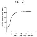
- Fig.6 is a diagram showing a relationship between plasma sinter processing time and tensile strength of the resultant body.
- the plasma current of 5000A, the plasma voltage of 5V and the applied pressure of 2000N/cm 2 (200Kgf/cm 2 ) are maintained, the tensile strength of 160N/mm 2 (16Kg/mm 2 ) is obtained at the plasma sinter processing time of 5 minutes and a sufficient tensile strength of 400N/mm 2 (40Kg/mm 2 ) is obtained at the optimum plasma sinter processing time of 12 minutes. It was confirmed based on a micro structure photograph (illustration of which is omitted) of the resultant body that the boundary surface between the powder particles was closely coupled to maintain a sufficient mechanical strength.
- Fig.7 is a schematic diagram for explaining a manufacturing process of a scroll shaped part of another embodiment according to the present invention.
- 5 shows a warm cold forging process
- 6 is a forged body.
- the other numerals indicate the same process steps and elements as in Fig.1.
- the sintered body 4 of a flat plate which was manufactured via the compacting process 1 and the plasma sintering product 3 was subjected to the warm or cold forging process 5 to produce the forged body 6 of the scroll shaped part.
- the sintered body is subjected to a plastic working to thereby disappear internal defects therein and to further enhance the mechanical strength.
- parts having complex configurations made of sintered Al-Si series alloy having light weight, excellent mechanical strength and toughness are easily obtained, and since the plasma sintering method is employed such as a vacuum installation is dispensed with, the production cost thereof is reduced because of the reduced installation cost and the production efficiency is enhanced because the molded body can be sintered in a short time.
Description
- The present invention relates to a method of manufacturing sintered aluminum alloy parts using Al-Si series alloy powder as a raw material and, in particular, relates to a method of manufacturing sintered aluminum alloy parts incorporating an improved sintering method.
- As examples of ferrous series metal materials such as cast iron and sintered iron were known as the material such as for scroll shaped revolving and stationary parts in a scroll type compressor. Further, as examples of non-ferrous series metal materials aluminum alloy (for example Al-Si alloy) as a light weight material was used and casting and die-casting methods were known therefor. Still further JP-A-62-96603 (1987) discloses a method of manufacturing sintered Al alloy parts.
- JP-A-64-56806 (1989) discloses a manufacturing of scroll shaped parts wherein an Al alloy powder solidified via rapid cooling which is obtained by a gas atomizing method after melting an Al alloy is used, and after compression molding, in other words compacting, the Al alloy powder, the scroll shaped parts are manufactured via a hot extrusion, a hot forging after a hot extrusion or a hot forging. The Al-Si powder wherein Si is added to Al shows an advantage of reducing the thermal expansion coefficient of the product, however during the heating process at a high temperature the Al-Si powder is vigorously oxidized which extremely deteriorates the workability of the product so that such oxidation has to be prevented.
- US-A-4 435 213 discloses a method for producing aluminum powder alloy products having improved strength properties by compacting and shaping the alloy powder into a useful article including heating the compact rapidly by induction heating techniques, which products may be subsequently shaped by forging, extruding or rolling processes. Said aluminum alloy may be selected from the group consisting of (a) Al-Zn-Mg alloys containing 3-14 % Zn and 0.5-4.5 % Mg with optional contents of up to 3 % Cu, up to 3 % Fe, up to 0.5 % Si and up to 2 % Zr, (b) Al-Cu alloys containing 1-8 % Cu with optional contents of up to 5 % Mg, up to 5 % Fe, up to 2 % Si, up to 5 % Mn and up to 2 % Zr, (c) Al-Mg alloys containing 1-8 % Mg with optional contents of up to 2 % Cu, up to 3 % Fe, up to 2 % Si, up to 5 % Mn and up to 2 % Zr, (d) Al-Fe alloys containing 0.5-15 % Fe with optional contents of up to 5 % Mg, up to 10 % Cu, up to 15 % Si, up to 5 % Mn and up to 5 % Zr, (e) Al-Mn alloys containing 0.5-15 % Mn with optional contents of up to 3 % Mg, upt to 3 % Cu, up to 7 % Fe, up to 10 % Si and up to 3 % Zr, and (f) Al-Si alloys containing 1-30 % Si with optional contents of up to 5 % Zn, up to 5 % Mg, up to 5 % Cu, up to 5 % Fe, up to 10 % Mn, and up to 2 % Zr, said alloys (a) - (f) containing optionally also up to 2 % Ce.
- As explained above, when parts having a complex shape such as the scroll shaped parts were manufactured such as by processings of the hot forging and the extrusion after compression molding the alloy powder obtained by adding an effective element such as Si to the powder solidified via rapid cooling of the Al alloy according to the conventional method, the working of the product was rendered difficult because of the embrittlement thereof due to the oxidation at a high temperature, therefore a long manufacturing time was required therefor, further there were problems with regard to the mechanical strength and toughness of the product, still further there was a drawback that the product thus manufactured raised the production cost.
- An object of the present invention is to provide a method of manufacturing sintered Al alloy parts of a light weight, an excellent mechanical strength and toughness having a complex shape wherein a high Si-Al alloy powder is used and a manufacturing process which produces a high density Al alloy sintered body is introduced.
- The method of manufacturing sintered aluminum alloy parts according to the present invention for solving the above problems is as claimed, in
claim 1. Advantageous further features thereof are claimed inclaims 2 to 4. - It is, for example, necessary to reduce the clearance between the scroll shaped revolving and stationary parts for enhancing the performance of a scroll type compressor. For this purpose, the sintered Al alloy has to have a small thermal expansion coefficient comparable to that of a cast iron which has been used long, and the thermal deformation thereof also has to be limited as small as possible. When a reduction of thermal expansion coefficient of the product is only required, it would be enough to add, for example, Si of 1∼45wt% to Al powder, however in order to provide a hot workability, an age hardening property, a high mechanical strength and toughness at a high temperature it is necessary to add optimum amounts of effective components such as Cu, Mn and Fe.
- Namely, in the present invention, when the amount of Si is less than 1wt% a sufficient mechanical strength and wear and abrasion resistance of the resultant product can not be obtained, on the other hand, when the amount of Si exceeds 45wt% the ductility thereof reduces such that the amount of Si is determined between 1-45wt% (preferably 12.2-25wt%). In order to increase mechanical strength of the resultant product the alloy further incorporates Cu 1 - 5wt%, Fe 0.1 - 1.0wt%, Mn 0.1 - 2wt%, Mg 0.1 - 1wt%, Zr 0.5 - 5wt% and Ce 0.5 - 5wt%.
- Further, it was found out that a reduction of mechanical strength after sintering Al alloy powder is caused by weakening the coupling force between particles because of remaining oxidized films on the surfaces of the powder particles. Accordingly, in order to increase the coupling force between particles it was found out that an addition of Ce and Zr which serves as a deoxidizing component for the alloy powder was effective, therefore these components of a proper amount are added.
- After compression molding the Al alloy powder, the molded body is pressed by a low pressure and an electric current is conducted therethrough to cause a plasma discharge between the pressed powder particles so as to remove the oxidized films. In this instance, the most optimum plasma discharge is generated at a plasma voltage of 2-10V and a plasma current of 1000-6500A, and the applied pressure upon the molded body is adjusted while causing discharge of the adsorbed gas on the particle surfaces. The plasma discharge of the present invention is carried out in the atmosphere.
- After completing the gas discharge, the molded body is further pressed to produce a sintered body in which the particles are firmly coupled. In order to obtain a sintered body having a high density, the pressure applied to the molded body and the total sintering time are respectively selected in the ranges 500 - 3000 N/cm2 (50 - 300Kgf/cm2) and of 5 - 20 minutes.
- The sintered alloy product manufactured according to the present invention has a high density as well as an excellent mechanical strength and toughness and the manufacturing method is suitable for manufacturing parts of light weight and small size and of a complex configuration such as a scroll shaped parts for a scroll type compressor.
-
- Fig.1 is a schematic diagram of manufacturing processes of a scroll shaped part of one embodiment according to the present invention ;
- Fig.2 is a diagram showing a relationship between plasma sinter processing time and the density ratio of the above embodiment ;
- Fig.3 is a diagram showing a relationship between applied pressure during sintering and the density ratio of the above embodiment ;
- Fig.4 is a diagram showing a relationship between plasma current and the density ratio of the above embodiment ;
- Fig.5 is a diagram showing a relationship between plasma voltage and the density ratio of the above embodiment ;
- Fig.6 is a diagram showing a relationship between plasma sinter processing time and tensile strength of the above embodiment ; and
- Fig.7 is a schematic diagram of manufacturing processes of a scroll shaped part of another embodiment according to the present invention.
- Hereinbelow, embodiments according to the present invention and the experimental results thereof are explained with reference to Fig.1 - Fig.7.
- Fig.1 is a schematic diagram for explaining the manufacturing processes of a scroll shaped part of one embodiment according to the present invention.
- In Fig.1, 1 is a compacting process, 2 is a compacted body, 3 is a plasma sintering process and 4 is a sintered body.
- An Al alloy powder having a composition of Si 25wt%, Cu 3.5wt%, Mg 0.5wt%, Fe 0.5wt%, Mn 0.5wt%, Zr 1.0wt%, Ce 2.0wt% and balance Al was used, the Al alloy powder was melted and thereafter air-atomized wherein the diameter of the particles was controlled to be less than 500 µm.
- At first, in the compacting process, the Al alloy powder was compacted by making use of a graphite die to produce the compacted
body 2, and the compactedbody 2 was inserted into a graphite die having the same configuration as the scroll shaped part and pressed upto an applied pressure of 2000 N/cm2 (200Kgf/cm2) while causing a plasma discharge therein at plasma current of 5000A and plasma voltage of 5V to obtain the sinteredbody 4. The resultant sintered body was 85 mnΦ x 40 mn thickness in a scroll shape. - Fig.2 is a diagram showing a relationship between plasma sinter processing time and the density ratio of the resultant body in the above process. It will be seen from the diagram that the optimum holding time is 12 minutes and when the holding time is more than 5 minutes a density ratio of 90% is obtained.
- Fig.3 is a diagram showing a relationship between applied pressure during sintering and the density ratio of the resultant body. When the plasma sinter processing time of 12 minutes, the plasma current of 5000A and the plasma voltage of 5V are selected, a density ratio of more than 90% is obtained at the applied pressure of 1000 N/cm2 (100Kgf/cm2) and the optimum applied pressure under the same condition is 2000 N/m2 (200Kgf/cm2).
- Fig.4 is a diagram showing a relationship between plasma current and the density ratio of the resultant body. When the plasma sinter processing time of 12 minutes, plasma voltage of 5V and the applied pressure of 2000N/cm2 (200Kgf/cm2) are selected, the optimum plasma current is 5000A and a density ratio of more than 90% is obtained by a plasma current of more than 1500A.
- Fig.5 is a diagram showing a relationship between plasma voltage and the density ratio of the resultant body. When the plasma sinter processing time of 12 minutes, the plasma current of 5000A and the applied pressure of 2000N/cm2 (200Kgf/cm2) are maintained, the optimum plasma voltage is 5V and a density ratio of more than 90% can be obtained by a plasma voltage of more than 3V.
- Fig.6 is a diagram showing a relationship between plasma sinter processing time and tensile strength of the resultant body. When the plasma current of 5000A, the plasma voltage of 5V and the applied pressure of 2000N/cm2 (200Kgf/cm2) are maintained, the tensile strength of 160N/mm2 (16Kg/mm2) is obtained at the plasma sinter processing time of 5 minutes and a sufficient tensile strength of 400N/mm2 (40Kg/mm2) is obtained at the optimum plasma sinter processing time of 12 minutes. It was confirmed based on a micro structure photograph (illustration of which is omitted) of the resultant body that the boundary surface between the powder particles was closely coupled to maintain a sufficient mechanical strength.
- Fig.7 is a schematic diagram for explaining a manufacturing process of a scroll shaped part of another embodiment according to the present invention. In Fig.7, 5 shows a warm cold forging process and 6 is a forged body. The other numerals indicate the same process steps and elements as in Fig.1. In the present embodiment, the
sintered body 4 of a flat plate which was manufactured via thecompacting process 1 and the plasma sinteringproduct 3 was subjected to the warm orcold forging process 5 to produce the forgedbody 6 of the scroll shaped part. Via the present method, the sintered body is subjected to a plastic working to thereby disappear internal defects therein and to further enhance the mechanical strength. - In the above embodiments, the manufacture of scroll shaped parts is explained, however the present invention is of course applicable to Al alloy sintered parts having other complex shapes.
- According to the present invention, parts having complex configurations made of sintered Al-Si series alloy having light weight, excellent mechanical strength and toughness are easily obtained, and since the plasma sintering method is employed such as a vacuum installation is dispensed with, the production cost thereof is reduced because of the reduced installation cost and the production efficiency is enhanced because the molded body can be sintered in a short time.
Claims (4)
- A method of manufacturing sintered aluminum alloy parts comprising the steps of:compression molding an Al alloy powder which consists of Si 1-45 wt%, Ce 0.5-5 wt%, Zr 0.5-5 wt%, Cu 1-5 wt%, Fe 0,1-1.0 wt%, Mn 0.1-2 wt%, Mg 0.1-1 wt% and balance Al and unavoidable impurities, and has been solidified via rapid cooling; andthereafter sintering the compression molded alloy powder by heating via an electric current conduction therethrough in a form of a plasma discharge while applying pressure thereto.
- A method of manufacturing sintered aluminum alloy parts according to claim 1, characterized in that the Al alloy powder consists of Si 25 wt%, Ce 2.0 wt%, Zr 1.0 wt %, Cu 3.5 wt%, Mg 0.5 wt%, Fe 0.5 wt%, Mn 0.5 wt% and balance Al and unavoidable impurities.
- A method of manufacturing sintered aluminum alloy parts according to claim 1, characterized by further comprising the step of
forging the sintered body via one of warm forging or cold forging to obtain a forged body of a complex configuration. - A method of manufacturing sintered aluminum alloy parts according to one of claims 1 through 3,
characterized in that the sintering conditions with the plasma discharge are a plasma voltage of 2-10 V, a plasma current of 1000-6500 A, a sintering pressure of 500-3000 N/cm2 (50-300 Kgf/cm2) and a sintering time of 5-20 minutes.
Applications Claiming Priority (2)
| Application Number | Priority Date | Filing Date | Title |
|---|---|---|---|
| JP252676/91 | 1991-10-01 | ||
| JP3252676A JPH0593205A (en) | 1991-10-01 | 1991-10-01 | Production of aluminum sintered alloy part |
Publications (2)
| Publication Number | Publication Date |
|---|---|
| EP0535593A1 EP0535593A1 (en) | 1993-04-07 |
| EP0535593B1 true EP0535593B1 (en) | 1996-07-31 |
Family
ID=17240692
Family Applications (1)
| Application Number | Title | Priority Date | Filing Date |
|---|---|---|---|
| EP92116643A Expired - Lifetime EP0535593B1 (en) | 1991-10-01 | 1992-09-29 | Method of manufacturing sintered aluminum alloy parts |
Country Status (5)
| Country | Link |
|---|---|
| US (1) | US5346667A (en) |
| EP (1) | EP0535593B1 (en) |
| JP (1) | JPH0593205A (en) |
| KR (1) | KR930008172A (en) |
| DE (1) | DE69212555T2 (en) |
Families Citing this family (21)
| Publication number | Priority date | Publication date | Assignee | Title |
|---|---|---|---|---|
| US5545487A (en) * | 1994-02-12 | 1996-08-13 | Hitachi Powdered Metals Co., Ltd. | Wear-resistant sintered aluminum alloy and method for producing the same |
| US5623727A (en) * | 1995-11-16 | 1997-04-22 | Vawter; Paul | Method for manufacturing powder metallurgical tooling |
| US5985207A (en) * | 1995-11-16 | 1999-11-16 | Vawter; Paul D. | Method for manufacturing powder metallurgical tooling |
| JPH10103261A (en) * | 1996-09-27 | 1998-04-21 | Sanyo Electric Co Ltd | Scroll compressor |
| US5760378A (en) * | 1997-04-17 | 1998-06-02 | Aerojet-General Corporation | Method of inductive bonding sintered compacts of heavy alloys |
| WO2002077308A1 (en) * | 2001-03-23 | 2002-10-03 | Sumitomo Electric Industries, Ltd. | Heat-resistant and creep-resistant aluminum alloy and billet thereof, and method for their production |
| WO2006070879A1 (en) * | 2004-12-28 | 2006-07-06 | Nippon Light Metal Company, Ltd. | Method for producing aluminum composite material |
| EP2163219B1 (en) | 2008-09-15 | 2012-04-11 | Straumann Holding AG | Cassette for storage of medical instruments |
| WO2012047868A2 (en) * | 2010-10-04 | 2012-04-12 | Gkn Sinter Metals, Llc | Aluminum powder metal alloying method |
| KR101239422B1 (en) * | 2011-02-10 | 2013-03-06 | 주식회사 풍산 | Scroll Manufacturing Method Using Warm and Cold Forging, and the Same Apparatus |
| FR2973265B1 (en) | 2011-03-31 | 2014-03-28 | Centre Nat Rech Scient | FLASH SINTER MANUFACTURING METHOD OF A COMPLEX SHAPE PIECE AND DEVICE FOR IMPLEMENTING SUCH A METHOD. |
| KR102185731B1 (en) * | 2014-04-07 | 2020-12-02 | 안요환 | Powdered Bones Jewelizing Method |
| WO2016205719A1 (en) * | 2015-06-19 | 2016-12-22 | Applied Materials, Inc. | Additive manufacturing with electrostatic compaction |
| JP6797642B2 (en) * | 2015-12-10 | 2020-12-09 | キヤノン株式会社 | Raw material powder processing method and three-dimensional model manufacturing method |
| FR3058340B1 (en) * | 2016-11-07 | 2019-01-25 | Sorbonne Universite | PULSE CURVING SINK DEVICE AND ASSOCIATED METHOD |
| CA3043233A1 (en) * | 2016-12-21 | 2018-06-28 | Arconic Inc. | Aluminum alloy products having fine eutectic-type structures, and methods for making the same |
| CN106584012B (en) * | 2016-12-30 | 2019-07-12 | 常州世竟液态金属有限公司 | A kind of amorphous alloy shaping methods |
| US11192188B2 (en) * | 2017-05-26 | 2021-12-07 | Hamilton Sundstrand Corporation | Method of manufacturing aluminum alloy articles |
| CN108356261A (en) * | 2018-04-12 | 2018-08-03 | 泰州润杰物流安全装备科技有限公司 | A kind of powder body material and preparation method for alusil alloy 3D printing |
| CN112191844A (en) * | 2020-09-03 | 2021-01-08 | 苏州耀国电子有限公司 | 3D printing method of aluminum-copper alloy |
| CN112658221B (en) * | 2020-12-04 | 2022-05-06 | 西安交通大学 | Continuous casting method of high-entropy alloy |
Family Cites Families (11)
| Publication number | Priority date | Publication date | Assignee | Title |
|---|---|---|---|---|
| AU432371B2 (en) * | 1967-07-13 | 1973-02-06 | Commonwealth Scientific And Industrial Research Organization | Plasma sintering |
| US4432296A (en) * | 1982-04-06 | 1984-02-21 | Grondin Edward A | Apparatus and method for reducing waste in tufting |
| US4435213A (en) * | 1982-09-13 | 1984-03-06 | Aluminum Company Of America | Method for producing aluminum powder alloy products having improved strength properties |
| FR2537656B1 (en) * | 1982-12-08 | 1987-12-24 | Pechiney Aluminium | PISTON INSERTS OF DIESEL ENGINES OF ALUMINUM-SILICON ALLOYS HAVING IMPROVED HOT RESISTANCE AND WORKABILITY |
| DE3481322D1 (en) * | 1983-12-02 | 1990-03-15 | Sumitomo Electric Industries | ALUMINUM ALLOYS AND METHOD FOR THEIR PRODUCTION. |
| BR8406548A (en) * | 1983-12-19 | 1985-10-15 | Sumitomo Electric Industries | ALUMINUM ALLOY REINFORCED BY DISPERSION AND RESISTANT TO HEAT AND WEAR AND PROCESS FOR ITS PRODUCTION |
| JPS6296603A (en) * | 1985-10-22 | 1987-05-06 | Honda Motor Co Ltd | Production of structural member made of heat-resistant high-strength al sintered alloy |
| NO161686C (en) * | 1986-06-20 | 1989-09-13 | Raufoss Ammunisjonsfabrikker | ALUMINUM ALLOY, PROCEDURE FOR ITS MANUFACTURING AND USE OF THE ALLOY IN ELECTRIC WIRES. |
| FR2604186A1 (en) * | 1986-09-22 | 1988-03-25 | Peugeot | PROCESS FOR MANUFACTURING HYPERSILICALLY ALUMINUM ALLOY PARTS OBTAINED FROM COOLED COOLED POWDERS AT HIGH SPEED |
| US4929415A (en) * | 1988-03-01 | 1990-05-29 | Kenji Okazaki | Method of sintering powder |
| US4933140A (en) * | 1988-11-17 | 1990-06-12 | Ceracon, Inc. | Electrical heating of graphite grain employed in consolidation of objects |
-
1991
- 1991-10-01 JP JP3252676A patent/JPH0593205A/en active Pending
-
1992
- 1992-09-23 KR KR1019920017302A patent/KR930008172A/en not_active Application Discontinuation
- 1992-09-29 US US07/953,018 patent/US5346667A/en not_active Expired - Fee Related
- 1992-09-29 DE DE69212555T patent/DE69212555T2/en not_active Expired - Fee Related
- 1992-09-29 EP EP92116643A patent/EP0535593B1/en not_active Expired - Lifetime
Also Published As
| Publication number | Publication date |
|---|---|
| DE69212555D1 (en) | 1996-09-05 |
| KR930008172A (en) | 1993-05-21 |
| DE69212555T2 (en) | 1997-02-13 |
| US5346667A (en) | 1994-09-13 |
| JPH0593205A (en) | 1993-04-16 |
| EP0535593A1 (en) | 1993-04-07 |
Similar Documents
| Publication | Publication Date | Title |
|---|---|---|
| EP0535593B1 (en) | Method of manufacturing sintered aluminum alloy parts | |
| US4702885A (en) | Aluminum alloy and method for producing the same | |
| US4135922A (en) | Metal article and powder alloy and method for producing metal article from aluminum base powder alloy containing silicon and manganese | |
| US5561829A (en) | Method of producing structural metal matrix composite products from a blend of powders | |
| JPH0480081B2 (en) | ||
| JP2761085B2 (en) | Raw material powder for Al-Si based alloy powder sintered parts and method for producing sintered parts | |
| Chen et al. | A novel method for net-shape forming of hypereutectic Al–Si alloys by thixocasting with powder preforms | |
| US5384087A (en) | Aluminum-silicon carbide composite and process for making the same | |
| JP3845035B2 (en) | Method for manufacturing piston for internal combustion engine and piston for internal combustion engine | |
| US4889557A (en) | Aluminium alloy having an excellent forgiability | |
| US20040208772A1 (en) | Sinter metal parts with homogeneous distribution of non-homogeneously melting components as method for the production thereof | |
| JPH0154421B2 (en) | ||
| KR100292119B1 (en) | Electrode material, method for manufacturing electrode material, and method for manufacturing electrode | |
| JP3368600B2 (en) | Manufacturing method of high heat resistant aluminum alloy | |
| JPH11277173A (en) | Magnesium alloy-made forged thin box body and manufacture thereof | |
| JP3355673B2 (en) | Heat-resistant aluminum alloy and method for producing the same | |
| US20040105775A1 (en) | Method of manufacturing dispersion strengthened copper and/or hyper-nucleated metal matrix composite resistance welding electrodes | |
| JP2798709B2 (en) | Manufacturing method of aluminum alloy powder sintered parts | |
| JP2535789B2 (en) | Method for producing superplastic hypereutectic aluminum-silicon powder metallurgy alloy | |
| JP2917999B2 (en) | Method for producing high-strength aluminum alloy compact | |
| JPH06228697A (en) | Rapidly solidified al alloy excellent in high temperature property | |
| JP2003096524A (en) | Aluminum alloy, piston made of aluminum alloy, and method of producing piston made of aluminum alloy | |
| JPH1177214A (en) | Magnesium alloy forged thin-walled parts, and its manufacture | |
| JPH07278714A (en) | Aluminum powder alloy and its production | |
| JP2584488B2 (en) | Processing method of wear resistant aluminum alloy |
Legal Events
| Date | Code | Title | Description |
|---|---|---|---|
| PUAI | Public reference made under article 153(3) epc to a published international application that has entered the european phase |
Free format text: ORIGINAL CODE: 0009012 |
|
| AK | Designated contracting states |
Kind code of ref document: A1 Designated state(s): DE FR GB |
|
| 17P | Request for examination filed |
Effective date: 19930415 |
|
| 17Q | First examination report despatched |
Effective date: 19950119 |
|
| GRAH | Despatch of communication of intention to grant a patent |
Free format text: ORIGINAL CODE: EPIDOS IGRA |
|
| GRAH | Despatch of communication of intention to grant a patent |
Free format text: ORIGINAL CODE: EPIDOS IGRA |
|
| GRAA | (expected) grant |
Free format text: ORIGINAL CODE: 0009210 |
|
| AK | Designated contracting states |
Kind code of ref document: B1 Designated state(s): DE FR GB |
|
| REF | Corresponds to: |
Ref document number: 69212555 Country of ref document: DE Date of ref document: 19960905 |
|
| ET | Fr: translation filed |
Free format text: CORRECTIONS |
|
| PLBE | No opposition filed within time limit |
Free format text: ORIGINAL CODE: 0009261 |
|
| STAA | Information on the status of an ep patent application or granted ep patent |
Free format text: STATUS: NO OPPOSITION FILED WITHIN TIME LIMIT |
|
| 26N | No opposition filed | ||
| REG | Reference to a national code |
Ref country code: GB Ref legal event code: 746 Effective date: 19970704 |
|
| PGFP | Annual fee paid to national office [announced via postgrant information from national office to epo] |
Ref country code: GB Payment date: 20010919 Year of fee payment: 10 |
|
| REG | Reference to a national code |
Ref country code: GB Ref legal event code: IF02 |
|
| PGFP | Annual fee paid to national office [announced via postgrant information from national office to epo] |
Ref country code: FR Payment date: 20020730 Year of fee payment: 11 |
|
| PG25 | Lapsed in a contracting state [announced via postgrant information from national office to epo] |
Ref country code: GB Free format text: LAPSE BECAUSE OF NON-PAYMENT OF DUE FEES Effective date: 20020929 |
|
| PGFP | Annual fee paid to national office [announced via postgrant information from national office to epo] |
Ref country code: DE Payment date: 20021129 Year of fee payment: 11 |
|
| GBPC | Gb: european patent ceased through non-payment of renewal fee |
Effective date: 20020929 |
|
| PG25 | Lapsed in a contracting state [announced via postgrant information from national office to epo] |
Ref country code: DE Free format text: LAPSE BECAUSE OF NON-PAYMENT OF DUE FEES Effective date: 20040401 |
|
| PG25 | Lapsed in a contracting state [announced via postgrant information from national office to epo] |
Ref country code: FR Free format text: LAPSE BECAUSE OF NON-PAYMENT OF DUE FEES Effective date: 20040528 |
|
| REG | Reference to a national code |
Ref country code: FR Ref legal event code: ST |