JP6532713B2 - Scroll compressor - Google Patents
Scroll compressor Download PDFInfo
- Publication number
- JP6532713B2 JP6532713B2 JP2015049877A JP2015049877A JP6532713B2 JP 6532713 B2 JP6532713 B2 JP 6532713B2 JP 2015049877 A JP2015049877 A JP 2015049877A JP 2015049877 A JP2015049877 A JP 2015049877A JP 6532713 B2 JP6532713 B2 JP 6532713B2
- Authority
- JP
- Japan
- Prior art keywords
- scroll
- end plate
- wall
- scrolls
- height
- Prior art date
- Legal status (The legal status is an assumption and is not a legal conclusion. Google has not performed a legal analysis and makes no representation as to the accuracy of the status listed.)
- Active
Links
Images


Classifications
-
- F—MECHANICAL ENGINEERING; LIGHTING; HEATING; WEAPONS; BLASTING
- F04—POSITIVE - DISPLACEMENT MACHINES FOR LIQUIDS; PUMPS FOR LIQUIDS OR ELASTIC FLUIDS
- F04C—ROTARY-PISTON, OR OSCILLATING-PISTON, POSITIVE-DISPLACEMENT MACHINES FOR LIQUIDS; ROTARY-PISTON, OR OSCILLATING-PISTON, POSITIVE-DISPLACEMENT PUMPS
- F04C18/00—Rotary-piston pumps specially adapted for elastic fluids
- F04C18/02—Rotary-piston pumps specially adapted for elastic fluids of arcuate-engagement type, i.e. with circular translatory movement of co-operating members, each member having the same number of teeth or tooth-equivalents
- F04C18/0207—Rotary-piston pumps specially adapted for elastic fluids of arcuate-engagement type, i.e. with circular translatory movement of co-operating members, each member having the same number of teeth or tooth-equivalents both members having co-operating elements in spiral form
- F04C18/0246—Details concerning the involute wraps or their base, e.g. geometry
-
- F—MECHANICAL ENGINEERING; LIGHTING; HEATING; WEAPONS; BLASTING
- F04—POSITIVE - DISPLACEMENT MACHINES FOR LIQUIDS; PUMPS FOR LIQUIDS OR ELASTIC FLUIDS
- F04C—ROTARY-PISTON, OR OSCILLATING-PISTON, POSITIVE-DISPLACEMENT MACHINES FOR LIQUIDS; ROTARY-PISTON, OR OSCILLATING-PISTON, POSITIVE-DISPLACEMENT PUMPS
- F04C18/00—Rotary-piston pumps specially adapted for elastic fluids
- F04C18/02—Rotary-piston pumps specially adapted for elastic fluids of arcuate-engagement type, i.e. with circular translatory movement of co-operating members, each member having the same number of teeth or tooth-equivalents
- F04C18/0207—Rotary-piston pumps specially adapted for elastic fluids of arcuate-engagement type, i.e. with circular translatory movement of co-operating members, each member having the same number of teeth or tooth-equivalents both members having co-operating elements in spiral form
- F04C18/0215—Rotary-piston pumps specially adapted for elastic fluids of arcuate-engagement type, i.e. with circular translatory movement of co-operating members, each member having the same number of teeth or tooth-equivalents both members having co-operating elements in spiral form where only one member is moving
-
- F—MECHANICAL ENGINEERING; LIGHTING; HEATING; WEAPONS; BLASTING
- F04—POSITIVE - DISPLACEMENT MACHINES FOR LIQUIDS; PUMPS FOR LIQUIDS OR ELASTIC FLUIDS
- F04C—ROTARY-PISTON, OR OSCILLATING-PISTON, POSITIVE-DISPLACEMENT MACHINES FOR LIQUIDS; ROTARY-PISTON, OR OSCILLATING-PISTON, POSITIVE-DISPLACEMENT PUMPS
- F04C18/00—Rotary-piston pumps specially adapted for elastic fluids
- F04C18/02—Rotary-piston pumps specially adapted for elastic fluids of arcuate-engagement type, i.e. with circular translatory movement of co-operating members, each member having the same number of teeth or tooth-equivalents
- F04C18/0207—Rotary-piston pumps specially adapted for elastic fluids of arcuate-engagement type, i.e. with circular translatory movement of co-operating members, each member having the same number of teeth or tooth-equivalents both members having co-operating elements in spiral form
- F04C18/0246—Details concerning the involute wraps or their base, e.g. geometry
- F04C18/0269—Details concerning the involute wraps
- F04C18/0276—Different wall heights
-
- F—MECHANICAL ENGINEERING; LIGHTING; HEATING; WEAPONS; BLASTING
- F04—POSITIVE - DISPLACEMENT MACHINES FOR LIQUIDS; PUMPS FOR LIQUIDS OR ELASTIC FLUIDS
- F04C—ROTARY-PISTON, OR OSCILLATING-PISTON, POSITIVE-DISPLACEMENT MACHINES FOR LIQUIDS; ROTARY-PISTON, OR OSCILLATING-PISTON, POSITIVE-DISPLACEMENT PUMPS
- F04C2230/00—Manufacture
- F04C2230/40—Heat treatment
- F04C2230/41—Hardening; Annealing
-
- F—MECHANICAL ENGINEERING; LIGHTING; HEATING; WEAPONS; BLASTING
- F04—POSITIVE - DISPLACEMENT MACHINES FOR LIQUIDS; PUMPS FOR LIQUIDS OR ELASTIC FLUIDS
- F04C—ROTARY-PISTON, OR OSCILLATING-PISTON, POSITIVE-DISPLACEMENT MACHINES FOR LIQUIDS; ROTARY-PISTON, OR OSCILLATING-PISTON, POSITIVE-DISPLACEMENT PUMPS
- F04C2230/00—Manufacture
- F04C2230/90—Improving properties of machine parts
- F04C2230/92—Surface treatment
-
- F—MECHANICAL ENGINEERING; LIGHTING; HEATING; WEAPONS; BLASTING
- F04—POSITIVE - DISPLACEMENT MACHINES FOR LIQUIDS; PUMPS FOR LIQUIDS OR ELASTIC FLUIDS
- F04C—ROTARY-PISTON, OR OSCILLATING-PISTON, POSITIVE-DISPLACEMENT MACHINES FOR LIQUIDS; ROTARY-PISTON, OR OSCILLATING-PISTON, POSITIVE-DISPLACEMENT PUMPS
- F04C2270/00—Control; Monitoring or safety arrangements
- F04C2270/16—Wear
-
- F—MECHANICAL ENGINEERING; LIGHTING; HEATING; WEAPONS; BLASTING
- F04—POSITIVE - DISPLACEMENT MACHINES FOR LIQUIDS; PUMPS FOR LIQUIDS OR ELASTIC FLUIDS
- F04C—ROTARY-PISTON, OR OSCILLATING-PISTON, POSITIVE-DISPLACEMENT MACHINES FOR LIQUIDS; ROTARY-PISTON, OR OSCILLATING-PISTON, POSITIVE-DISPLACEMENT PUMPS
- F04C29/00—Component parts, details or accessories of pumps or pumping installations, not provided for in groups F04C18/00 - F04C28/00
- F04C29/12—Arrangements for admission or discharge of the working fluid, e.g. constructional features of the inlet or outlet
Landscapes
- Engineering & Computer Science (AREA)
- Mechanical Engineering (AREA)
- General Engineering & Computer Science (AREA)
- Rotary Pumps (AREA)
- Applications Or Details Of Rotary Compressors (AREA)
Description
本発明は、三次元圧縮タイプのスクロール圧縮機に関するものである。 The present invention relates to a three-dimensional compression type scroll compressor.
スクロール圧縮機は、端板上に渦巻状ラップを立設した一対の固定スクロールおよび旋回スクロールを備え、その一対の固定スクロールおよび旋回スクロールの渦巻状ラップ(渦巻状壁体)同士を互いに対向させ、180°位相をずらして噛み合わせることにより、両スクロール間に密閉された圧縮室を形成し、流体を圧縮する構成とされている。かかるスクロール圧縮機において、固定スクロールおよび旋回スクロールの渦巻状ラップのラップ高さを渦巻き方向の全周において一様な高さとし、圧縮室を外周側から内周側に容積を縮小しながら移動させ、圧縮室に吸入された流体を渦巻状ラップの周方向に圧縮する二次元圧縮構造としたものが一般的である。 The scroll compressor includes a pair of fixed scrolls and orbiting scrolls in which spiral wraps are erected on an end plate, and the spiral wraps (spiral wall bodies) of the pair of fixed scrolls and orbiting scrolls face each other, By engaging 180 degrees out of phase, a closed compression chamber is formed between the scrolls to compress the fluid. In such a scroll compressor, the wrap heights of the fixed scroll and the spiral wrap of the orbiting scroll are made uniform along the entire circumference in the spiral direction, and the compression chamber is moved while reducing the volume from the outer peripheral side to the inner peripheral side, Generally, a two-dimensional compression structure is used in which the fluid drawn into the compression chamber is compressed in the circumferential direction of the spiral wrap.
一方、スクロール圧縮機を高効率化、小型軽量化するため、固定スクロールおよび旋回スクロールの渦巻状ラップの歯先面および歯底面の渦巻き方向に沿う所定位置に各々段差部を設け、その段差部を境に渦巻状ラップの外周側のラップ高さを内周側のラップ高さよりも高くし、圧縮室の軸線方向高さを渦巻状ラップの外周側において内周側の高さよりも高くすることにより、流体を渦巻状ラップの周方向および高さ方向の双方に圧縮する構造とした三次元圧縮タイプのスクロール圧縮機が提供されている。 On the other hand, in order to increase the efficiency and size and weight of the scroll compressor, step portions are provided at predetermined positions along the spiral direction of the tip and bottom surfaces of the fixed scroll and spiral scroll of the orbiting scroll, By making the wrap height on the outer circumference side of the spiral wrap higher than the wrap height on the inner circumference side at the boundary and making the axial height of the compression chamber higher than the height on the outer circumference side of the spiral wrap There is provided a three-dimensional compression type scroll compressor configured to compress fluid in both the circumferential direction and height direction of the spiral wrap.
このような三次元圧縮タイプのスクロール圧縮機として、例えば特許文献1に示されるように、固定スクロールおよび旋回スクロールの両方の端板に端板側段差部が形成され、かつ固定スクロールおよび旋回スクロールの両方の渦巻状ラップに端板側段差部に対応したラップ側段差部が形成されたものが知られている。 As such a three-dimensional compression type scroll compressor, as shown in, for example, Patent Document 1, an end plate side step portion is formed on both end plates of fixed scroll and orbiting scroll, and fixed scroll and orbiting scroll It is known that wrap side step parts corresponding to the end plate side step parts are formed on both spiral wraps.
また、特許文献2に示されるように、固定スクロールと旋回スクロールのうちのいずれか一方のスクロールの端板に端板側段差部が設けられ、他方のスクロールの渦巻状ラップに端板側段差部に対応したラップ側段差部が設けられたものが知られている。
In addition, as disclosed in
一方、一般に、各スクロールの渦巻状ラップ同士の接触による摩耗や焼き付きを防止するため、一方のスクロール又は両方のスクロールに対して、コーティング等の表面硬化処理が施される。例えば、特許文献3には、三次元圧縮タイプのスクロール圧縮機の段差部にコーティングすることが開示されている。 On the other hand, in general, in order to prevent wear and seizing due to contact between the spiral wraps of the scrolls, surface hardening treatment such as coating is applied to one or both of the scrolls. For example, Patent Document 3 discloses coating a stepped portion of a three-dimensional compression type scroll compressor.
特許文献1のように、固定スクロール及び旋回スクロールの両方に段差部が設けられ、これらの段差部の高さが等しい場合には、両スクロールは同一形状となる。したがって、固定スクロールや旋回スクロールのどちらに表面硬化処理を施しても、その効果についての相違はない。
しかし、本発明者等が鋭意検討したところ、固定スクロール及び旋回スクロールの段差部の高さが異なる場合には、それぞれのスクロールの形状が異なるので、いずれか一方のスクロールに表面硬化処理を施すとしても、あるいはいずれか一方のスクロールに他方よりも硬い表面硬化処理を施すとしても、いずれのスクロールを選択するのかによって期待できる効果が異なるという課題を見出した。すなわち、端板側段差部とラップ側段差部との接触を考慮した場合、これら段差部の高さの違いに応じて、適切な表面硬化処理が存在することを見出した。
As in Patent Document 1, when the stepped portions are provided on both the fixed scroll and the orbiting scroll, and the heights of the stepped portions are equal, both the scrolls have the same shape. Therefore, there is no difference in the effect of surface hardening on either the fixed scroll or the orbiting scroll.
However, when the inventors of the present invention and others carefully studied, when the heights of the step portions of the fixed scroll and the orbiting scroll are different, the shapes of the respective scrolls are different. Also, even if surface hardening treatment harder than the other is applied to one of the scrolls, it has been found that the expected effect is different depending on which scroll is selected. That is, when the contact between the end plate side stepped portion and the lap side stepped portion is taken into consideration, it has been found that an appropriate surface hardening treatment exists depending on the difference in height of the stepped portions.
同様に、特許文献2のように、固定スクロールと旋回スクロールのうちのいずれか一方のスクロールの端板に端板側段差部が設けられ、他方のスクロールの渦巻状ラップに端板側段差部に対応したラップ側段差部が設けられた場合も、それぞれのスクロールの形状が異なるので、上記と同様の課題が生じる。
Similarly, as in
本発明は、このような事情に鑑みてなされたものであって、スクロールに適切な表面硬化処理を施すことによって摩耗を低減することができるスクロール圧縮機を提供することを目的とする。 The present invention has been made in view of such circumstances, and it is an object of the present invention to provide a scroll compressor capable of reducing wear by performing appropriate surface hardening treatment on a scroll.
上記解題を解決するために、本発明のスクロール圧縮機は以下の手段を採用する。
すなわち、本発明にかかるスクロール圧縮機は、端板の一側面に立設された渦巻状の壁体を有する固定スクロールと、端板の一側面に立設された渦巻状の壁体を有し、前記各壁体どうしを噛み合わせて自転を阻止されつつ公転旋回運動可能に支持された旋回スクロールと、両前記スクロールによって圧縮された流体が吐出される吐出ポートとを備え、両前記スクロールのいずれか一方の端板には、前記一側面に、高さが壁体の渦に沿ってその中心部側で高く外終端側で低くなるように形成された端板側段差部が設けられ、両前記スクロールの他方の壁体には、前記端板側段差部に対応し、高さが渦の中心部側で低く外終端側で高くなるように形成された壁体側段差部が設けられたスクロール圧縮機において、前記端板側段差部が設けられた一方の前記スクロールには、表面硬化処理が施されており、他方の前記スクロールには、表面硬化処理が施されていないことを特徴とする。
In order to solve the above problem, the scroll compressor of the present invention adopts the following means.
That is, the scroll compressor according to the present invention has a fixed scroll having a spiral wall standing on one side of an end plate and a spiral wall standing on one side of the end plate. A rotating scroll supported so as to be able to revolve and move while preventing the rotation by meshing the walls with each other, and a discharge port from which fluid compressed by the scrolls is discharged, any of the scrolls The one end plate is provided with an end plate side step portion formed on the one side surface so that the height is high along the center of the wall along the vortex of the wall and lower on the outer end side, The other wall of the scroll is provided with a wall-side stepped portion corresponding to the end plate-side stepped portion and having a height which is low on the center side of the vortex and high on the outer end side in the compressor, one of pre-Symbol end plate side step portion is provided The of the scroll, and the surface hardening treatment is applied to the other of the scroll, characterized in that no surface hardening treatment is performed.
固定スクロールと旋回スクロールのうちのいずれか一方のスクロールに端板側段差部が設けられ、他方のスクロールに壁体側段差部がある場合、固定スクロールと旋回スクロールの形状は非対称となり、同一の形状とならない。固定スクロールと旋回スクロールとが噛み合って公転旋回運動を行うと、端板側段差部に対して壁体側段差部が接触しながら相対的に移動する。この場合、端板側段差部の方が接触面積が大きくなるので、端板側段差部に表面硬化処理を施すことによって表面硬化処理の減耗を可及的に防止し、焼き付きを回避することができる。また、壁体側段差部が設けられた壁体は、壁体側段差部の根本に応力集中が生じる。一方、表面硬化処理は表面の面粗度を悪化させるので壁体側段差部の根本の疲労強度をさらに低下させてしまうおそれがある。そこで、壁体側段差部が設けられたスクロールには表面硬化処理を施さないこととした。
表面硬化処理としては、例えば、固定スクロール及び旋回スクロールがアルミ合金製とされている場合には、硬質アルマイト処理が用いられる。また、固定スクロール及び旋回スクロールが鋳鉄又は鉄の場合には、リン酸塩皮膜やDLC(Diamond Like Carbon)が用いられる。
例えば、旋回スクロールに端板側段差部があり、固定スクロールに壁体側段差部がある場合には、旋回スクロールに表面硬化処理を施し、固定スクロールに表面硬化処理を施さない。
If one of the fixed scroll and the orbiting scroll is provided with the end plate side step portion and the other scroll has the wall side step portion, the shapes of the fixed scroll and the orbiting scroll become asymmetric, and the same shape It does not. When the fixed scroll and the orbiting scroll are engaged with each other to perform the orbiting motion, the wall-side step moves relative to the end-plate-side step while contacting the end plate-side step. In this case, since the contact area is larger at the end plate side step portion, it is possible to prevent wear of the surface hardening treatment as much as possible by giving surface hardening treatment to the end plate side step portion and to avoid sticking. it can. Further, in the wall provided with the wall-side stepped portion, stress concentration occurs at the root of the wall-side stepped portion. On the other hand, since the surface hardening treatment deteriorates the surface roughness of the surface, there is a possibility that the fatigue strength at the root of the step portion on the wall side may be further reduced. Therefore, the surface hardening process is not performed on the scroll provided with the wall-side stepped portion.
As the surface hardening treatment, for example, when the fixed scroll and the orbiting scroll are made of aluminum alloy, hard alumite treatment is used. In the case where the fixed scroll and the orbiting scroll are cast iron or iron, a phosphate film or DLC (Diamond Like Carbon) is used.
For example, when there is an end plate side stepped portion in the orbiting scroll and the wall side stepped portion in the fixed scroll, the surface hardening process is performed on the orbiting scroll and the surface hardening process is not performed on the fixed scroll.
また、本発明にかかるスクロール圧縮機は、端板の一側面に立設された渦巻状の壁体を有する固定スクロールと、端板の一側面に立設された渦巻状の壁体を有し、前記各壁体どうしを噛み合わせて自転を阻止されつつ公転旋回運動可能に支持された旋回スクロールと、両前記スクロールによって圧縮された流体が吐出される吐出ポートとを備え、両前記スクロールのそれぞれの端板には、前記一側面に、高さが壁体の渦に沿ってその中心部側で高く外終端側で低くなるよう形成された端板側段差部が設けられ、両前記スクロールのそれぞれの壁体には、前記端板側段差部に対応し、高さが渦の中心部側で低く外終端側で高くなるように形成された壁体側段差部が設けられ、一方の前記スクロールの前記端板側段差部と他方の前記スクロールの前記端板側段差部の高さが異なるスクロール圧縮機において、前記端板側段差部の高さが大きい一方の前記スクロールには、表面硬化処理が施されており、他方の前記スクロールには、表面硬化処理が施されていないことを特徴とする。 Further, the scroll compressor according to the present invention has a fixed scroll having a spiral wall set up on one side of an end plate, and a spiral wall set up on one side of the end plate. A rotating scroll supported so as to be able to revolve and move while preventing the rotation by meshing the walls with each other; and a discharge port from which fluid compressed by the scrolls is discharged, each of the scrolls The end plate is provided with an end plate-side stepped portion formed on the one side so that the height is high along the center of the wall along the vortex of the wall and lower on the outer end side, Each wall is provided with a wall-side stepped portion corresponding to the end plate-side stepped portion and formed such that the height is low on the center side of the vortex and high on the outer end side, and one of the scrolls Between the end plate side step portion of the In serial end plate side step portion different heights scroll compressor, the prior SL end plate side the scroll one height is large stepped portion, the surface hardening treatment has been applied to the other of the scroll And surface hardening treatment is not applied.
固定スクロールおよび旋回スクロールの両方に端板側段差部が形成され、かつ固定スクロールおよび旋回スクロールの壁体に端板側段差部に対応した壁体側段差部が形成され、さらに対応する端板側段差部と壁体側段差部の高さが異なる場合、固定スクロールと旋回スクロールの形状は非対称となり、同一の形状とならない。固定スクロールと旋回スクロールとが噛み合って公転旋回運動を行うと、端板側段差部に対して壁体側段差部が接触しながら相対的に移動する。この場合、端板側段差部の方が接触面積が大きくなるので、端板側段差部の高さが大きい方のスクロールに表面硬化処理を施すことによって表面処理の減耗を可及的に防止し、焼き付きを回避することができる。また、壁体側段差部が設けられた壁体は、壁体側段差部の根本に応力集中が生じる。一方、表面硬化処理は表面の面粗度を悪化させるので壁体側段差部の根本の疲労強度をさらに低下させてしまうおそれがある。そこで、壁体側段差部の高さが大きい方のスクロールには表面硬化処理を施さないこととした。
表面硬化処理としては、例えば、固定スクロール及び旋回スクロールがアルミ合金製とされている場合には、硬質アルマイト処理が用いられる。
例えば、旋回スクロールの端板側段差部の方が固定スクロールの壁体側段差部よりも高さが大きい場合には、旋回スクロールに表面硬化処理を施し、固定スクロールに表面硬化処理を施さない。
An end plate side step portion is formed on both the fixed scroll and the orbiting scroll, and a wall side step portion corresponding to the end plate side step portion is formed on the wall of the fixed scroll and the orbiting scroll, and the corresponding end plate side step When the heights of the portion and the wall-side stepped portion are different, the shapes of the fixed scroll and the orbiting scroll become asymmetric and do not have the same shape. When the fixed scroll and the orbiting scroll are engaged with each other to perform the orbiting motion, the wall-side step moves relative to the end-plate-side step while contacting the end plate-side step. In this case, since the contact area is larger at the end plate side step portion, surface hardening treatment is applied to the scroll having the larger end plate side step portion to prevent wear of the surface treatment as much as possible. You can avoid burn-in. Further, in the wall provided with the wall-side stepped portion, stress concentration occurs at the root of the wall-side stepped portion. On the other hand, since the surface hardening treatment deteriorates the surface roughness of the surface, there is a possibility that the fatigue strength at the root of the step portion on the wall side may be further reduced. Therefore, the surface hardening process is not performed on the scroll having the larger height of the wall-side stepped portion.
As the surface hardening treatment, for example, when the fixed scroll and the orbiting scroll are made of aluminum alloy, hard alumite treatment is used.
For example, when the end plate side step portion of the orbiting scroll is larger in height than the wall side step portion of the fixed scroll, the surface hardening process is performed on the orbiting scroll, and the surface hardening process is not performed on the stationary scroll.
また、本発明にかかるスクロール圧縮機は、端板の一側面に立設された渦巻状の壁体を有する固定スクロールと、端板の一側面に立設された渦巻状の壁体を有し、前記各壁体どうしを噛み合わせて自転を阻止されつつ公転旋回運動可能に支持された旋回スクロールと、両前記スクロールによって圧縮された流体が吐出される吐出ポートとを備え、両前記スクロールのいずれか一方の端板には、前記一側面に、高さが壁体の渦に沿ってその中心部側で高く外終端側で低くなるよう形成された端板側段差部が設けられ、両前記スクロールの他方の壁体には、前記端板側段差部に対応し、高さが渦の中心部側で低く外終端側で高くなるように形成された壁体側段差部が設けられたスクロール圧縮機において、前記端板側段差部が設けられた一方の前記スクロールには、他方の前記スクロールに施された表面硬化処理よりも硬い表面硬化処理が施されていることを特徴とする。 Further, the scroll compressor according to the present invention has a fixed scroll having a spiral wall set up on one side of an end plate, and a spiral wall set up on one side of the end plate. A rotating scroll supported so as to be able to revolve and move while preventing the rotation by meshing the walls with each other, and a discharge port from which fluid compressed by the scrolls is discharged, any of the scrolls An end plate side stepped portion is formed on one side of the one end plate so that the height is high along the center of the wall along the vortex of the wall and lower on the outer end side, Scroll compression provided with a wall-side stepped portion formed on the other wall of the scroll so as to correspond to the end plate-side stepped portion and formed so that the height is low on the center side of the vortex and high on the outer end side Machine in which the end plate side stepped portion is provided The scroll, characterized in that the hard surface hardening treatment than the surface hardening treatment applied to the other of the scroll is applied.
固定スクロールと旋回スクロールのうちのいずれか一方のスクロールに端板側段差部が設けられ、他方のスクロールに壁体側段差部がある場合、固定スクロールと旋回スクロールの形状は非対称となり、同一の形状とならない。固定スクロールと旋回スクロールとが噛み合って公転旋回運動を行うと、端板側段差部に対して壁体側段差部が接触しながら相対的に移動する。この場合、端板側段差部の方が接触面積が大きくなるので、端板側段差部を有するスクロールに他方のスクロールよりも硬い表面硬化処理を施すことによって表面硬化処理の減耗を可及的に防止、焼き付きを回避することができる。
表面硬化処理としては、例えば、固定スクロール及び旋回スクロールがアルミ合金製とされている場合には、硬い方の表面処理としてNi−P(ニッケル−リン)メッキが用いられ、他方にはSn(スズ)メッキが用いられる。
例えば、旋回スクロールに端板側段差部があり、固定スクロールに壁体側段差部がある場合には、旋回スクロールに固定スクロールよりも硬い表面硬化処理を施す。
If one of the fixed scroll and the orbiting scroll is provided with the end plate side step portion and the other scroll has the wall side step portion, the shapes of the fixed scroll and the orbiting scroll become asymmetric, and the same shape It does not. When the fixed scroll and the orbiting scroll are engaged with each other to perform the orbiting motion, the wall-side step moves relative to the end-plate-side step while contacting the end plate-side step. In this case, since the contact area is larger at the end plate side step portion, by performing surface hardening treatment harder than the other scroll on the scroll having the end plate side step portion, wear of the surface hardening treatment can be minimized. It is possible to prevent and prevent burn-in.
As the surface hardening process, for example, when the fixed scroll and the orbiting scroll are made of an aluminum alloy, Ni-P (nickel-phosphorus) plating is used as the surface treatment for the harder side, and the other is Sn (tin ) Plating is used.
For example, in the case where there is an end plate side step portion in the orbiting scroll and the wall side step portion in the fixed scroll, the orbiting scroll is subjected to surface hardening processing harder than the fixed scroll.
また、本発明にかかるスクロール圧縮機は、端板の一側面に立設された渦巻状の壁体を有する固定スクロールと、端板の一側面に立設された渦巻状の壁体を有し、前記各壁体どうしを噛み合わせて自転を阻止されつつ公転旋回運動可能に支持された旋回スクロールと、両前記スクロールによって圧縮された流体が吐出される吐出ポートとを備え、両前記スクロールのそれぞれの端板には、前記一側面に、高さが壁体の渦に沿ってその中心部側で高く外終端側で低くなるよう形成された端板側段差部が設けられ、両前記スクロールのそれぞれの壁体には、前記端板側段差部に対応し、高さが渦の中心部側で低く外終端側で高くなるように形成された壁体側段差部が設けられ、一方の前記スクロールの前記端板側段差部と他方の前記スクロールの前記端板側段差部の高さが異なるスクロール圧縮機において、前記端板側段差部の高さが大きい一方の前記スクロールには、他方の前記スクロールよりも硬い表面硬化処理が施されていることを特徴とする。 Further, the scroll compressor according to the present invention has a fixed scroll having a spiral wall set up on one side of an end plate, and a spiral wall set up on one side of the end plate. A rotating scroll supported so as to be able to revolve and move while preventing the rotation by meshing the walls with each other; and a discharge port from which fluid compressed by the scrolls is discharged, each of the scrolls The end plate is provided with an end plate-side stepped portion formed on the one side so that the height is high along the center of the wall along the vortex of the wall and lower on the outer end side, Each wall is provided with a wall-side stepped portion corresponding to the end plate-side stepped portion and formed such that the height is low on the center side of the vortex and high on the outer end side, and one of the scrolls Between the end plate side step portion of the In serial end plate side step portion different heights scroll compressor, the prior SL end plate side the scroll one height is large stepped portion, the surface hardening treatment is applied harder than the other of the scroll It is characterized by
固定スクロールおよび旋回スクロールの両方に端板側段差部が形成され、かつ固定スクロールおよび旋回スクロールの壁体に端板側段差部に対応した壁体側段差部が形成され、さらに対応する端板側段差部と壁体側段差部の高さが異なる場合、固定スクロールと旋回スクロールの形状は非対称となり、同一の形状とならない。固定スクロールと旋回スクロールとが噛み合って公転旋回運動を行うと、端板側段差部に対して壁体側段差部が接触しながら相対的に移動する。この場合、端板側段差部の方が接触面積が大きくなるので、端板側段差部の高さが大きい一方のスクロールに他方のスクロールよりも硬い表面硬化処理を施すことによって表面処理の減耗を可及的に防止し、焼き付きを回避することができる。
表面硬化処理としては、例えば、例えば、固定スクロール及び旋回スクロールがアルミ合金製とされている場合には、硬い方の表面処理としてNi−P(ニッケル−リン)メッキが用いられ、他方にはSn(スズ)メッキが用いられる。
例えば、旋回スクロールの端板側段差部の方が固定スクロールの壁体側段差部よりも高さが大きい場合には、旋回スクロールに固定スクロールよりも硬い表面硬化処理を施す。
An end plate side step portion is formed on both the fixed scroll and the orbiting scroll, and a wall side step portion corresponding to the end plate side step portion is formed on the wall of the fixed scroll and the orbiting scroll, and the corresponding end plate side step When the heights of the portion and the wall-side stepped portion are different, the shapes of the fixed scroll and the orbiting scroll become asymmetric and do not have the same shape. When the fixed scroll and the orbiting scroll are engaged with each other to perform the orbiting motion, the wall-side step moves relative to the end-plate-side step while contacting the end plate-side step. In this case, since the contact area is larger at the end plate side step portion, surface hardening treatment is performed by applying a harder surface hardening treatment to one scroll having a larger end plate side step portion than the other scroll. It is possible to prevent as much as possible and to prevent burn-in.
As the surface hardening treatment, for example, when the fixed scroll and the orbiting scroll are made of an aluminum alloy, Ni-P (nickel-phosphorus) plating is used as the surface treatment of the harder one, and the other is Sn. (Tin) plating is used.
For example, when the end plate side step portion of the orbiting scroll is larger in height than the wall side step portion of the fixed scroll, the orbiting scroll is subjected to surface hardening treatment harder than the fixed scroll.
さらに、本発明にかかるスクロール圧縮機は、前記外終端側で高くなるように形成された前記壁体の高さをLout、前記中心部側で高くなるように形成された前記端板側段差部の高さをLsとした場合、Ls/Loutが0.05以上とされていることを特徴とする。 Further, in the scroll compressor according to the present invention, the end plate side step portion formed so as to increase the height of the wall body formed to be higher on the outer end side and Lout on the central portion side. When the height of Ls is Ls, Ls / Lout is 0.05 or more.
本発明者等は、中心部側の端板側段差部の高さLsを外終端側の壁体の高さLoutで除した値であるLs/Loutについて検討を行った。Ls/Loutが大きいと段差の寸法が大きくなり圧縮流体が漏れる経路が増大することになり性能の低下のおそれがある。一方、Ls/Loutを小さくして段差の寸法を小さくすると、圧縮比が低下するだけでなく、中心部側の壁体の高さが相対的に高くなり壁体の強度が低下するおそれがある。そこで、Ls/Loutは0.05以上とされていることが好ましい。より好ましくは、Ls/Loutは0.05以上0.3以下、さらに好ましくは0.1以上0.2以下とされる。
なお、外終端側で高くなるように形成された壁体の高さLoutは、具体的には、段差を有する壁体の中で最も高い位置(すなわち外終端側)の高さを意味する。中心部側の端板側段差部の高さLsは、具体的には、段差を有する端板の中で最も高い位置の高さで、端板の最も低い位置(すなわち外終端側)からの高さを意味する。
The present inventors have studied Ls / Lout, which is a value obtained by dividing the height Ls of the end plate side stepped portion on the center side by the height Lout of the wall on the outer end side. If Ls / Lout is large, the size of the step becomes large, the path for leakage of the compressed fluid will increase, and there is a possibility that the performance may be deteriorated. On the other hand, if Ls / Lout is reduced to reduce the dimension of the step, not only the compression ratio is reduced, but also the height of the wall on the central side becomes relatively high, and the strength of the wall may be reduced. . Therefore, it is preferable that Ls / Lout be 0.05 or more. More preferably, Ls / Lout is 0.05 or more and 0.3 or less, more preferably 0.1 or more and 0.2 or less.
Specifically, the height Lout of the wall formed so as to be higher on the outer end side means the height of the highest position (that is, the outer end side) of the wall having the step. Specifically, the height Ls of the end plate side step portion on the central portion side is the height of the highest position among the end plates having a step, and is from the lowest position (that is, the outer end side) of the end plate. Means height.
端板側段差部が設けられたスクロールまたは端板側段差部が高い方のスクロールに表面硬化処理を施すこととしたので、表面硬化処理の摩耗を低減し、焼き付きを防止することができる。
端板側段差部が設けられたスクロールまたは端板側段差部が高い方のスクロールに、他方のスクロールよりも硬い表面硬化処理を施すこととしたので、表面硬化処理の摩耗を低減し、焼き付きを防止することができる。
Since the surface hardening treatment is performed on the scroll provided with the end plate side stepped portion or the scroll having the higher end plate side stepped portion, the wear of the surface hardening treatment can be reduced and the image sticking can be prevented.
Since the scroll provided with the end plate side stepped portion or the scroll having the higher end plate side stepped portion is subjected to surface hardening treatment harder than the other scroll, the wear of the surface hardening treatment is reduced, and the seizure is achieved. It can be prevented.
以下に、本発明にかかる実施形態について、図面を参照して説明する。
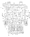
図1に示されているように、スクロール圧縮機1は、外郭を構成するハウジング2を備えている。このハウジング2は、前端側(図において左側)が開口され、後端側が密閉された円筒形状をなすものであり、前端側の開口にフロントハウジング3をボルト4で締め付け固定されることにより、内部に密閉空間を形成し、その密閉空間にスクロール圧縮機構5および駆動軸6が組み込まれるようになっている。
Hereinafter, embodiments according to the present invention will be described with reference to the drawings.
As shown in FIG. 1, the scroll compressor 1 includes a
駆動軸6は、フロントハウジング3に主軸受7および副軸受8を介して回転自在に支持されており、フロントハウジング3からメカニカルシール9を介して外部に突出された前端部に、フロントハウジング3の外周部に軸受10を介して回転自在に設置されたプーリ11が電磁クラッチ12を介して連結され、外部から動力が伝達可能とされている。この駆動軸6の後端には、所定寸法だけ偏心したクランクピン13が一体に設けられ、後述するスクロール圧縮機構5の旋回スクロール16と、その旋回半径を可変とするドライブブッシュおよびドライブ軸受を含む公知の従動クランク機構14を介して連結されている。
The
スクロール圧縮機構5は、一対の固定スクロール15と旋回スクロール16とを180°位相をずらして噛み合わせることにより、両スクロール15,16間に、固定スクロール15の中心を挟んで正対する一対の圧縮室17を形成し、その圧縮室17を外周位置から中心位置へと容積を漸次減じながら移動することにより流体(冷媒ガス)を圧縮するものである。固定スクロール15は、中心部位に圧縮したガスを吐出する吐出ポート18を備えており、ハウジング2の底壁面にボルト19を介して固定設置されている。また、旋回スクロール16は、駆動軸6のクランクピン13に従動クランク機構14を介して連結され、フロントハウジング3のスラスト軸受面に公知の自転阻止機構20を介して公転旋回駆動自在に支持されている。
The
固定スクロール15の端板15Aの外周には、Oリング21が設けられ、そのOリング21がハウジング2の内周面に密接されることにより、ハウジング2の内部空間が吐出チャンバー22と吸入チャンバー23とに区画されている。吐出チャンバー22には、吐出ポート18が開口され、圧縮室17からの圧縮ガスが吐出されるようになっており、そこから圧縮ガスが冷凍サイクル側へと吐出されるようになっている。また、吸入チャンバー23には、ハウジング2に設けられた吸入ポート24が開口されており、冷凍サイクルを循環した低圧ガスが吸込まれ、吸入チャンバー23を経て圧縮室17内に冷媒ガスが吸入されるようになっている。
An O-
一対の固定スクロール15と旋回スクロール16は、それぞれ端板15A,16A上に壁体として渦巻状ラップ15B,16Bが一体に立設された構成とされている。固定スクロール15の歯先面15Cが旋回スクロール16の歯底面16Dに接触し、旋回スクロール16の歯先面16Cが固定スクロール15の歯底面15Dに接触するようになっている。
旋回スクロール16の端板16Aには、その高さが渦巻状ラップ16Bの渦に沿ってその中心部側で高く外終端側で低くなるよう形成された端板側段差部16Eが設けられている。具体的には、図2に示すように、旋回スクロール16の渦巻状ラップ16Bの巻き終わりの位置から180°の位置に、端板側段差部16Eが設けられている。
The pair of fixed
The
固定スクロール15の渦巻状ラップ15Bには、上述の旋回スクロール16の端板側段差部16Eに対応し、高さが渦の中心部側で低く外終端側で高くなるラップ側段差部15Eが設けられている。具体的には、図2に示すように、固定スクロール15の渦巻状ラップ15Bの巻き終わりの位置から360°の位置に、ラップ側段差部15Eが設けられている。
The
すなわち、旋回スクロール16の端板16Aのみに端板側段差部16Eが設けられ、固定スクロール15の渦巻状ラップ15Bのみにラップ側段差部15Eが設けられている。したがって、旋回スクロール16の渦巻状ラップ16Bには段差部が設けられておらず、渦巻状ラップ16Bの先端は同一高さとされている。また、固定スクロール15の端板15Aには段差部が設けられておらず、フラットな面とされている。
That is, the end plate side stepped
図2に示すように、圧縮室17は、固定スクロール15の中心を挟んで正対する少なくとも1対の圧縮室17A,17Bから形成される。
As shown in FIG. 2, the
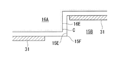
上述した固定スクロール15及び旋回スクロール16は、それぞれアルミ合金製とされている。固定スクロール15は、表面硬化処理が施されておらず、切削研磨後のアルミ合金材料が最表面層となっている。旋回スクロール16は、表面硬化処理として硬質アルマイト処理が施されている。したがって、図3及び図4に示すように、旋回スクロール16の端板側段差部16Eに硬質アルマイト層Cが形成されており、固定スクロール15のラップ側段差部15Eには表面硬化処理が施されていない。また、旋回スクロール16が固定スクロール15に対して公転旋回運動を行うと、図3に示すように、端板側段差部16Eとラップ側段差部15Eとが接触しながら相対的に移動する。したがって、ラップ側段差部15Eの先端の曲面が、この曲面よりも大きな半径とされた端板側段差部16Eの曲面に対して接触することになる。
表面硬化処理を行う範囲は、少なくとも固定スクロール15と接触する範囲とされ、好ましくは、渦巻状ラップ16Bの全体と、渦巻状ラップ16Bが設けられた側の端板16Aの全体を含む範囲とされる。もちろん、旋回スクロール16の全体に表面硬化処理を行ってもよい。
なお、図4における符号31は、渦巻状ラップ15Bの先端に形成された溝内に取り付けられて流体の漏れを防止するためのチップシールである。
The fixed
The range in which the surface hardening treatment is performed is at least a range in contact with the fixed
In addition, the code |
固定スクロール15の外終端側で高くなるように形成された渦巻状ラップ15Bの高さ、すなわちラップ側段差部15Eよりも外終側の高さをLout(図1参照)とし、旋回スクロール16の中心部側で高くなるように形成された端板側段差部16Eの高さ、すなわち端板側段差部16Eよりも中心部側の段差の高さをLs(図1参照)とした場合、Ls/Loutが0.05以上とされている。また、Ls/Loutは、好ましくは0.05以上0.3以下とされ、さらに好ましくは0.1以上0.2以下とされる。
The height of the
本実施形態のスクロール圧縮機1によれば、以下の作用効果を奏する。
固定スクロール15と旋回スクロール16とが噛み合って公転旋回運動を行うと、端板側段差部16Eに対してラップ側段差部15Eが接触しながら相対的に移動する。この場合、端板側段差部16Eの方が、これよりも小さな半径を有する曲面とされたラップ側段差部15Eよりも接触面積が大きくなるので、端板側段差部16Eに硬質アルマイト処理を施すことによって硬質アルマイト層Cの減耗を可及的に防止し、焼き付きを回避することができる。
また、ラップ側段差部15Eが設けられた渦巻状ラップ15Bは、ラップ側段差部15Eの根本15F(図4及び図5参照)に応力集中が生じる。一方、硬質アルマイト処理は表面の面粗度を悪化させるのでラップ側段差部15Eの根本15Fの疲労強度をさらに低下させてしまうおそれがある。そこで、ラップ側段差部15Eが設けられた固定スクロールには表面硬化処理を施さないこととし、疲労強度の向上を図っている。
According to the scroll compressor 1 of the present embodiment, the following effects are achieved.
When the fixed
Further, in the
また、中心部側の端板側段差部16Eの高さLsを外終端側の渦巻状ラップ15Bの高さLoutで除した値であるLs/Loutが0.05以上、好ましくは0.05以上0.3以下、さらに好ましくは0.1以上0.2以下としたので、Ls/Loutが大きい場合に段差の寸法が大きくなり圧縮流体が漏れる経路が増大することによる性能の低下のおそれを可及的に回避する一方で、Ls/Loutを小さくして段差の寸法を小さくした場合に、圧縮比が低下するだけでなく、中心部側の渦巻状ラップの高さが相対的に高くなり渦巻状ラップの強度が低下するおそれを可及的に回避することができる。
Further, Ls / Lout, which is a value obtained by dividing the height Ls of the end plate side stepped
なお、本実施形態では、旋回スクロール16の端板16Aのみに端板側段差部16Eが設けられ、固定スクロール15の渦巻状ラップ15Bのみにラップ側段差部15Eが設けられた構成を用いて説明したが、この逆の構成、すなわち、固定スクロール15の端板15Aのみに端板側段差部が設けられ、旋回スクロール16の渦巻状ラップ16Bのみにラップ側段差部が設けられた構成についても本発明を適用することができる。この場合には、固定スクロール15の表面硬化処理を行い、旋回スクロール16には表面硬化処理を行わない。
In the present embodiment, the end plate side stepped
また、本実施形態ではアルミ合金製のスクロール15,16について説明視したが、スクロール15,16が鋳鉄又は鉄の場合には、表面硬化処理としてはリン酸塩皮膜やDLC(Diamond Like Carbon)等が用いられる。
Further, in the present embodiment, the aluminum alloy scrolls 15 and 16 have been described, but in the case where the
また、本実施形態では、一方のスクロールのみに表面硬化処理を行うこととしたが、本発明は両方のスクロールに表面硬化処理を行う場合にも適用することができる。この場合には、端板側段差部が設けられた一方のスクロールに対して、他方のスクロールに施す表面硬化処理よりも硬い表面硬化処理を用いる。表面処理としては、例えば、硬い方の表面処理としてNi−P(ニッケル−リン)メッキが用いられ、他方にはSn(スズ)メッキが用いられる。 Further, in the present embodiment, the surface hardening treatment is performed on only one of the scrolls, but the present invention can also be applied to the case where the surface hardening treatment is performed on both scrolls. In this case, a surface hardening process harder than the surface hardening process applied to the other scroll is used for one scroll provided with the end plate side step portion. As the surface treatment, for example, Ni-P (nickel-phosphorus) plating is used as the surface treatment for the harder side, and Sn (tin) plating is used for the other side.
また、本発明は、特許文献1を用いて説明したような固定スクロール及び旋回スクロールの両側の端板に端板側段差部が設けられたスクロール圧縮機に対しても適用することができる。すなわち、旋回スクロールの端板に設けられた端板側段差部の高さが、固定スクロールの端板に設けられた端板側段差部よりも高い場合には、旋回スクロールに対して表面硬化処理を行い、固定スクロールには表面処理を行わない。あるいは、旋回スクロールに対して、固定スクロールに施す表面硬化処理よりも硬い表面硬化処理を用いる。
一方、固定スクロールの端板に設けられた端板側段差部の高さが、旋回スクロールの端板に設けられた端板側段差部よりも高い場合には、固定スクロールに対して表面硬化処理を行い、旋回スクロールには表面処理を行わない。あるいは、固定スクロールに対して、旋回スクロールに施す表面硬化処理よりも硬い表面硬化処理を用いる。
The present invention can also be applied to a scroll compressor in which end plate side step portions are provided on the fixed scroll and the end plates on both sides of the orbiting scroll as described using Patent Document 1. That is, when the height of the end plate side step portion provided on the end plate of the orbiting scroll is higher than the end plate side step portion provided on the end plate of the fixed scroll, the surface hardening process is performed on the orbiting scroll And do not surface treat fixed scrolls. Alternatively, for the orbiting scroll, a surface hardening treatment harder than the surface hardening treatment applied to the fixed scroll is used.
On the other hand, when the height of the end plate side step portion provided on the end plate of the fixed scroll is higher than the end plate side step portion provided on the end plate of the orbiting scroll, the surface hardening treatment is performed on the fixed scroll And no surface treatment on the orbiting scroll. Alternatively, for the fixed scroll, a surface hardening treatment that is harder than the surface hardening treatment applied to the orbiting scroll is used.
1 スクロール圧縮機
15 固定スクロール
16 旋回スクロール
15A,16A 端板
15B,16B 渦巻状ラップ
15C,16C 歯先面
15D,16D 歯底面
15E ラップ側段差部(壁体側段差部)
16E 端板側段差部
17 圧縮室
17A 腹側圧縮室
17B 背側圧縮室
Reference Signs List 1
16E end plate side stepped
Claims (5)
端板の一側面に立設された渦巻状の壁体を有し、前記各壁体どうしを噛み合わせて自転を阻止されつつ公転旋回運動可能に支持された旋回スクロールと、
両前記スクロールによって圧縮された流体が吐出される吐出ポートと、
を備え、
両前記スクロールのいずれか一方の端板には、前記一側面に、高さが壁体の渦に沿ってその中心部側で高く外終端側で低くなるように形成された端板側段差部が設けられ、
両前記スクロールの他方の壁体には、前記端板側段差部に対応し、高さが渦の中心部側で低く外終端側で高くなるように形成された壁体側段差部が設けられたスクロール圧縮機において、
前記端板側段差部が設けられた一方の前記スクロールには、表面硬化処理が施されており、他方の前記スクロールには、表面硬化処理が施されていないスクロール圧縮機。 A stationary scroll having a spiral wall standing on one side of the end plate;
An orbiting scroll having a spiral wall erected on one side of the end plate, the walls being meshed with each other to prevent rotation while being supported so as to be able to orbit and orbit;
A discharge port from which fluid compressed by the scrolls is discharged;
Equipped with
An end plate side stepped portion formed on one of the end plates of either of the scrolls so that the height is high along the vortex of the wall at the center and lower at the outer end. Is provided,
The other wall of the scrolls is provided with a wall-side step corresponding to the end plate-side step and having a height which is low at the center of the vortex and high at the outer end. In the scroll compressor ,
A scroll compressor in which a surface hardening treatment is applied to one of the scrolls provided with the end plate side step portion and a surface hardening treatment is not applied to the other scroll.
端板の一側面に立設された渦巻状の壁体を有し、前記各壁体どうしを噛み合わせて自転を阻止されつつ公転旋回運動可能に支持された旋回スクロールと、
両前記スクロールによって圧縮された流体が吐出される吐出ポートと、
を備え、
両前記スクロールのそれぞれの端板には、前記一側面に、高さが壁体の渦に沿ってその中心部側で高く外終端側で低くなるように形成された端板側段差部が設けられ、
両前記スクロールのそれぞれの壁体には、前記端板側段差部に対応し、高さが渦の中心部側で低く外終端側で高くなるように形成された壁体側段差部が設けられ、
一方の前記スクロールの前記端板側段差部と他方の前記スクロールの前記端板側段差部の高さが異なるスクロール圧縮機において、
前記端板側段差部の高さが大きい一方の前記スクロールには、表面硬化処理が施されており、他方の前記スクロールには、表面硬化処理が施されていないスクロール圧縮機。 A stationary scroll having a spiral wall standing on one side of the end plate;
An orbiting scroll having a spiral wall erected on one side of the end plate, the walls being meshed with each other to prevent rotation while being supported so as to be able to orbit and orbit;
A discharge port from which fluid compressed by the scrolls is discharged;
Equipped with
Each end plate of both scrolls is provided with an end plate side stepped portion formed on one side surface so that the height is high along the center of the wall along the vortex of the wall and lower on the outer end side. And
Each wall of both scrolls is provided with a wall-side step corresponding to the end-plate-side step and formed such that the height is low on the center side of the vortex and high on the outer end side,
In a scroll compressor in which heights of the end plate side step portion of one of the scrolls and the end plate side step portion of the other scroll of the scroll are different,
A surface-hardening treatment is given to one said scroll with the large height of the said end plate side level | step-difference part, and the scroll compressor with which the surface hardening treatment is not given to the said other said scroll.
端板の一側面に立設された渦巻状の壁体を有し、前記各壁体どうしを噛み合わせて自転を阻止されつつ公転旋回運動可能に支持された旋回スクロールと、
両前記スクロールによって圧縮された流体が吐出される吐出ポートと、
を備え、
両前記スクロールのいずれか一方の端板には、前記一側面に、高さが壁体の渦に沿ってその中心部側で高く外終端側で低くなるように形成された端板側段差部が設けられ、
両前記スクロールの他方の壁体には、前記端板側段差部に対応し、高さが渦の中心部側で低く外終端側で高くなるように形成された壁体側段差部が設けられたスクロール圧縮機において、
前記端板側段差部が設けられた一方の前記スクロールには、他方の前記スクロールに施された表面硬化処理よりも硬い表面硬化処理が施されているスクロール圧縮機。 A stationary scroll having a spiral wall standing on one side of the end plate;
An orbiting scroll having a spiral wall erected on one side of the end plate, the walls being meshed with each other to prevent rotation while being supported so as to be able to orbit and orbit;
A discharge port from which fluid compressed by the scrolls is discharged;
Equipped with
An end plate side stepped portion formed on one of the end plates of either of the scrolls so that the height is high along the vortex of the wall at the center and lower at the outer end. Is provided,
The other wall of the scrolls is provided with a wall-side step corresponding to the end plate-side step and having a height which is low at the center of the vortex and high at the outer end. In the scroll compressor,
A scroll compressor in which a surface hardening process harder than a surface hardening process applied to the other scroll is applied to one of the scrolls provided with the end plate side step portion.
端板の一側面に立設された渦巻状の壁体を有し、前記各壁体どうしを噛み合わせて自転を阻止されつつ公転旋回運動可能に支持された旋回スクロールと、
両前記スクロールによって圧縮された流体が吐出される吐出ポートと、
を備え、
両前記スクロールのそれぞれの端板には、前記一側面に、高さが壁体の渦に沿ってその中心部側で高く外終端側で低くなるように形成された端板側段差部が設けられ、
両前記スクロールのそれぞれの壁体には、前記端板側段差部に対応し、高さが渦の中心部側で低く外終端側で高くなるように形成された壁体側段差部が設けられ、
一方の前記スクロールの前記端板側段差部と他方の前記スクロールの前記端板側段差部の高さが異なるスクロール圧縮機において、
前記端板側段差部の高さが大きい一方の前記スクロールには、他方の前記スクロールよりも硬い表面硬化処理が施されているスクロール圧縮機。 A stationary scroll having a spiral wall standing on one side of the end plate;
An orbiting scroll having a spiral wall erected on one side of the end plate, the walls being meshed with each other to prevent rotation while being supported so as to be able to orbit and orbit;
A discharge port from which fluid compressed by the scrolls is discharged;
Equipped with
Each end plate of both scrolls is provided with an end plate side stepped portion formed on one side surface so that the height is high along the center of the wall along the vortex of the wall and lower on the outer end side. And
Each wall of both scrolls is provided with a wall-side step corresponding to the end-plate-side step and formed such that the height is low on the center side of the vortex and high on the outer end side,
In a scroll compressor in which heights of the end plate side step portion of one of the scrolls and the end plate side step portion of the other scroll of the scroll are different,
The scroll compressor in which a surface hardening process harder than the other said scroll is given to one said scroll with the large height of the said end plate side level | step-difference part.
Ls/Loutが0.05以上とされている請求項1から4のいずれかに記載のスクロール圧縮機。 Assuming that the height of the wall formed to be higher on the outer end side is Lout, and the height of the end plate side stepped portion formed to be higher on the central side is Ls,
The scroll compressor according to any one of claims 1 to 4, wherein Ls / Lout is 0.05 or more.
Priority Applications (6)
| Application Number | Priority Date | Filing Date | Title |
|---|---|---|---|
| JP2015049877A JP6532713B2 (en) | 2015-03-12 | 2015-03-12 | Scroll compressor |
| CN201680014200.XA CN107429691B (en) | 2015-03-12 | 2016-03-08 | scroll compressor |
| DE112016001173.3T DE112016001173B4 (en) | 2015-03-12 | 2016-03-08 | spiral compressor |
| PCT/JP2016/057082 WO2016143768A1 (en) | 2015-03-12 | 2016-03-08 | Scroll compressor |
| US15/552,959 US11092155B2 (en) | 2015-03-12 | 2016-03-08 | Scroll compressor including fixed and orbiting scrolls having different heights and surface hardenings |
| US17/159,741 US11939977B2 (en) | 2015-03-12 | 2021-01-27 | Scroll compressor including fixed and orbiting scroll having stepped portions and a surface hardened treatment |
Applications Claiming Priority (1)
| Application Number | Priority Date | Filing Date | Title |
|---|---|---|---|
| JP2015049877A JP6532713B2 (en) | 2015-03-12 | 2015-03-12 | Scroll compressor |
Publications (3)
| Publication Number | Publication Date |
|---|---|
| JP2016169661A JP2016169661A (en) | 2016-09-23 |
| JP2016169661A5 JP2016169661A5 (en) | 2018-02-08 |
| JP6532713B2 true JP6532713B2 (en) | 2019-06-19 |
Family
ID=56880308
Family Applications (1)
| Application Number | Title | Priority Date | Filing Date |
|---|---|---|---|
| JP2015049877A Active JP6532713B2 (en) | 2015-03-12 | 2015-03-12 | Scroll compressor |
Country Status (5)
| Country | Link |
|---|---|
| US (2) | US11092155B2 (en) |
| JP (1) | JP6532713B2 (en) |
| CN (1) | CN107429691B (en) |
| DE (1) | DE112016001173B4 (en) |
| WO (1) | WO2016143768A1 (en) |
Families Citing this family (4)
| Publication number | Priority date | Publication date | Assignee | Title |
|---|---|---|---|---|
| KR102630534B1 (en) | 2022-01-14 | 2024-01-29 | 엘지전자 주식회사 | Scroll compressor |
| CN116950894B (en) * | 2022-04-20 | 2025-12-05 | 谷轮环境科技(苏州)有限公司 | Scroll components, compression mechanism and scroll compressor |
| KR102652594B1 (en) | 2022-05-06 | 2024-04-01 | 엘지전자 주식회사 | Scroll compressor |
| JP7795696B2 (en) | 2022-07-22 | 2026-01-08 | サンデン株式会社 | Scroll Compressor |
Family Cites Families (18)
| Publication number | Priority date | Publication date | Assignee | Title |
|---|---|---|---|---|
| JPS6017956B2 (en) | 1981-08-18 | 1985-05-08 | サンデン株式会社 | Scroll compressor |
| JPH04121483A (en) | 1990-09-12 | 1992-04-22 | Toshiba Corp | Scroll type compressor |
| JP3137507B2 (en) * | 1993-08-30 | 2001-02-26 | 三菱重工業株式会社 | Scroll type fluid machine |
| JP3684247B2 (en) * | 1995-01-24 | 2005-08-17 | 株式会社豊田自動織機 | Scroll compressor and method for manufacturing the same |
| JP4410392B2 (en) | 2000-06-22 | 2010-02-03 | 三菱重工業株式会社 | Scroll compressor |
| KR100460396B1 (en) * | 2000-06-22 | 2004-12-08 | 미츠비시 쥬고교 가부시키가이샤 | Scroll compressor |
| JP4709400B2 (en) * | 2001-01-18 | 2011-06-22 | 三菱重工業株式会社 | Scroll compressor |
| JP3961274B2 (en) * | 2001-12-05 | 2007-08-22 | 松下電器産業株式会社 | Compressor |
| US7905715B2 (en) * | 2003-06-17 | 2011-03-15 | Panasonic Corporation | Scroll compressor having a fixed scroll part and an orbiting scroll part |
| CN100371598C (en) * | 2003-08-11 | 2008-02-27 | 三菱重工业株式会社 | Scroll compressor |
| KR100695822B1 (en) * | 2004-12-23 | 2007-03-20 | 엘지전자 주식회사 | Stepped Capacity Variable Speed Scroll Compressor |
| JP4813938B2 (en) * | 2006-03-20 | 2011-11-09 | 三菱重工業株式会社 | Scroll compressor |
| JP2008151009A (en) * | 2006-12-15 | 2008-07-03 | Mitsubishi Heavy Ind Ltd | Scroll compressor |
| JP5030581B2 (en) * | 2006-12-28 | 2012-09-19 | 三菱重工業株式会社 | Scroll compressor |
| JP4814189B2 (en) * | 2007-09-21 | 2011-11-16 | 三菱重工業株式会社 | Scroll compressor |
| JP5393063B2 (en) * | 2008-06-10 | 2014-01-22 | 三菱重工業株式会社 | Scroll compressor |
| JP6053349B2 (en) | 2012-06-27 | 2016-12-27 | 三菱重工業株式会社 | Scroll compressor |
| JP6214954B2 (en) * | 2013-07-25 | 2017-10-18 | 三菱重工業株式会社 | Scroll compressor |
-
2015
- 2015-03-12 JP JP2015049877A patent/JP6532713B2/en active Active
-
2016
- 2016-03-08 US US15/552,959 patent/US11092155B2/en active Active
- 2016-03-08 DE DE112016001173.3T patent/DE112016001173B4/en active Active
- 2016-03-08 CN CN201680014200.XA patent/CN107429691B/en active Active
- 2016-03-08 WO PCT/JP2016/057082 patent/WO2016143768A1/en not_active Ceased
-
2021
- 2021-01-27 US US17/159,741 patent/US11939977B2/en active Active
Also Published As
| Publication number | Publication date |
|---|---|
| US11939977B2 (en) | 2024-03-26 |
| JP2016169661A (en) | 2016-09-23 |
| US20180038368A1 (en) | 2018-02-08 |
| US20210148361A1 (en) | 2021-05-20 |
| WO2016143768A1 (en) | 2016-09-15 |
| DE112016001173B4 (en) | 2025-10-30 |
| CN107429691B (en) | 2019-06-21 |
| DE112016001173T5 (en) | 2017-11-30 |
| US11092155B2 (en) | 2021-08-17 |
| CN107429691A (en) | 2017-12-01 |
Similar Documents
| Publication | Publication Date | Title |
|---|---|---|
| KR0125462B1 (en) | Scroll fluid machine | |
| US11939977B2 (en) | Scroll compressor including fixed and orbiting scroll having stepped portions and a surface hardened treatment | |
| RU2560647C1 (en) | Scroll compressor | |
| US9732753B2 (en) | Scroll compressor with inclined surfaces on the stepped portions | |
| US10087758B2 (en) | Rotary machine | |
| JP3924817B2 (en) | Positive displacement fluid machine | |
| US10208749B2 (en) | Scroll compressor with a ring member and guide pin | |
| CN105705792B (en) | Scroll-type fluid machine | |
| JP6758969B2 (en) | Stepped scroll compressor and its design method | |
| CN113544383A (en) | scroll compressor | |
| JP6906887B2 (en) | Scroll fluid machine | |
| WO2013108866A1 (en) | Tip seal and scroll compressor utilizing same | |
| JP2008267149A (en) | Fluid machine | |
| WO2016140107A1 (en) | Scroll fluid machine | |
| WO2016043132A1 (en) | Scroll-type fluid machine | |
| JP2009127524A (en) | Scroll compressor | |
| JP6685649B2 (en) | Scroll compressor | |
| JP6599099B2 (en) | Scroll fluid machinery | |
| JP5791316B2 (en) | Scroll type fluid machinery | |
| JP7454786B2 (en) | scroll compressor | |
| JP6214875B2 (en) | Scroll compressor and method of processing the scroll | |
| JP6932797B2 (en) | Scroll compressor | |
| JP6617070B2 (en) | Scroll type liquid pump | |
| JP2010150966A (en) | Scroll compressor | |
| JP2002276575A (en) | Fluid machinery |
Legal Events
| Date | Code | Title | Description |
|---|---|---|---|
| A521 | Request for written amendment filed |
Free format text: JAPANESE INTERMEDIATE CODE: A523 Effective date: 20171220 |
|
| A621 | Written request for application examination |
Free format text: JAPANESE INTERMEDIATE CODE: A621 Effective date: 20171220 |
|
| A711 | Notification of change in applicant |
Free format text: JAPANESE INTERMEDIATE CODE: A712 Effective date: 20180612 |
|
| A131 | Notification of reasons for refusal |
Free format text: JAPANESE INTERMEDIATE CODE: A131 Effective date: 20181009 |
|
| A521 | Request for written amendment filed |
Free format text: JAPANESE INTERMEDIATE CODE: A523 Effective date: 20181210 |
|
| TRDD | Decision of grant or rejection written | ||
| A01 | Written decision to grant a patent or to grant a registration (utility model) |
Free format text: JAPANESE INTERMEDIATE CODE: A01 Effective date: 20190423 |
|
| A61 | First payment of annual fees (during grant procedure) |
Free format text: JAPANESE INTERMEDIATE CODE: A61 Effective date: 20190522 |
|
| R150 | Certificate of patent or registration of utility model |
Ref document number: 6532713 Country of ref document: JP Free format text: JAPANESE INTERMEDIATE CODE: R150 |