EP0723624B1 - Reciprocable device - Google Patents
Reciprocable device Download PDFInfo
- Publication number
- EP0723624B1 EP0723624B1 EP94930054A EP94930054A EP0723624B1 EP 0723624 B1 EP0723624 B1 EP 0723624B1 EP 94930054 A EP94930054 A EP 94930054A EP 94930054 A EP94930054 A EP 94930054A EP 0723624 B1 EP0723624 B1 EP 0723624B1
- Authority
- EP
- European Patent Office
- Prior art keywords
- valve
- reciprocable
- chamber
- driving
- piston
- Prior art date
- Legal status (The legal status is an assumption and is not a legal conclusion. Google has not performed a legal analysis and makes no representation as to the accuracy of the status listed.)
- Expired - Lifetime
Links
- 239000012530 fluid Substances 0.000 claims description 52
- 230000008878 coupling Effects 0.000 claims description 24
- 238000010168 coupling process Methods 0.000 claims description 24
- 238000005859 coupling reaction Methods 0.000 claims description 24
- 238000005086 pumping Methods 0.000 claims description 16
- 230000007935 neutral effect Effects 0.000 claims description 14
- 238000007789 sealing Methods 0.000 claims description 12
- 238000005192 partition Methods 0.000 claims description 3
- 230000001419 dependent effect Effects 0.000 claims 3
- 230000008901 benefit Effects 0.000 description 4
- 230000000977 initiatory effect Effects 0.000 description 3
- 238000010276 construction Methods 0.000 description 2
- 230000004941 influx Effects 0.000 description 2
- 230000001133 acceleration Effects 0.000 description 1
- 230000009471 action Effects 0.000 description 1
- 230000009969 flowable effect Effects 0.000 description 1
- 239000007788 liquid Substances 0.000 description 1
- 239000000463 material Substances 0.000 description 1
- 230000007246 mechanism Effects 0.000 description 1
- 238000000034 method Methods 0.000 description 1
- 230000004044 response Effects 0.000 description 1
- 230000000717 retained effect Effects 0.000 description 1
- 229910001220 stainless steel Inorganic materials 0.000 description 1
- 239000010935 stainless steel Substances 0.000 description 1
- 239000002699 waste material Substances 0.000 description 1
Images

Classifications
-
- F—MECHANICAL ENGINEERING; LIGHTING; HEATING; WEAPONS; BLASTING
- F01—MACHINES OR ENGINES IN GENERAL; ENGINE PLANTS IN GENERAL; STEAM ENGINES
- F01B—MACHINES OR ENGINES, IN GENERAL OR OF POSITIVE-DISPLACEMENT TYPE, e.g. STEAM ENGINES
- F01B11/00—Reciprocating-piston machines or engines without rotary main shaft, e.g. of free-piston type
- F01B11/004—Reciprocating-piston machines or engines without rotary main shaft, e.g. of free-piston type in which the movement in the two directions is obtained by two single acting piston motors, each acting in one direction
-
- F—MECHANICAL ENGINEERING; LIGHTING; HEATING; WEAPONS; BLASTING
- F01—MACHINES OR ENGINES IN GENERAL; ENGINE PLANTS IN GENERAL; STEAM ENGINES
- F01L—CYCLICALLY OPERATING VALVES FOR MACHINES OR ENGINES
- F01L23/00—Valves controlled by impact by piston, e.g. in free-piston machines
-
- F—MECHANICAL ENGINEERING; LIGHTING; HEATING; WEAPONS; BLASTING
- F04—POSITIVE - DISPLACEMENT MACHINES FOR LIQUIDS; PUMPS FOR LIQUIDS OR ELASTIC FLUIDS
- F04B—POSITIVE-DISPLACEMENT MACHINES FOR LIQUIDS; PUMPS
- F04B9/00—Piston machines or pumps characterised by the driving or driven means to or from their working members
- F04B9/08—Piston machines or pumps characterised by the driving or driven means to or from their working members the means being fluid
- F04B9/12—Piston machines or pumps characterised by the driving or driven means to or from their working members the means being fluid the fluid being elastic, e.g. steam or air
- F04B9/123—Piston machines or pumps characterised by the driving or driven means to or from their working members the means being fluid the fluid being elastic, e.g. steam or air having only one pumping chamber
- F04B9/1235—Piston machines or pumps characterised by the driving or driven means to or from their working members the means being fluid the fluid being elastic, e.g. steam or air having only one pumping chamber the movement of the pump piston in the two directions being obtained by two single-acting piston fluid motors, each acting in one direction
Definitions
- This invention relates to reciprocable devices, and more particularly to a reciprocable device having an improved valving system for ensuring dependable switching of the reciprocable member travel direction during operation.
- Reciprocable devices typically include a reciprocable member which reciprocates to perform a useful function, such as pumping a flowable material, compressing a gas, metering a fluid or providing a reciprocating output for other purposes.
- a driving fluid under pressure which may be either a liquid or a gas, is commonly used to reciprocate the reciprocable member.
- the reciprocable member may be a piston having first and second faces which are alternately exposable to driving fluid under pressure and to exhaust.
- a valve or valving system is provided for controlling the exposure of the piston faces to the pressurized driving fluid and to exhaust.
- the valve system In order for the valve system to perform its function, it typically includes one or more valve elements which must be moved periodically from one position to another to bring about reciprocation of the piston. Movement of the reciprocable member can be used to control movement of the valve elements.
- Reciprocating devices of the type described are shown, for example, in U.S. Pat. No. 4,610,192 to Hartley et al.
- the construction disclosed therein employs a bistable toggle mechanism which is driven just over center by energy from the piston and then driven by stored spring energy.
- the toggle action reverses the pressure and exhaust valves to bring about a reversal of movement of the reciprocable member.
- the valves in this prior art system are fluid pressure biased.
- a further reciprocating device is disclosed in U.S. Pat. No. 3,768,932 to Sverel et al.
- This device is constructed in accordance with the preamble of the appended claim 1.
- the reciprocable member is unable to apply a direct mechanical backup force to the valve in the event that the valve becomes jammed.
- the force which may be applied to the valve in such circumstances is limited by the extent to which connecting springs may be compressed.
- the backup drive of the prior art device can often therefore be ineffective at releasing a jammed valve.
- the present invention provides a reciprocable device comprising: a housing having a chamber therein; a reciprocable member in the chamber and having first and second faces exposable to a driving fluid under pressure to reciprocate the reciprocable member in the chamber; a valve having first and second states for controlling the supply and exhaust of the driving fluid under pressure to and from the first and second faces whereby the reciprocable member can be reciprocated in said chamber; an actuator for drivingly coupling the reciprocable member and the valve; and a bistable spring device having first and second states and a neutral position between said states thereof; said bistable spring device being coupled to said actuator such that said reciprocable member can move the bistable spring device from one of its states through the neutral position, with the resilience of the bistable spring device at least assisting in moving the bistable spring device from its neutral position to the other state thereof; movement of said bistable spring device to said other state at least assisting in switching the valve from one of its states to another so that the reciprocable member reverses direction; characterised in that, if said bistable spring device is initially unable to exert
- a device according to the present invention provides a valving system for a reciprocable device of the type discussed which is even easier to switch over, does not require a strong spring force to actuate, and provides for a mechanical backup in case of a valve jam, so that valve switchover and consequent dependable operation of the reciprocable device is assured.
- the driving fluid under pressure which drives the reciprocable member in both directions.
- the reciprocable member is driven in both directions solely by the fluid under pressure.
- one or more drive springs can be employed to assist in driving the reciprocable member, none is required.
- a spool valve, and particularly a spool valve having the features described below, is relatively easy to move. This coupled with the lack of any need for a drive spring which would be compressed and therefore take energy from the system as the reciprocable member moves in one direction, reduce the likelihood of stalling due to failure of the valving system to switch over.
- bistable spring device fails for some reason to complete the switching of the valving system from one of its positions to the other one. Should this condition occur, because of a jammed valve or some other mishap, the reciprocable member continues its movement in the same axial direction, thereby eventually causing actuation of the valving system to its other position by means of a substantially rigid driving connection between the reciprocable member and the valve.
- This feature of the invention preferably employs, but does require a spool valve.
- the spool valve is preferably constructed such that the valve body includes on its outer surface thereof a plurality of alternating annular lands and grooves, with the lands each including a sealing surface thereon, such as an o-ring.
- the valve body is slidable axially within a valve chamber, with alternating annular undercuts or grooves and lands being arranged on the inner wall surface defining the chamber. In both of the spool valve's operating positions, the valve body lands are sealingly engaged with corresponding lands on the valve chamber surface, and to move from one position to the other the valve body travels axially a distance equivalent to the distance between two adjacent valve chamber lands.
- the spool valve is hydraulically balanced without a substantial fluid pressure bias when in either of its first and second positions.
- the valve is held in each of its two operating positions only by virtue of a biasing force from the bistable spring device, which biases the valve body against a stop means until the initiation of valve switchover, as well as the friction generated by the sealing engagement between each o-ring and its corresponding valve chamber land. Consequently, a relatively low spring force is required to initiate movement of the spool valve between positions.
- annular undercuts or grooves between the valve chamber lands which serve as fluid inlet and outlet ports for the spool valve, rather than the simple drilled bores which are typically used in the prior art.
- the significance of this feature is that the annular undercuts provide a substantially frictionless travel path for the o-rings between adjacent valve chamber lands.
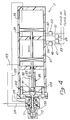
- FIGS. 1 through 5 show a reciprocable device 11 (FIGS. 2 and 4) which includes a housing 13 defining a chamber or cylinder 15 in which a reciprocable member or piston 17 is slidably mounted for reciprocating movement.
- the piston 17 could also comprise a diaphragm, bellows, or the like.
- the reciprocable device is a pump; however, the reciprocable device may be a compressor, meter or serve some other purpose.
- the piston 17 can be of different constructions, in the form illustrated, it includes piston sections 19 and 21 joined together by a shaft 23 and having driving faces 25 and 27 and pumping faces 29 and 31. With this arrangement, the chamber 15 is divided into driving chambers 33 and 35 at the opposite ends of the piston 17 and pumping chambers 37 and 39 between the piston sections 19 and 21 and a partition 41.
- a spool valve 43 controls the supply of driving fluid under pressure from a supply source 45 to the driving chambers 33 and 35, and also controls the exhausting of the driving chambers 33 and 35 to atmosphere or other place of reduced pressure.
- fluid in the pumping chamber 37 is forced by the piston section 19 through an outlet line 47 and an outlet check valve 48 to a location where it is to be utilized, and fluid is drawn in through an inlet check valve 49 and an inlet line 50 into the pumping chamber 39.
- the piston 17 reverses the fluid in the pumping chamber 39 is forced by the piston section 21 through an outlet line 51 and an outlet check valve 52, and fluid is drawn in to the pumping chamber 37 through an inlet check valve 53 and an inlet line 54.
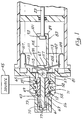
- the spool valve 43 comprises a valve housing 55 (FIG. 1) having an inner wall surface 56 which defines a generally cylindrical valve chamber 57.
- the inner wall surface 56 of the valve housing 55 is comprised of a series of alternating annular lands 58 and annular undercuts or grooves 59.
- Slidably mounted axially about a rod 61 within the valve chamber 57 is a spool valve body 63 which has an exterior surface 65 formed of an alternating series of annular lands 67 and grooves 69.
- a plurality of o-rings 71 which are oriented so that when the valve body 63 is stopped in a position wherein the valve housing lands 58 and the valve body lands 67 are aligned, each land 58 is in sealing engagement with a respective o-ring 71.
- the rod 61 and the valve body 63 are spaced by an annular gap 72, so that the rod 61 may move axially independently of the valve body 63.
- the rod 61 extends leftwardly out of the valve chamber 57 into a driving fluid exhaust plenum 73.
- a bumper nut 75 On the leftmost end of the rod 61 is threadedly mounted a bumper nut 75 which is guided axially within the plenum 73 by a plurality of stop ribs 77 mounted longitudinally on the surface defining the plenum 73.
- the spool valve rod 61 also extends rightwardly out of the valve chamber 57 through an opening 79 in an end plate 81.
- This rod extension portion 83 includes a pair of stepped diameter increases 85 and 87 (FIG. 3) culminating in a large diameter coupling portion 89.
- the coupling portion 89 of the rod extension portion 83 is attached to the leftmost end or attachment portion 93 of the piston shaft 23, in such a manner as to ensure that there is lost motion between the two elements.
- the attachment portion 93 of the shaft 23 has a greater diameter than the remainder of the shaft and is received within a lost motion chamber 95 in the coupling portion 89 of the rod 61.
- the attachment portion 93 of the shaft 23 moves axially within the chamber 95 until it contacts one of two chamber walls 99 and 101, after which, by virtue of the contact between the coupling portion 89 and the attachment portion 93, the coupling portion 89 is either pushed or pulled to reciprocate in response to the reciprocation of the piston 17.
- the reciprocable device 11 includes a bistable spring device 102, comprising identical rigid levers 103 and 105, which may be constructed of stainless steel, and identical U-shaped springs 107 and 109 which are mounted within respective chambers 111 and 113.
- the levers 103 and 105 have tabs (not shown) on the outer ends thereof, which are received by openings (not shown) in the U-shaped springs 107 and 109, thereby attaching the levers 103 and 105 to the springs 107 and 109 so that the levers are biased towards the coupling portion 89.
- Such an attachment scheme is shown and disclosed in U.S. Patent No. 4,610,192, herein incorporated by reference.
- the springs 107 and 109 may be integrated into one spring, interconnected by a web such as that shown in the 4,610,192 patent, or may be distinct spring elements, as shown.
- the coupling portion 89 has recesses 115 and 117 which progressively widen as they extend radially toward the periphery of the coupling portion 89 and this allows each of the levers to pivot about a pivot axis at the inner end of the associated recess. Because the levers 103 and 105 are biased toward the coupling portion 89, it forms pivot axes for the levers by virtue of the progressively widening nature of each of the recesses 115 and 117.
- the spool valve body 63 is seated against the stop ribs 77 and held in position by the spring device 102.
- Driving fluid under pressure is supplied from the supply source 45 through a fluid line 119 into an annular chamber portion 121 of the spool valve 43.
- the spool valve body 63 is in a first position at this juncture, permitting the fluid to exit the chamber portion 121 via a fluid line 123 which communicates with the driving chamber 33.
- the influx of pressurized driving fluid into the driving chamber 33 drives the piston 17 to the right, thereby causing pressurized pumping fluid to exit pumping chamber 37 through exhaust line 47 and driving fluid to be exhausted from driving chamber 35 through an exhaust line 125 which communicates with an annular chamber portion 126 of the spool valve 43. From the annular chamber portion 126, the exhaust fluid flows through an exhaust passage 127 to atmosphere, a waste sump, or some other low pressure application. With regard to the bistable spring device 102, it is apparent that the movement of the piston 17 to the right moves the attachment portion 93 to the right through the chamber 95, until it impacts the end wall 101 of the coupling portion 89.
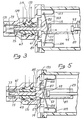
- FIG. 3 shows the device with the piston 17 beginning its leftward travel, and the spool valve body 63 having been translated into its second axial position.
- the resilience of the springs 107 and 109 rapidly forces the levers farther over center and into their second position, pivoted to the right.
- This rapid movement of the levers 103 and 105 becomes stronger as the levers travel farther past the over center point, pushing the coupling portion 89 and the associated rod 61 equally rapidly to the right, thereby initiating movement of the spool valve body to its second axial position by virtue of a small impact of the bumper 75 on the spool valve body 63.
- the exhaust chamber 73 acts as another lost motion device, ensuring in conjunction with the lost motion chamber 95 that the spool valve 43 is not actuated to its alternate position until the piston 17 has traveled a sufficient stroke distance.
- the spring biased levers 103 and 105 are arranged to form an over center device, in order to provide the impetus necessary to move the spool valve 43 from one to another of its two positions.
- a mechanical backup to ensure the proper operation of the over center device. If for any reason switchover is not initially achieved by the bistable spring device 102, an advantage of the instant invention over the prior art is that the piston itself provides a backup means for ensuring that the bistable spring device 102 is able to switch the valve to its alternate position.
- the reciprocable device 11 is shown with the valve 43 in its second position. Consequently, because of the repositioned o-rings 71, the pressurized driving fluid from the supply line 119 is delivered into a different annular chamber portion 129.
- the flow line 123 into the driving chamber 33 is now shut off from the supply line 119 by an intervening o-ring 71, and the fluid is now redirected into the fluid line 125 which communicates with the other driving chamber 35.
- the influx of pressurized driving fluid into the driving chamber 35 reverses the travel direction of the piston, driving it to the left, thereby causing pressurized pumping fluid to exit pumping chamber 39 through exhaust line 51 and driving fluid to be exhausted from the driving chamber 33 through the fluid line 123.
- the fluid line 123 communicates with the exhaust plenum 73 through an annular chamber portion 130 of the spool valve 43, as shown.
- the movement of the piston 17 back to the left moves the attachment portion 93 to the left through the chamber 95, until it impacts the end wall 99 of the coupling portion 89. This impact begins to push the coupling portion 89 to the left, thereby pivoting the levers 103 and 105 through their neutral position, and also pushing the spool valve rod 61 to the left as shown in FIG. 5.
- FIG. 5 shows the attachment portion 93 of the piston shaft 23 beginning its rightward motion again as a result of the valve switchover, it having already moved rightwardly away from abutting contact with the end wall 99.
- the spring biased levers 103 and 105 provide the impetus necessary to move the spool valve 43 from one to another of its two positions.
- the piston 17 provides a mechanical backup to ensure that the switchover occurs. Should the spring device 102, moving from its neutral position to its over center position as disclosed above, fail to complete movement of the valve 43 from its second to its first position, because of a valve jam or the like, the piston 17 will continue to move toward the left.
- Yet another key aspect of this invention is the advantageous configuration of the spool valve 43 in that it is hydraulically balanced.
- the valves are biased by the fluid pressure in the system, requiring a larger bistable spring force to overcome the fluid pressure bias in order to switch the valves.
- a strong spring must be used to assure switching of the valves. This relatively high spring force holds the reciprocable member in either of two positions even when the device is not in use, and as a consequence, the seating surfaces of the valves tend to take an undesirable permanent set.
- the spool valve 43 is designed to be held in either of its positions merely by virtue of the relatively small spring force created by the bistable spring, which holds the valve body 63 in position prior to initiation of valve switching, in order to eliminate the possibility of unintentional switching.
- the friction developed by the sealing engagement between the o-rings 71 and their corresponding lands 58 also serves as a secondary means for holding the valve body in position.
- the bistable spring 102 need only overcome this frictional force to initiate movement of the valve body 63 from one position to another, permitting the use of a less powerful spring.
- An additional advantage of the present invention is the use of the fully annular grooves or undercuts 59 to provide the inlet and outlet fluid flow passages for the spool valve 43, rather than simple drilled bores that are typically used in the prior art.
- the advantage of the annular undercuts is that as the valve body 63 travels axially from one of its positions to the other one, each of the o-rings 71 moving from one land 58 to the next, the o-rings encounter no friction as they travel over the annular undercuts.
- valve body 63 once a sufficient force has been applied to the valve body 63 to initiate motion thereof, overcoming the friction due to the sealing engagement between each of the o-rings 71 and its corresponding land 58, the valve body will have sufficient momentum, from the acceleration caused by the release of energy from the bistable spring, to travel an axial distance equivalent to the distance between lands 58, and thus sufficient to move into its other position. The frictionless travel of the o-rings across the undercuts 59 will not degrade that momentum.
Landscapes
- Engineering & Computer Science (AREA)
- Mechanical Engineering (AREA)
- General Engineering & Computer Science (AREA)
- Multiple-Way Valves (AREA)
- Fluid-Driven Valves (AREA)
Priority Applications (1)
| Application Number | Priority Date | Filing Date | Title |
|---|---|---|---|
| EP01112058A EP1130216A3 (en) | 1993-10-13 | 1994-10-05 | Reciprocable device |
Applications Claiming Priority (3)
| Application Number | Priority Date | Filing Date | Title |
|---|---|---|---|
| US135791 | 1993-10-13 | ||
| US08/135,791 US5505593A (en) | 1993-10-13 | 1993-10-13 | Reciprocable device with switching mechanism |
| PCT/US1994/011321 WO1995010690A1 (en) | 1993-10-13 | 1994-10-05 | Reciprocable device |
Related Child Applications (1)
| Application Number | Title | Priority Date | Filing Date |
|---|---|---|---|
| EP01112058A Division EP1130216A3 (en) | 1993-10-13 | 1994-10-05 | Reciprocable device |
Publications (2)
| Publication Number | Publication Date |
|---|---|
| EP0723624A1 EP0723624A1 (en) | 1996-07-31 |
| EP0723624B1 true EP0723624B1 (en) | 2003-05-02 |
Family
ID=22469684
Family Applications (2)
| Application Number | Title | Priority Date | Filing Date |
|---|---|---|---|
| EP94930054A Expired - Lifetime EP0723624B1 (en) | 1993-10-13 | 1994-10-05 | Reciprocable device |
| EP01112058A Withdrawn EP1130216A3 (en) | 1993-10-13 | 1994-10-05 | Reciprocable device |
Family Applications After (1)
| Application Number | Title | Priority Date | Filing Date |
|---|---|---|---|
| EP01112058A Withdrawn EP1130216A3 (en) | 1993-10-13 | 1994-10-05 | Reciprocable device |
Country Status (5)
| Country | Link |
|---|---|
| US (1) | US5505593A (enExample) |
| EP (2) | EP0723624B1 (enExample) |
| DE (1) | DE69432594T2 (enExample) |
| TW (1) | TW285702B (enExample) |
| WO (1) | WO1995010690A1 (enExample) |
Families Citing this family (30)
| Publication number | Priority date | Publication date | Assignee | Title |
|---|---|---|---|---|
| US6446682B1 (en) * | 1995-06-06 | 2002-09-10 | James P. Viken | Auto-loading fluid exchanger and method of use |
| US6223790B1 (en) | 1998-04-29 | 2001-05-01 | James P. Viken | Auto-Loading fluid exchanger and method of use |
| US5833925A (en) * | 1996-11-13 | 1998-11-10 | Beckman Instruments, Inc. | Automatic chemistry analyzer with improved ion selective electrode assembly |
| JP3180706B2 (ja) * | 1997-03-07 | 2001-06-25 | 株式会社島津製作所 | 送液ポンプ |
| US6053709A (en) * | 1998-06-29 | 2000-04-25 | Reavis; William N. | Pump for moving viscous fluid materials |
| US6962175B2 (en) * | 1999-04-29 | 2005-11-08 | Viken James P | Pilot valve operated reciprocating fluid exchange device and method of use |
| US6520618B2 (en) * | 2000-02-24 | 2003-02-18 | Canon Kabushiki Kaisha | Pump, device for recovering liquid ejection and image forming apparatus equipped with the pump |
| US6769884B2 (en) * | 2000-12-11 | 2004-08-03 | Cory L. Miller | Hydraulic drive system for piston pumps |
| US7980270B2 (en) * | 2005-05-12 | 2011-07-19 | Shurflo, Llc | Spool valve apparatus and method |
| US8627995B2 (en) | 2006-05-19 | 2014-01-14 | Ethicon Endo-Sugery, Inc. | Electrically self-powered surgical instrument with cryptographic identification of interchangeable part |
| US8028885B2 (en) | 2006-05-19 | 2011-10-04 | Ethicon Endo-Surgery, Inc. | Electric surgical instrument with optimized power supply and drive |
| US9662116B2 (en) | 2006-05-19 | 2017-05-30 | Ethicon, Llc | Electrically self-powered surgical instrument with cryptographic identification of interchangeable part |
| US7479608B2 (en) | 2006-05-19 | 2009-01-20 | Ethicon Endo-Surgery, Inc. | Force switch |
| US9554803B2 (en) | 2005-07-26 | 2017-01-31 | Ethicon Endo-Surgery, Llc | Electrically self-powered surgical instrument with manual release |
| US8579176B2 (en) | 2005-07-26 | 2013-11-12 | Ethicon Endo-Surgery, Inc. | Surgical stapling and cutting device and method for using the device |
| US10314583B2 (en) | 2005-07-26 | 2019-06-11 | Ethicon Llc | Electrically self-powered surgical instrument with manual release |
| US11751873B2 (en) | 2005-07-26 | 2023-09-12 | Cilag Gmbh International | Electrically powered surgical instrument with manual release |
| DE102007016074A1 (de) * | 2007-04-03 | 2008-10-09 | BSH Bosch und Siemens Hausgeräte GmbH | Verfahren und Vorrichtung zum Reinigen eines Bauteiles, insbesondere eines Verdampfers einer Kondensatoreinrichtung sowie Wasch- oder Wäschetrockner mit einer solchen Vorrichtung |
| DE102007049061A1 (de) * | 2007-10-12 | 2009-04-16 | BSH Bosch und Siemens Hausgeräte GmbH | Verfahren und Vorrichtung zum Reinigen eines Bauteiles, insbesondere eines Verdampfers einer Kondensatoreinrichtung sowie Wasch- oder Wäschetrockner mit einer solchen Vorrichtung |
| DE102007052835A1 (de) * | 2007-11-06 | 2009-05-07 | BSH Bosch und Siemens Hausgeräte GmbH | Verfahren und Vorrichtung zum Reinigen eines Bauteiles, insbesondere eines Verdampfers einer Kondensatoreinrichtung sowie Wasch- oder Wäschetrockner mit einer solchen Vorrichtung |
| DE102008032800A1 (de) | 2008-07-11 | 2010-01-14 | BSH Bosch und Siemens Hausgeräte GmbH | Vorrichtung zum Reinigen eines Bauteiles, insbesondere eines Verdampfers einer Kondensatoreinrichtung |
| DE102009001548A1 (de) | 2009-03-13 | 2010-09-16 | BSH Bosch und Siemens Hausgeräte GmbH | Wäschetrocknungsgerät mit einem innerhalb eines Prozessluftkreislaufs angeordneten Flusensieb und Verfahren zum Betreiben des Wäschetrocknungsgeräts |
| US20100237097A1 (en) * | 2009-03-20 | 2010-09-23 | Itt Manufacturing Enterprises, Inc. | Positive air shut off device for bag-in-box pump |
| FR2967220B1 (fr) * | 2010-11-05 | 2013-01-04 | Commissariat Energie Atomique | Systeme de compression a gaz |
| US10202987B2 (en) | 2013-07-19 | 2019-02-12 | Dresser, Llc | Valve assembly having dual functionality for directional control of a piston on a fluid actuated device |
| CN105889154A (zh) * | 2014-11-28 | 2016-08-24 | 陕西鼎基能源科技有限公司 | 高压气压力能等熵增压机 |
| US10288466B2 (en) * | 2017-06-30 | 2019-05-14 | Sentry Equipment Corp. | Flow totalizer |
| DE102017211269A1 (de) * | 2017-07-03 | 2019-01-03 | Henkel Ag & Co. Kgaa | Pneumatikmotor mit aktiver Hubumschaltung |
| US10899597B2 (en) | 2018-02-16 | 2021-01-26 | Cleland Sales Corporation | Fluid control shutoff and pump assembly for a beverage dispensing machine |
| EP3789645A1 (en) * | 2019-09-03 | 2021-03-10 | HUSCO Automotive Holdings LLC | Systems and methods for a poppet valve assembly |
Family Cites Families (14)
| Publication number | Priority date | Publication date | Assignee | Title |
|---|---|---|---|---|
| US3768932A (en) * | 1971-06-09 | 1973-10-30 | Sigma Np | Automatic double acting differential pump |
| DE2726667A1 (de) * | 1977-06-14 | 1978-12-21 | Licentia Gmbh | Oberflaechenpassiviertes halbleiterbauelement und verfahren zum herstellen desselben |
| US4354806A (en) * | 1980-01-29 | 1982-10-19 | The Coca-Cola Company | Pneumatically powerable double acting positive displacement fluid pump |
| JPS56129778A (en) * | 1980-03-15 | 1981-10-12 | Seiatsu:Kk | Pressure transforming device |
| US4827832A (en) * | 1982-11-22 | 1989-05-09 | Product Research And Development | Valve system for a reciprocating device |
| US4610192A (en) * | 1982-11-22 | 1986-09-09 | Product Research And Development | Reciprocable device |
| US4684332A (en) * | 1985-11-13 | 1987-08-04 | Product Research And Development | Ratio pump and method |
| US5120202A (en) * | 1987-05-28 | 1992-06-09 | Yamada Yuki Seizo Co., Ltd. | Switching device for reciprocating pumps |
| JPH0631650B2 (ja) * | 1987-06-15 | 1994-04-27 | 山田油機製造株式会社 | スプ−ルタイプ切換弁装置 |
| US5000845A (en) * | 1987-10-21 | 1991-03-19 | Product Research And Development | Reverse osmosis system and automatic cycling booster pump therefor |
| US4836924A (en) * | 1987-10-21 | 1989-06-06 | Solomon Donald F | Reverse osmosis system and automatic cycling booster pump therefor |
| US4827831A (en) * | 1987-12-30 | 1989-05-09 | Product Research And Development | Reciprocating device and switching mechanism therefor |
| US5009777A (en) * | 1989-05-11 | 1991-04-23 | Solomon Donald F | Reverse osmosis and hot water system |
| US5244361A (en) * | 1992-04-22 | 1993-09-14 | Product Research And Development | Pump for reverse osmosis system |
-
1993
- 1993-10-13 US US08/135,791 patent/US5505593A/en not_active Expired - Lifetime
-
1994
- 1994-09-30 TW TW083109066A patent/TW285702B/zh active
- 1994-10-05 EP EP94930054A patent/EP0723624B1/en not_active Expired - Lifetime
- 1994-10-05 EP EP01112058A patent/EP1130216A3/en not_active Withdrawn
- 1994-10-05 WO PCT/US1994/011321 patent/WO1995010690A1/en not_active Ceased
- 1994-10-05 DE DE69432594T patent/DE69432594T2/de not_active Expired - Lifetime
Also Published As
| Publication number | Publication date |
|---|---|
| EP1130216A3 (en) | 2001-10-17 |
| WO1995010690A1 (en) | 1995-04-20 |
| EP1130216A2 (en) | 2001-09-05 |
| DE69432594T2 (de) | 2004-04-01 |
| US5505593A (en) | 1996-04-09 |
| DE69432594D1 (de) | 2003-06-05 |
| EP0723624A1 (en) | 1996-07-31 |
| TW285702B (enExample) | 1996-09-11 |
Similar Documents
| Publication | Publication Date | Title |
|---|---|---|
| EP0723624B1 (en) | Reciprocable device | |
| EP0711905B1 (en) | Improved mechanical shift, pneumatic assist pilot valve | |
| JPH06212922A (ja) | 空気圧式バネおよび液圧式掛止手段を具える液圧駆動式アクチュエーター | |
| US5500113A (en) | Reverse osmosis water system | |
| JPH062514A (ja) | 非対称双安定型液圧駆動作動器機構 | |
| JP3326219B2 (ja) | 電気制御液圧駆動式バルブアクチュエーター | |
| JPH06147336A (ja) | 4方向スライド弁 | |
| US4610192A (en) | Reciprocable device | |
| US5470209A (en) | Offset reciprocable device | |
| JPH06159140A (ja) | 終端位置ロック装置を有する空気圧式線型駆動装置 | |
| CN100398845C (zh) | 用于移动执行机构的液压传动装置 | |
| US4827832A (en) | Valve system for a reciprocating device | |
| US5490441A (en) | Automatic reciprocation of a reversible fluid pressure unit and switching valve therefor | |
| JP3538426B2 (ja) | 直線運動を行う圧力媒体駆動装置 | |
| KR200266015Y1 (ko) | 유압시스템용증압기 | |
| US4827831A (en) | Reciprocating device and switching mechanism therefor | |
| US11162516B2 (en) | Reciprocating piston motor, motor-pump assembly and method for driving a pump | |
| US4627328A (en) | Hydraulic actuator-control arrangement for concrete pump | |
| NZ215091A (en) | Gas or steam engine with reciprocating free piston | |
| JP2798664B2 (ja) | 2位置方向切換弁 | |
| US5683230A (en) | Pressure medium driven device performing linear motion | |
| KR100394540B1 (ko) | 가역유압구동장치및가역유압구동장치용절환밸브 | |
| JP3034443B2 (ja) | 正逆移動可能な流体圧力駆動ユニットの自動往復運動方法、往復運動のための切換バルブおよび駆動装置 | |
| EP0773346A1 (en) | Compressed gas motor | |
| US3649135A (en) | Gas-driven hydraulic power converting pump |
Legal Events
| Date | Code | Title | Description |
|---|---|---|---|
| PUAI | Public reference made under article 153(3) epc to a published international application that has entered the european phase |
Free format text: ORIGINAL CODE: 0009012 |
|
| 17P | Request for examination filed |
Effective date: 19960316 |
|
| AK | Designated contracting states |
Kind code of ref document: A1 Designated state(s): DE DK FR GB IT SE |
|
| 17Q | First examination report despatched |
Effective date: 19970418 |
|
| GRAG | Despatch of communication of intention to grant |
Free format text: ORIGINAL CODE: EPIDOS AGRA |
|
| GRAG | Despatch of communication of intention to grant |
Free format text: ORIGINAL CODE: EPIDOS AGRA |
|
| GRAH | Despatch of communication of intention to grant a patent |
Free format text: ORIGINAL CODE: EPIDOS IGRA |
|
| GRAH | Despatch of communication of intention to grant a patent |
Free format text: ORIGINAL CODE: EPIDOS IGRA |
|
| GRAA | (expected) grant |
Free format text: ORIGINAL CODE: 0009210 |
|
| AK | Designated contracting states |
Designated state(s): DE DK FR GB IT SE |
|
| PG25 | Lapsed in a contracting state [announced via postgrant information from national office to epo] |
Ref country code: FR Free format text: LAPSE BECAUSE OF FAILURE TO SUBMIT A TRANSLATION OF THE DESCRIPTION OR TO PAY THE FEE WITHIN THE PRESCRIBED TIME-LIMIT Effective date: 20030502 |
|
| REG | Reference to a national code |
Ref country code: GB Ref legal event code: FG4D |
|
| REF | Corresponds to: |
Ref document number: 69432594 Country of ref document: DE Date of ref document: 20030605 Kind code of ref document: P |
|
| PG25 | Lapsed in a contracting state [announced via postgrant information from national office to epo] |
Ref country code: SE Free format text: LAPSE BECAUSE OF FAILURE TO SUBMIT A TRANSLATION OF THE DESCRIPTION OR TO PAY THE FEE WITHIN THE PRESCRIBED TIME-LIMIT Effective date: 20030802 Ref country code: DK Free format text: LAPSE BECAUSE OF FAILURE TO SUBMIT A TRANSLATION OF THE DESCRIPTION OR TO PAY THE FEE WITHIN THE PRESCRIBED TIME-LIMIT Effective date: 20030802 |
|
| PLBE | No opposition filed within time limit |
Free format text: ORIGINAL CODE: 0009261 |
|
| STAA | Information on the status of an ep patent application or granted ep patent |
Free format text: STATUS: NO OPPOSITION FILED WITHIN TIME LIMIT |
|
| 26N | No opposition filed |
Effective date: 20040203 |
|
| EN | Fr: translation not filed | ||
| PGFP | Annual fee paid to national office [announced via postgrant information from national office to epo] |
Ref country code: DE Payment date: 20131021 Year of fee payment: 20 Ref country code: GB Payment date: 20131021 Year of fee payment: 20 |
|
| PGFP | Annual fee paid to national office [announced via postgrant information from national office to epo] |
Ref country code: IT Payment date: 20131029 Year of fee payment: 20 |
|
| REG | Reference to a national code |
Ref country code: DE Ref legal event code: R071 Ref document number: 69432594 Country of ref document: DE |
|
| REG | Reference to a national code |
Ref country code: GB Ref legal event code: PE20 Expiry date: 20141004 |
|
| PG25 | Lapsed in a contracting state [announced via postgrant information from national office to epo] |
Ref country code: GB Free format text: LAPSE BECAUSE OF EXPIRATION OF PROTECTION Effective date: 20141004 |