EP0722909B1 - Dispositif pour la répartition d'un courant gazeux en plusieurs courants partials gazeux - Google Patents
Dispositif pour la répartition d'un courant gazeux en plusieurs courants partials gazeux Download PDFInfo
- Publication number
- EP0722909B1 EP0722909B1 EP95118914A EP95118914A EP0722909B1 EP 0722909 B1 EP0722909 B1 EP 0722909B1 EP 95118914 A EP95118914 A EP 95118914A EP 95118914 A EP95118914 A EP 95118914A EP 0722909 B1 EP0722909 B1 EP 0722909B1
- Authority
- EP
- European Patent Office
- Prior art keywords
- gas
- flow
- gas inlet
- gas outlet
- openings
- Prior art date
- Legal status (The legal status is an assumption and is not a legal conclusion. Google has not performed a legal analysis and makes no representation as to the accuracy of the status listed.)
- Expired - Lifetime
Links
- 239000007789 gas Substances 0.000 description 168
- 239000004071 soot Substances 0.000 description 12
- 229910003902 SiCl 4 Inorganic materials 0.000 description 7
- 230000008021 deposition Effects 0.000 description 7
- VYPSYNLAJGMNEJ-UHFFFAOYSA-N Silicium dioxide Chemical compound O=[Si]=O VYPSYNLAJGMNEJ-UHFFFAOYSA-N 0.000 description 6
- 238000010276 construction Methods 0.000 description 6
- 229920001343 polytetrafluoroethylene Polymers 0.000 description 5
- 239000004810 polytetrafluoroethylene Substances 0.000 description 5
- 238000004519 manufacturing process Methods 0.000 description 4
- 229910004298 SiO 2 Inorganic materials 0.000 description 3
- QVGXLLKOCUKJST-UHFFFAOYSA-N atomic oxygen Chemical compound [O] QVGXLLKOCUKJST-UHFFFAOYSA-N 0.000 description 3
- 238000009833 condensation Methods 0.000 description 3
- 230000005494 condensation Effects 0.000 description 3
- 239000001301 oxygen Substances 0.000 description 3
- 229910052760 oxygen Inorganic materials 0.000 description 3
- 230000001105 regulatory effect Effects 0.000 description 3
- 229910001220 stainless steel Inorganic materials 0.000 description 3
- 239000010935 stainless steel Substances 0.000 description 3
- 238000011109 contamination Methods 0.000 description 2
- 230000000694 effects Effects 0.000 description 2
- 230000002349 favourable effect Effects 0.000 description 2
- 238000010438 heat treatment Methods 0.000 description 2
- 239000001257 hydrogen Substances 0.000 description 2
- 229910052739 hydrogen Inorganic materials 0.000 description 2
- 239000000203 mixture Substances 0.000 description 2
- 239000012495 reaction gas Substances 0.000 description 2
- 238000000926 separation method Methods 0.000 description 2
- VXEGSRKPIUDPQT-UHFFFAOYSA-N 4-[4-(4-methoxyphenyl)piperazin-1-yl]aniline Chemical compound C1=CC(OC)=CC=C1N1CCN(C=2C=CC(N)=CC=2)CC1 VXEGSRKPIUDPQT-UHFFFAOYSA-N 0.000 description 1
- MYMOFIZGZYHOMD-UHFFFAOYSA-N Dioxygen Chemical compound O=O MYMOFIZGZYHOMD-UHFFFAOYSA-N 0.000 description 1
- UFHFLCQGNIYNRP-UHFFFAOYSA-N Hydrogen Chemical compound [H][H] UFHFLCQGNIYNRP-UHFFFAOYSA-N 0.000 description 1
- 230000015572 biosynthetic process Effects 0.000 description 1
- 239000012159 carrier gas Substances 0.000 description 1
- 238000005260 corrosion Methods 0.000 description 1
- 230000007797 corrosion Effects 0.000 description 1
- 238000005137 deposition process Methods 0.000 description 1
- 229910001882 dioxygen Inorganic materials 0.000 description 1
- 238000005516 engineering process Methods 0.000 description 1
- 150000002431 hydrogen Chemical class 0.000 description 1
- 230000001788 irregular Effects 0.000 description 1
- 239000000463 material Substances 0.000 description 1
- 239000007769 metal material Substances 0.000 description 1
- -1 polytetrafluoroethylene Polymers 0.000 description 1
- 239000002244 precipitate Substances 0.000 description 1
- 239000004065 semiconductor Substances 0.000 description 1
- 239000005049 silicon tetrachloride Substances 0.000 description 1
- 239000000126 substance Substances 0.000 description 1
- 230000002123 temporal effect Effects 0.000 description 1
Images

Classifications
-
- C—CHEMISTRY; METALLURGY
- C23—COATING METALLIC MATERIAL; COATING MATERIAL WITH METALLIC MATERIAL; CHEMICAL SURFACE TREATMENT; DIFFUSION TREATMENT OF METALLIC MATERIAL; COATING BY VACUUM EVAPORATION, BY SPUTTERING, BY ION IMPLANTATION OR BY CHEMICAL VAPOUR DEPOSITION, IN GENERAL; INHIBITING CORROSION OF METALLIC MATERIAL OR INCRUSTATION IN GENERAL
- C23C—COATING METALLIC MATERIAL; COATING MATERIAL WITH METALLIC MATERIAL; SURFACE TREATMENT OF METALLIC MATERIAL BY DIFFUSION INTO THE SURFACE, BY CHEMICAL CONVERSION OR SUBSTITUTION; COATING BY VACUUM EVAPORATION, BY SPUTTERING, BY ION IMPLANTATION OR BY CHEMICAL VAPOUR DEPOSITION, IN GENERAL
- C23C16/00—Chemical coating by decomposition of gaseous compounds, without leaving reaction products of surface material in the coating, i.e. chemical vapour deposition [CVD] processes
- C23C16/44—Chemical coating by decomposition of gaseous compounds, without leaving reaction products of surface material in the coating, i.e. chemical vapour deposition [CVD] processes characterised by the method of coating
- C23C16/455—Chemical coating by decomposition of gaseous compounds, without leaving reaction products of surface material in the coating, i.e. chemical vapour deposition [CVD] processes characterised by the method of coating characterised by the method used for introducing gases into reaction chamber or for modifying gas flows in reaction chamber
- C23C16/45512—Premixing before introduction in the reaction chamber
-
- B—PERFORMING OPERATIONS; TRANSPORTING
- B01—PHYSICAL OR CHEMICAL PROCESSES OR APPARATUS IN GENERAL
- B01J—CHEMICAL OR PHYSICAL PROCESSES, e.g. CATALYSIS OR COLLOID CHEMISTRY; THEIR RELEVANT APPARATUS
- B01J4/00—Feed or outlet devices; Feed or outlet control devices
- B01J4/008—Feed or outlet control devices
-
- C—CHEMISTRY; METALLURGY
- C03—GLASS; MINERAL OR SLAG WOOL
- C03B—MANUFACTURE, SHAPING, OR SUPPLEMENTARY PROCESSES
- C03B19/00—Other methods of shaping glass
- C03B19/14—Other methods of shaping glass by gas- or vapour- phase reaction processes
- C03B19/1415—Reactant delivery systems
-
- C—CHEMISTRY; METALLURGY
- C03—GLASS; MINERAL OR SLAG WOOL
- C03B—MANUFACTURE, SHAPING, OR SUPPLEMENTARY PROCESSES
- C03B37/00—Manufacture or treatment of flakes, fibres, or filaments from softened glass, minerals, or slags
- C03B37/01—Manufacture of glass fibres or filaments
- C03B37/012—Manufacture of preforms for drawing fibres or filaments
- C03B37/014—Manufacture of preforms for drawing fibres or filaments made entirely or partially by chemical means, e.g. vapour phase deposition of bulk porous glass either by outside vapour deposition [OVD], or by outside vapour phase oxidation [OVPO] or by vapour axial deposition [VAD]
- C03B37/01413—Reactant delivery systems
-
- C—CHEMISTRY; METALLURGY
- C03—GLASS; MINERAL OR SLAG WOOL
- C03B—MANUFACTURE, SHAPING, OR SUPPLEMENTARY PROCESSES
- C03B37/00—Manufacture or treatment of flakes, fibres, or filaments from softened glass, minerals, or slags
- C03B37/01—Manufacture of glass fibres or filaments
- C03B37/012—Manufacture of preforms for drawing fibres or filaments
- C03B37/014—Manufacture of preforms for drawing fibres or filaments made entirely or partially by chemical means, e.g. vapour phase deposition of bulk porous glass either by outside vapour deposition [OVD], or by outside vapour phase oxidation [OVPO] or by vapour axial deposition [VAD]
- C03B37/01413—Reactant delivery systems
- C03B37/0142—Reactant deposition burners
-
- C—CHEMISTRY; METALLURGY
- C23—COATING METALLIC MATERIAL; COATING MATERIAL WITH METALLIC MATERIAL; CHEMICAL SURFACE TREATMENT; DIFFUSION TREATMENT OF METALLIC MATERIAL; COATING BY VACUUM EVAPORATION, BY SPUTTERING, BY ION IMPLANTATION OR BY CHEMICAL VAPOUR DEPOSITION, IN GENERAL; INHIBITING CORROSION OF METALLIC MATERIAL OR INCRUSTATION IN GENERAL
- C23C—COATING METALLIC MATERIAL; COATING MATERIAL WITH METALLIC MATERIAL; SURFACE TREATMENT OF METALLIC MATERIAL BY DIFFUSION INTO THE SURFACE, BY CHEMICAL CONVERSION OR SUBSTITUTION; COATING BY VACUUM EVAPORATION, BY SPUTTERING, BY ION IMPLANTATION OR BY CHEMICAL VAPOUR DEPOSITION, IN GENERAL
- C23C16/00—Chemical coating by decomposition of gaseous compounds, without leaving reaction products of surface material in the coating, i.e. chemical vapour deposition [CVD] processes
- C23C16/44—Chemical coating by decomposition of gaseous compounds, without leaving reaction products of surface material in the coating, i.e. chemical vapour deposition [CVD] processes characterised by the method of coating
- C23C16/455—Chemical coating by decomposition of gaseous compounds, without leaving reaction products of surface material in the coating, i.e. chemical vapour deposition [CVD] processes characterised by the method of coating characterised by the method used for introducing gases into reaction chamber or for modifying gas flows in reaction chamber
-
- C—CHEMISTRY; METALLURGY
- C03—GLASS; MINERAL OR SLAG WOOL
- C03B—MANUFACTURE, SHAPING, OR SUPPLEMENTARY PROCESSES
- C03B2207/00—Glass deposition burners
- C03B2207/80—Feeding the burner or the burner-heated deposition site
- C03B2207/81—Constructional details of the feed line, e.g. heating, insulation, material, manifolds, filters
-
- C—CHEMISTRY; METALLURGY
- C03—GLASS; MINERAL OR SLAG WOOL
- C03B—MANUFACTURE, SHAPING, OR SUPPLEMENTARY PROCESSES
- C03B2207/00—Glass deposition burners
- C03B2207/80—Feeding the burner or the burner-heated deposition site
- C03B2207/85—Feeding the burner or the burner-heated deposition site with vapour generated from liquid glass precursors, e.g. directly by heating the liquid
-
- Y—GENERAL TAGGING OF NEW TECHNOLOGICAL DEVELOPMENTS; GENERAL TAGGING OF CROSS-SECTIONAL TECHNOLOGIES SPANNING OVER SEVERAL SECTIONS OF THE IPC; TECHNICAL SUBJECTS COVERED BY FORMER USPC CROSS-REFERENCE ART COLLECTIONS [XRACs] AND DIGESTS
- Y10—TECHNICAL SUBJECTS COVERED BY FORMER USPC
- Y10T—TECHNICAL SUBJECTS COVERED BY FORMER US CLASSIFICATION
- Y10T137/00—Fluid handling
- Y10T137/5109—Convertible
-
- Y—GENERAL TAGGING OF NEW TECHNOLOGICAL DEVELOPMENTS; GENERAL TAGGING OF CROSS-SECTIONAL TECHNOLOGIES SPANNING OVER SEVERAL SECTIONS OF THE IPC; TECHNICAL SUBJECTS COVERED BY FORMER USPC CROSS-REFERENCE ART COLLECTIONS [XRACs] AND DIGESTS
- Y10—TECHNICAL SUBJECTS COVERED BY FORMER USPC
- Y10T—TECHNICAL SUBJECTS COVERED BY FORMER US CLASSIFICATION
- Y10T137/00—Fluid handling
- Y10T137/6416—With heating or cooling of the system
-
- Y—GENERAL TAGGING OF NEW TECHNOLOGICAL DEVELOPMENTS; GENERAL TAGGING OF CROSS-SECTIONAL TECHNOLOGIES SPANNING OVER SEVERAL SECTIONS OF THE IPC; TECHNICAL SUBJECTS COVERED BY FORMER USPC CROSS-REFERENCE ART COLLECTIONS [XRACs] AND DIGESTS
- Y10—TECHNICAL SUBJECTS COVERED BY FORMER USPC
- Y10T—TECHNICAL SUBJECTS COVERED BY FORMER US CLASSIFICATION
- Y10T137/00—Fluid handling
- Y10T137/8593—Systems
- Y10T137/85938—Non-valved flow dividers
-
- Y—GENERAL TAGGING OF NEW TECHNOLOGICAL DEVELOPMENTS; GENERAL TAGGING OF CROSS-SECTIONAL TECHNOLOGIES SPANNING OVER SEVERAL SECTIONS OF THE IPC; TECHNICAL SUBJECTS COVERED BY FORMER USPC CROSS-REFERENCE ART COLLECTIONS [XRACs] AND DIGESTS
- Y10—TECHNICAL SUBJECTS COVERED BY FORMER USPC
- Y10T—TECHNICAL SUBJECTS COVERED BY FORMER US CLASSIFICATION
- Y10T137/00—Fluid handling
- Y10T137/8593—Systems
- Y10T137/87249—Multiple inlet with multiple outlet
Definitions
- the invention relates to a device for dividing a gas flow into several partial gas flows, with an equalizing chamber, which has a gas inlet with several gas inlet openings for the gas flow and several, each connected to a gas consumer via a gas line Has gas outlet openings for the partial gas flows, with the partial gas flows in the direction of flow seen in the area below the gas outlet openings for each partial gas stream maximum flow resistance is provided.
- Such a device hereinafter referred to as "flow divider”
- US-A 5,368,062 contains a supply system for a corrosive reaction gas in semiconductor manufacturing described.
- the gas supply system has a reaction or mixing chamber in which various gaseous components of the reaction gas are introduced.
- the reaction or mixing chamber is for this purpose with several gas inlet openings and with several Provide gas outlet openings.
- the gas inlets are each with a mass flow controller fitted.
- the gas outlet openings are connected to electromagnetic shut-off valves.
- the shut-off valves are either open or closed. When closed the gas flow is blocked.
- measures are in the known device for reproducible adjustment of the gas flow in the area of the gas outlet openings not provided.
- a flow divider is described in US Pat. No. 5,116,400, which is used for the gas supply to a multiple burner arrangement with burner gases.
- the multiple burner arrangement is used to separate SiO 2 soot on an elongated support body rotating about its longitudinal axis.
- the burners are guided a short distance axially back and forth, which corresponds approximately to the burner distance.
- Corrosive media for example silicon tetrachloride (SiCl 4 ), are often required in the manufacture of quartz glass using a soot deposition process. Burners made of metallic materials are chemically attacked by these media or they warp due to the high temperatures. The burners therefore usually consist of quartz glass. With quartz glass tubes, it is difficult to precisely set the inside diameter and thus the maximum flow resistance.
- SiCl 4 silicon tetrachloride
- the known device ensures that even geometrically identical burners are provided not that at all times during the soot deposition all burners are approximately relative to each other have the same construction performance. It has been shown that within the expansion tank Pressure differences occur, so that different pressures are present at the gas outlets. With geometrically identical burners, this inevitably leads to different ones relative to one another Construction services.
- the absolute deposition rate of all burners can also vary in the course of the soot body construction.
- the conventional regulation of the burner gas supply takes place via rotameter or mass flow controller (MFC).
- MFC mass flow controller
- the principle of mass flow control is based on the heat conduction of the gas flow to be measured. Temperature changes in the area of the MFC or changes in the MFC due to corrosion by aggressive media, such as SiCl 4 , can cause the control to drift over time. Such a drift of the amount of gas supplied to the burners in a controlled manner via MFCs causes a change in the deposition rate of all burners and causes an axial inhomogeneity in the microstructure of the soot body.
- the invention is therefore based on the object of specifying a device which is simple and is inexpensive to manufacture and the most constant and reproducible supply possible the gas consumer guarantees with gas.
- this object is achieved in accordance with the invention solved that the maximum flow resistance for each partial gas flow in the gas line is provided between the gas outlet opening and the gas consumer, and that the flow resistances are interchangeably used in the respective gas lines.
- gas inlet are those for the gas flow into the compensation chamber necessary gas flow components to be introduced, including those in the invention Device required gas inlet openings in the wall of the compensation chamber Understood. Because the gas inlet comprises several gas inlet openings, it is possible to the gas stream flowing into the equalization chamber to several smaller ones, each separated to divide controllable partial flows. This causes fluctuations in time or Inaccuracies of the partial flows averaged out. At least such fluctuations in time fall or inaccuracies of individual sub-streams are not as important as with a gas flow is the case.
- the formation of the compensation chamber with several gas inlet openings also allows a distribution of the gas inlet openings such that a possible small pressure gradient occurs within the compensation chamber.
- the pressure gradient is the greater the distance between the gas inlet and the gas outlet opening. thats why it especially in the case of cylindrical, elongated compensation chambers to avoid a large pressure gradients required, instead of a central gas inlet, several gas inlet openings to be provided for the partial flows.
- the maximum flow resistance for each partial gas flow in the gas line between the gas outlet openings and the consumers is provided, he can at any point the gas line can be arranged outside the gas consumer, in particular at points with low thermal or chemical stress. In addition, due to the structural separation contamination from the consumer is excluded.
- the flow resistance is therefore constant. It can still be made from easy-to-edit materials getting produced. It is not necessary to make the respective flow resistance from quartz glass train; it is therefore precisely adjustable and easily accessible in the gas line.
- the maximum flow resistance offers the gas line where the pressure drop of the respective partial gas flow is maximum; this is basically the point with the smallest opening cross-section.
- a part of The gas line or the entire gas line can form the flow resistance, for example.
- the flow resistance can also be used in the gas line.
- Gas pipe becomes any connection through which a gas can flow, between the gas outlet openings and understood the gas consumers.
- Each gas line can consist of one or more Components exist.
- Several gas lines can be connected to each other, whereby then advantageously the maximum flow resistance for the respective partial gas flow in Flow direction should be below the connection point.
- flow resistances in the respective gas lines are used interchangeably.
- Flow resistances in the form of metallic components have proven particularly useful for this.
- the components have, for example, a simple through hole.
- the through hole can be produced very precisely without great effort. This ensures good reproducibility of the flow resistance. If necessary, the through hole is also easy to enlarge.
- the flow divider can be easily optimized by adapting all flow resistances of the flow divider to the specific requirements. This is advantageous, for example, in the deposition of SiO 2 soot by means of a multiple burner arrangement if it turns out that the deposition rate for individual burners should advantageously be greater than that of the neighboring burners.
- An embodiment of the flow divider is preferred in which the compensation chamber is cylindrical is formed and in which the gas inlet openings in the longitudinal axis direction of the compensation chamber seen axially evenly distributed.
- the length of the compensation chamber is selected according to the geometric distribution of the gas consumers. With an arrangement the consumer in a row it may be advantageous to, for example, the length of the compensation chamber to choose about as large as the length of the consumer row.
- the even Distribution of the gas inlet openings contributes to a homogeneous pressure distribution within the Compensation chamber at.
- a flow divider in which the number of gas inlet openings with the Number of gas consumers and / or with the number of gas outlet openings corresponds. This makes it possible to define those gas flows at the gas inlet openings to provide regulated, which should be supplied to each individual gas consumer or should leave the gas outlet openings of the compensation chamber.
- a flow divider in which the compensation chamber can be heated has proven to be particularly favorable is.
- the heatability allows setting a temperature at which condensation occurs the gases contained in the compensation chamber is prevented. It can be cheap be also the heatability of those emanating from or opening into the equalization chamber gas-carrying lines. Condensation inside the compensation chamber or in the pipes can change the gas supply to gas consumers to lead.
- a distance between the gas inlet openings in the range between 10 cm and 50 cm has been found to be advantageous proven. At a distance of more than 50 cm, a pressure gradient is created within the compensation chamber noticeable. A distance of less than 10 cm helps prevent this of a pressure gradient no longer significantly.
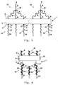
- reference number 1 is assigned to the flow divider according to the invention.
- a tubular expansion tank 2 made of stainless steel is provided on the gas inlet side 3 of the flow divider 1, the expansion tank 2 has bores arranged at a distance of approximately 15 cm from one another and provided with connecting pieces 4. (The lower edge of the connecting piece 4 facing the expansion vessel 2 corresponds approximately to the respective bore).
- Each connecting piece 4 is connected via a connecting hose 5 made of polytetrafluoroethylene (PTFE) to a mass flow controller 6 for an SiCl 4 gas flow and to a mass flow controller 7 for an oxygen gas flow.
- the direction arrows 8 indicate the direction of flow of the gases mentioned.
- gas inlet 15 are the components 4 assigned to each gas duct on the gas inlet side 3; 5; 6; 7 and the corresponding gas inlet opening of the expansion tank 2 as a whole.
- the expansion tank 2 by means of the mass flow controller 6; 7 predetermined partial flow of the total gas flow introduced into the expansion tank 2.
- the expansion tank 2 On the gas outlet side 9 of the flow divider 1, the expansion tank 2 has the same number of Holes on as on the gas inlet side 3. At the holes are with an external thread provided pipe socket 10 welded. (The upper edge facing the expansion tank 2 the pipe socket 10 approximately coincides with the respective bore).
- a sleeve-shaped gas outlet nozzle 11 In each of the pipe sockets 10 is a sleeve-shaped gas outlet nozzle 11, which by means of a in the external thread of the Pipe socket 10 engaging union nut 12 is connected to this gas-tight, arranged.
- the gas outlet nozzle 11 is made of stainless steel. Your inside diameter is on Accurately worked +/- 5 ⁇ m.
- the gas outlet nozzles 11 are each of the same length of PTFE tubing 13 gas-tight connected to a built-in burner 14 for quartz glass soot. With gas line 16 are subsequently assigned to each gas duct on the gas outlet side 9 Components 10; 11; 12; 13 overall designated.
- the built-in burner 14 is made of quartz glass. Its with the PTFE tube 13 connected The center nozzle has an internal diameter which is approximately 30% larger than that of the gas outlet nozzle 11.
- everybody Body burner 14 has additional connections in FIG. 1 (not shown) for the others Burner gases such as hydrogen or oxygen.
- the mode of operation of the flow divider according to the invention is explained in more detail below with reference to FIG. 1.
- SiCl 4 is evaporated and together with oxygen as a carrier gas via the mass flow controller 6; 7 supplied to the expansion tank 4 in a regulated flow rate.
- the gases are supplied via a plurality of gas inlets 15 axially evenly distributed over the gas inlet side 3 of the flow divider 1.
- the gas flows flowing into the expansion vessel 2 via the gas inlets 15 are approximately of the same size. Any differences in the gas flows can compensate in the expansion tank 2. There are therefore only slight pressure differences within the expansion tank 2.
- the same gas pressure is therefore present at all of the pipe sockets 10 which are evenly spaced from one another on the gas outlet side 9. Since the inner diameter of the pipe socket 10 is larger than the inner diameter of the gas outlet nozzles 11 inserted into it, the same gas pressure is also present at all gas outlet nozzles 11.
- the inner diameter of the gas outlet nozzles 11 is in each case the narrowest point of the gas lines 16, which connect the expansion vessel 2 to a separating burner 14 in each case.
- the gas outlet nozzles 11 therefore represent the maximum flow resistance in the gas lines 16; the maximum pressure drop occurs at them.
- the inner diameter of the gas outlet nozzles 11 are the same and worked very precisely.
- the flow resistances for all gas lines 16 are the same, and the gas flows in all gas lines 16 are approximately the same after leaving the gas outlet nozzles 11.
- the flow resistances which can be set very precisely from stainless steel, therefore allow good reproducibility of the gas flows to be set and thus a high dimensional accuracy of the soot bodies to be produced.
- the flow divider 1 Due to the structural separation of the flow resistances in the form of the gas outlet nozzles 11 from the deposition burners 14 is also an outgoing from the deposition burners 14 Contamination and an associated change in flow resistance avoided.
- the flow divider 1 according to the invention is therefore also characterized by a temporal Consistency of the flow resistances, which result in an axial homogeneity of the Soot body precipitates. This effect is compared to that from the prior art Technology known flow divider is further reinforced by the fact that fluctuations in the gas supply as a result faulty or drifting mass flow controller 6; 7 due to the large number of gas inlets 16 can be compensated.
- FIGS. 2 to 4 relate to identical or equivalent components or components of the flow divider 1 as they are based on the embodiment in Figure 1 for the identical reference numerals are explained.
- a flow divider 1 is shown in FIG the flow divider 1 according to Figure 1, the number of gas inlets 15 is approximately halved. There thus only half the number of mass flow controllers 6; 7 is required is the embodiment according to Figure 2 inexpensive.
- the disadvantage is that the distance of 30 cm of the gas inlets 15 from each other, depending on the total gas flow introduced Can set pressure differences within the expansion tank 2.
- the essentially rectangular expansion vessel 2 has a hemispherical extension 17 to which a plurality of gas lines 16 are connected. Due to the spherical shape, an optimally homogeneous pressure distribution is ensured on the inner walls of the extension 17, and thus on the gas outlet nozzles 11 arranged there.
- 2 heating coils 19 are attached to the outer wall of the expansion tank, by means of which the interior of the expansion tank 2 can be kept at a temperature of at least 60 ° C. For the same reason, the gas inlets 15 and the gas lines 16 are wrapped with heating tapes 20.
Landscapes
- Chemical & Material Sciences (AREA)
- Engineering & Computer Science (AREA)
- Organic Chemistry (AREA)
- Chemical Kinetics & Catalysis (AREA)
- Materials Engineering (AREA)
- General Chemical & Material Sciences (AREA)
- Manufacturing & Machinery (AREA)
- Life Sciences & Earth Sciences (AREA)
- Metallurgy (AREA)
- General Life Sciences & Earth Sciences (AREA)
- Geochemistry & Mineralogy (AREA)
- Mechanical Engineering (AREA)
- Glass Melting And Manufacturing (AREA)
- Servomotors (AREA)
- Pipeline Systems (AREA)
- Manufacture, Treatment Of Glass Fibers (AREA)
Claims (9)
- Dispositif pour la répartition d'un courant de gaz en plusieurs courants partiels de gaz, comprenant une chambre de compensation (2) qui présente pour le courant de gaz une admission de gaz (15) munie de plusieurs orifices d'admission de gaz (4) et pour les courants partiels de gaz plusieurs orifices de sortie de gaz (10) reliés par une conduite de gaz (16) à un poste de consommation de gaz (14), la résistance hydraulique maximale (11) étant prévue vu dans le sens d'écoulement (8) des courants partiels de gaz dans la zone aval des orifices de sortie de gaz (10) pour chaque courant partiel de gaz, caractérisé en ce que la résistance hydraulique maximale (11) est prévue pour chaque courant partiel de gaz dans la conduite de gaz (16) entre l'orifice de sortie de gaz (10) et le poste de consommation de gaz (14) et en ce que les résistances hydrauliques (11) interviennent de manière interchangeable dans les conduites de gaz respectives (16).
- Dispositif selon la revendication 1, caractérisé en ce que les résistances hydrauliques (11) sont respectivement conçues sous forme d'un composant métallique.
- Dispositif selon l'une des revendications précédentes, caractérisé en ce que la chambre de compensation (2) a une forme cylindrique et en ce que les orifices d'admission de gaz (4) sont répartis régulièrement dans le sens longitudinal axial de la chambre de compensation (2), vu d'un point de vue axial.
- Dispositif selon l'une des revendications précédentes, caractérisé en ce que le nombre des orifices d'admission de gaz (4) concorde avec le nombre des postes de consommation (14) et/ou avec le nombre des orifices de sortie de gaz (10).
- Dispositif selon l'une des revendications précédentes, caractérisé en ce que chaque orifice d'admission de gaz (4) est au moins associé à un orifice de sortie de gaz (10) et en ce que la distance respective entre un orifice d'admission de gaz (4) et l'orifice de sortie de gaz (10) qui lui est associé ou les orifices de sortie de gaz (10) qui lui sont associés est approximativement identique.
- Dispositif selon l'une des revendications précédentes, caractérisé en ce que la chambre de compensation (2) peut être munie d'un chauffage.
- Dispositif selon l'une des revendications précédentes, caractérisé en ce que la chambre de compensation (2) est de forme cylindrique et en ce que la distance entre les orifices d'admission voisins (4) est comprise entre 10 cm et 50 cm.
- Dispositif selon l'une des revendications précédentes, caractérisé en ce que plusieurs courants de gaz partiels réglables individuellement les uns des autres peuvent être amenés en même temps par chaque orifice d'admission de gaz (4) à la chambre de compensation (2).
- Dispositif selon l'une des revendications précédentes, caractérisé en ce qu'il est prévu un nombre identique de chambres de compensation (2) à celui des divers courants de gaz à amener respectivement aux postes de consommation de gaz (14).
Applications Claiming Priority (2)
| Application Number | Priority Date | Filing Date | Title |
|---|---|---|---|
| DE19501733A DE19501733C1 (de) | 1995-01-20 | 1995-01-20 | Vorrichtung zur Aufteilung eines Gasstromes in mehrere Teilgasströme |
| DE19501733 | 1995-01-20 |
Publications (2)
| Publication Number | Publication Date |
|---|---|
| EP0722909A1 EP0722909A1 (fr) | 1996-07-24 |
| EP0722909B1 true EP0722909B1 (fr) | 1999-03-10 |
Family
ID=7751978
Family Applications (1)
| Application Number | Title | Priority Date | Filing Date |
|---|---|---|---|
| EP95118914A Expired - Lifetime EP0722909B1 (fr) | 1995-01-20 | 1995-12-01 | Dispositif pour la répartition d'un courant gazeux en plusieurs courants partials gazeux |
Country Status (4)
| Country | Link |
|---|---|
| US (1) | US6152166A (fr) |
| EP (1) | EP0722909B1 (fr) |
| JP (1) | JP3576300B2 (fr) |
| DE (1) | DE19501733C1 (fr) |
Families Citing this family (9)
| Publication number | Priority date | Publication date | Assignee | Title |
|---|---|---|---|---|
| DE10025176A1 (de) * | 2000-05-24 | 2001-12-06 | Heraeus Quarzglas | Verfahren für die Herstellung einer optischen Faser und Vorform für eine optische Faser |
| AU2003210420A1 (en) * | 2002-03-22 | 2003-10-08 | Heraeus Tenevo Ag | Method for producing an optical fiber and optical fiber |
| JP5090646B2 (ja) * | 2005-12-27 | 2012-12-05 | 信越石英株式会社 | バーナー装置 |
| JP4809401B2 (ja) * | 2008-07-18 | 2011-11-09 | 信越化学工業株式会社 | 石英ガラスの製造方法及び装置 |
| DE102011119374A1 (de) | 2011-11-25 | 2013-05-29 | Heraeus Quarzglas Gmbh & Co. Kg | Verfahren zur Herstellung von synthetischem Quarzglas |
| DE102011119339A1 (de) | 2011-11-25 | 2013-05-29 | Heraeus Quarzglas Gmbh & Co. Kg | Zerstäubungsverfahren zur Herstellung von synthetischem Quarzglas |
| DE102011119341A1 (de) | 2011-11-25 | 2013-05-29 | Heraeus Quarzglas Gmbh & Co. Kg | Verfahren zur Herstellung von synthetischem Quarzglas nach der Sootmethode |
| DE102011119373A1 (de) | 2011-11-25 | 2013-05-29 | Heraeus Quarzglas Gmbh & Co. Kg | Verfahren zur Herstellung von synthetischem Quarzglas |
| CN107207319B (zh) | 2015-01-08 | 2020-10-09 | 古河电气工业株式会社 | 气体分流装置及使用气体分流装置的玻璃微粒堆积体的制造方法 |
Family Cites Families (13)
| Publication number | Priority date | Publication date | Assignee | Title |
|---|---|---|---|---|
| US3785402A (en) * | 1972-07-27 | 1974-01-15 | Exxon Production Research Co | Removable tubular insert for reducing erosion in headers |
| US4263939A (en) * | 1979-04-27 | 1981-04-28 | Modern Engineering Company, Inc. | Single stage regulator with surge reducing valve |
| JPS5980325A (ja) * | 1982-10-29 | 1984-05-09 | Fujitsu Ltd | 反応ガス分配方法 |
| JPH0686300B2 (ja) * | 1987-07-01 | 1994-11-02 | 信越石英株式会社 | すす状シリカ体及びその製造方法 |
| US5035221A (en) * | 1989-01-11 | 1991-07-30 | Martin Tiby M | High pressure electronic common-rail fuel injection system for diesel engines |
| US5056597A (en) * | 1989-07-27 | 1991-10-15 | Chevron Research And Technology Company | Method for improving the steam splits in a multiple steam injection process using multiple steam headers |
| US5152819A (en) * | 1990-08-16 | 1992-10-06 | Corning Incorporated | Method of making fused silica |
| US5116400A (en) * | 1990-09-20 | 1992-05-26 | Corning Incorporated | Apparatus for forming a porous glass preform |
| JP2763222B2 (ja) * | 1991-12-13 | 1998-06-11 | 三菱電機株式会社 | 化学気相成長方法ならびにそのための化学気相成長処理システムおよび化学気相成長装置 |
| US5368062A (en) * | 1992-01-29 | 1994-11-29 | Kabushiki Kaisha Toshiba | Gas supplying system and gas supplying apparatus |
| US5334352A (en) * | 1992-09-23 | 1994-08-02 | Icn Biomedicals, Inc. | Manifold construction |
| WO1994015707A2 (fr) * | 1993-01-15 | 1994-07-21 | Aixtron Gmbh | Dispositif permettant a au moins un gaz utilise dans un processus industriel d'entrer simultanement dans une pluralite de chambres de reaction |
| CH687258A5 (de) * | 1993-04-22 | 1996-10-31 | Balzers Hochvakuum | Gaseinlassanordnung. |
-
1995
- 1995-01-20 DE DE19501733A patent/DE19501733C1/de not_active Expired - Fee Related
- 1995-12-01 EP EP95118914A patent/EP0722909B1/fr not_active Expired - Lifetime
-
1996
- 1996-01-16 US US08/587,359 patent/US6152166A/en not_active Expired - Lifetime
- 1996-01-22 JP JP00848896A patent/JP3576300B2/ja not_active Expired - Lifetime
Also Published As
| Publication number | Publication date |
|---|---|
| JPH08284904A (ja) | 1996-11-01 |
| EP0722909A1 (fr) | 1996-07-24 |
| DE19501733C1 (de) | 1996-05-15 |
| JP3576300B2 (ja) | 2004-10-13 |
| US6152166A (en) | 2000-11-28 |
Similar Documents
| Publication | Publication Date | Title |
|---|---|---|
| DE10300029B4 (de) | Massenstrom-Verhältnis-System und -Verfahren | |
| DE69227575T2 (de) | Programmierbarer Multizonen-Gasinjektor für eine Anlage zur Behandlung von einzelnen Halbleiterscheiben | |
| EP0001391B1 (fr) | Dispositif de refroidissement des profilés continus, en forme d'un tube à double-paroi | |
| DE19501733C1 (de) | Vorrichtung zur Aufteilung eines Gasstromes in mehrere Teilgasströme | |
| DE3814917C2 (fr) | ||
| DE102011011207A1 (de) | Brenner zum gleichmäßigen Erwärmen eines langen Ofens | |
| EP0513414B1 (fr) | Dispositif à tuyères pour la commande d'un courant de gaz | |
| DE69620736T2 (de) | WIRBELBETT mit gleichmässiger Wärmeverteilung und mehrportiger Dute | |
| DE69119755T2 (de) | Verbesserte glühfilament-cvd-anlage | |
| DE2507261A1 (de) | Narkosemittelverdunster mit einem der verdunsterkammer parallelgeschalteten bypass | |
| DE19960333C2 (de) | Vorrichtung zum Herstellen eines Gasgemisches und deren Verwendung | |
| EP4669785A1 (fr) | Admission de gaz pour réacteur cvd | |
| EP4089357B1 (fr) | Echangeur de chaleur | |
| DE4436908A1 (de) | Düse für eine Verbrennungsvorrichtung | |
| WO2018086759A1 (fr) | Procédé de changement de température d'un fluide au moyen d'un échangeur de chaleur tubulaire et échangeur de chaleur tubulaire | |
| EP1466716B1 (fr) | Installation de distribution pour composition plastique plastifiée | |
| DE102013204309A1 (de) | Strahlbrenner | |
| AT527036B1 (de) | Gasmischsystem für ein Brennstoffzellensystem | |
| DE1112025B (de) | Vorrichtung zum Konstanthalten der Zusammensetzung einer Mischung von Luft und brennbarem Gas | |
| DE102006051044A1 (de) | Verfahren und Einrichtung zum Betreiben einer Brennschneidmaschine zum Brennschneiden von Gießsträngen und Werkstücken | |
| EP2350548A1 (fr) | Dispositif de transfert de chaleur et de purification d'air et procédé pour transférer de la chaleur | |
| EP3409812A1 (fr) | Système d'alimentation en gaz et procédé d'alimentation en gaz | |
| DE102004004858A1 (de) | Vorrichtung zum Beschichten von Substratscheiben, Gaszufuhreinrichtung und Verfahren zu ihrer Herstellung | |
| DE19858831C2 (de) | Quarzschmelzbrenner | |
| DE102022110733A1 (de) | Mischungsvorrichtung für einen primären Fluidstrom in einem ersten Rohr mit mindestens einem sekundären Fluidstrom, ein Verfahren zur Mischung und ein Flugzeugtriebwerk |
Legal Events
| Date | Code | Title | Description |
|---|---|---|---|
| PUAI | Public reference made under article 153(3) epc to a published international application that has entered the european phase |
Free format text: ORIGINAL CODE: 0009012 |
|
| 17P | Request for examination filed |
Effective date: 19951220 |
|
| AK | Designated contracting states |
Kind code of ref document: A1 Designated state(s): FR GB |
|
| 17Q | First examination report despatched |
Effective date: 19970214 |
|
| GRAG | Despatch of communication of intention to grant |
Free format text: ORIGINAL CODE: EPIDOS AGRA |
|
| GRAG | Despatch of communication of intention to grant |
Free format text: ORIGINAL CODE: EPIDOS AGRA |
|
| GRAH | Despatch of communication of intention to grant a patent |
Free format text: ORIGINAL CODE: EPIDOS IGRA |
|
| RBV | Designated contracting states (corrected) |
Designated state(s): FR GB |
|
| REG | Reference to a national code |
Ref country code: DE Ref legal event code: 8566 |
|
| GRAH | Despatch of communication of intention to grant a patent |
Free format text: ORIGINAL CODE: EPIDOS IGRA |
|
| GRAA | (expected) grant |
Free format text: ORIGINAL CODE: 0009210 |
|
| AK | Designated contracting states |
Kind code of ref document: B1 Designated state(s): FR GB |
|
| GBT | Gb: translation of ep patent filed (gb section 77(6)(a)/1977) |
Effective date: 19990310 |
|
| ET | Fr: translation filed | ||
| PLBE | No opposition filed within time limit |
Free format text: ORIGINAL CODE: 0009261 |
|
| STAA | Information on the status of an ep patent application or granted ep patent |
Free format text: STATUS: NO OPPOSITION FILED WITHIN TIME LIMIT |
|
| 26N | No opposition filed | ||
| REG | Reference to a national code |
Ref country code: GB Ref legal event code: IF02 |
|
| PGFP | Annual fee paid to national office [announced via postgrant information from national office to epo] |
Ref country code: GB Payment date: 20071218 Year of fee payment: 13 |
|
| PGFP | Annual fee paid to national office [announced via postgrant information from national office to epo] |
Ref country code: FR Payment date: 20071217 Year of fee payment: 13 |
|
| GBPC | Gb: european patent ceased through non-payment of renewal fee |
Effective date: 20081201 |
|
| REG | Reference to a national code |
Ref country code: FR Ref legal event code: ST Effective date: 20090831 |
|
| PG25 | Lapsed in a contracting state [announced via postgrant information from national office to epo] |
Ref country code: GB Free format text: LAPSE BECAUSE OF NON-PAYMENT OF DUE FEES Effective date: 20081201 |
|
| PG25 | Lapsed in a contracting state [announced via postgrant information from national office to epo] |
Ref country code: FR Free format text: LAPSE BECAUSE OF NON-PAYMENT OF DUE FEES Effective date: 20081231 |