EP0722871B1 - Railroad vehicle control assembly, and railroad vehicle equipped therewith - Google Patents
Railroad vehicle control assembly, and railroad vehicle equipped therewith Download PDFInfo
- Publication number
- EP0722871B1 EP0722871B1 EP96100571A EP96100571A EP0722871B1 EP 0722871 B1 EP0722871 B1 EP 0722871B1 EP 96100571 A EP96100571 A EP 96100571A EP 96100571 A EP96100571 A EP 96100571A EP 0722871 B1 EP0722871 B1 EP 0722871B1
- Authority
- EP
- European Patent Office
- Prior art keywords
- control
- operating
- assembly
- brake pipe
- cab
- Prior art date
- Legal status (The legal status is an assumption and is not a legal conclusion. Google has not performed a legal analysis and makes no representation as to the accuracy of the status listed.)
- Expired - Lifetime
Links
Images
Classifications
-
- B—PERFORMING OPERATIONS; TRANSPORTING
- B61—RAILWAYS
- B61C—LOCOMOTIVES; MOTOR RAILCARS
- B61C17/00—Arrangement or disposition of parts; Details or accessories not otherwise provided for; Use of control gear and control systems
- B61C17/04—Arrangement or disposition of driving cabins, footplates or engine rooms; Ventilation thereof
Definitions
- the present invention relates to a control assembly for a railroad vehicle, in particular an electric locomotive.
- Known locomotives are controlled from inside a driver's cab comprising a control console, in turn comprising an operating control or selector, which is operated manually by the driver to select various operating conditions, e.g. normal running, slow brake, fast brake, overload brake, isolation, etc.
- the location of the operating control on the console varies according to the type of locomotive, and more specifically, according to the country in which the locomotive is operated.
- the driver is stationed on the left-hand side of the cab and, with the left hand, operates a control comprising a drum rotating about a substantially vertical axis and controlled by a substantially horizontal lever.
- the driver is likewise stationed on the left-hand side of the cab, but, with the right hand, operates a control located centrally on the console, and comprising a control lever which is rotated to various operating positions about a horizontal axis.
- the console also comprises an emergency fast-brake button which is used in place of the normal operating control.
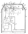
- Number 1 in the accompanying drawing indicates a locomotive comprising a driver's cab 2, in turn comprising a front wall 3 and two lateral walls 4, 5.
- Cab 2 houses a control console 6 presenting an operating station 7 and an additional station 8 located side by side and facing front wall 3.
- Locomotive 2 also comprises a brake control assembly 9, in turn comprising a control system 10 of the type described and illustrated in Italian Patent Applications n. 67282-A/85 and n. 67097-A/87 (& EP-A-0 278 928) filed respectively on 22/03/1985 and 13/02/1987 by the present Applicant, and to which full reference is made herein in the interest of full disclosure.
- control system 10 comprises a main air pipe 11 connected to a compressed air source (not shown); and an air brake pipe 12 connected by a number of distributors (not shown) to a corresponding number of brake cylinders (not shown).
- System 10 also comprises a known self-regulating device 12a connected to main pipe 11 and brake pipe 12 to supply and discharge pipe 12, and which in turn comprises a known electropneumatic circuit 12b, and an operating control 13 inside cab 2, adjacent to lateral wall 4, and associated with station 7. More specifically, control 13 is connected to electropneumatic circuit 12b, and comprises a drum 14 rotating about a substantially vertical axis 15, and an operating lever 16 for rotating drum 14 about axis 15 and selecting various operating conditions, such as normal running, slow brake, fast brake, isolation, etc.
- Device 12a also comprises a known fast exhaust valve 17 (shown schematically) operated by control 13 and connected at the inlet to brake pipe 12; and a known isolating valve 18 switchable by control 13 to disconnect brake pipe 12 from main pipe 11.
- isolating valve 18 is replaced by an isolating solenoid valve 19 preferably activated in known manner by a known electronic control unit 20.
- Unit 20 forms part of device 12a, and provides for activating solenoid valve 19 in known manner, and more specifically in response to a signal supplied to it in known manner by control 13 when set to the isolating position.
- isolating solenoid valve 19 is operated directly by control 13.
- assembly 9 also comprises a further operating control 21 located centrally, substantially between stations 7 and 8, and associated with station 7.
- Control 21 performs the same functions as control 13, from which it differs by comprising a drum 22 rotating about an axis 23 perpendicular to axis 15, and an operating lever 24 for rotating drum 22 about axis 23 and selecting various operating positions.
- Assembly 9 also comprises a further mechanically operated fast exhaust valve 25, which is operated by control 21 when lever 24 is set to the "fast” position, and is connected to brake pipe 12 in parallel with valve 17.
- Assembly 9 also comprises an operating control 26 associated with station 8, located adjacent to lateral wall 5, and substantially similar to control 21.
- Control 26 operates a further mechanically operated fast exhaust valve 27 forming part of assembly 9 and connected at the inlet to brake pipe 12 in parallel with valves 17 and 25.
- Controls 13, 21 and 26 present respective known signal generating devices 28, each connected electrically to a respective input of a known switching unit 29, the output of which is connected electrically to unit 20. More specifically, unit 29 provides for selectively activating controls 13, 21 and 26, and for supplying unit 20 with the control signals from the generating device 28 of the activated control.
- Assembly 9 also comprises one or more further mechanically operated fast exhaust valves 30 (only one shown), each operated manually by the driver by means of a respective pushbutton 31 on console 6, each connected at the inlet to brake pipe 12 between and in parallel with valves 17 and 25, and each provided with a respective known signal generator 32 connected electrically to unit 20.
- lever 16 may be rotated about axis 15 to supply unit 20, via unit 29, with a succession of electric signals, in response to which, unit 20 sets circuit 12b to a corresponding number of different operating positions; and control 13 may also be used for fast braking by discharging brake pipe 12 via valve 17, and for disconnecting brake pipe 12 from main pipe 11 by means of solenoid valve 19 or valve 18.
- control 21 When changing drivers at a border crossing, control 21 may be operated in place of control 13 from the same station 7, by simply enabling control 21 by rotating lever 24 to a "recognition or enabling" position in which respective device 28 supplies unit 29 with a switching signal, in response to which unit 29 disables control 13 and enables control 21. More specifically, with known switching units 29 commonly used on trains, lever 24 must be so set as to select a greater braking force than that provided for by control 13, in which case, unit 29 disconnects control 13 from unit 20, and connects unit 20 to control 21, the lever 24 of which may then be used for performing the same operations as with control 13.
- brake pipe 12 may be disconnected from main pipe 11, pipes 11 and 12 may be connected to each other by switching solenoid valve 19, or brake pipe 12 may be discharged rapidly by activating valve 25.
- control 21 and enable control 26 or control 13 to respectively control the brake function from station 8 using a different control, or once more from station 7.
- assembly 9 therefore provides for fast, troublefree changeover of the driver, and in particular for eliminating any uneasiness on the part of the new driver.
- Equipping console 6 with a number of differently designed controls, and the particular location of the controls inside cab 2, provide for achieving optimum working conditions, in particular by creating a station 7 familiar to both drivers.
- each driver operates a control that is not only of the same design as that to which he is accustomed, but also occupies the same position in cab 2, and more specifically on console 6.
- assembly 9 therefore provides for greatly reducing running cost and downtime by eliminating the need to change the locomotive at border crossings.
- control 26 and valve 30 may be dispensed with; and at least one of controls 13, 21, 26 may be replaced by a control differing in design from that described by way of example.
Landscapes
- Engineering & Computer Science (AREA)
- Automation & Control Theory (AREA)
- Transportation (AREA)
- Mechanical Engineering (AREA)
- Electric Propulsion And Braking For Vehicles (AREA)
- Train Traffic Observation, Control, And Security (AREA)
- Regulating Braking Force (AREA)
- Braking Systems And Boosters (AREA)
- Automatic Cycles, And Cycles In General (AREA)
Applications Claiming Priority (2)
| Application Number | Priority Date | Filing Date | Title |
|---|---|---|---|
| ITTO950017U | 1995-01-20 | ||
| IT1995TO000017U IT235766Y1 (it) | 1995-01-20 | 1995-01-20 | Gruppo di comando per un veicolo ferroviario, e veicolo ferroviarioprovvisto di tale gruppo. |
Publications (2)
| Publication Number | Publication Date |
|---|---|
| EP0722871A1 EP0722871A1 (en) | 1996-07-24 |
| EP0722871B1 true EP0722871B1 (en) | 1999-07-21 |
Family
ID=11413056
Family Applications (1)
| Application Number | Title | Priority Date | Filing Date |
|---|---|---|---|
| EP96100571A Expired - Lifetime EP0722871B1 (en) | 1995-01-20 | 1996-01-16 | Railroad vehicle control assembly, and railroad vehicle equipped therewith |
Country Status (5)
| Country | Link |
|---|---|
| EP (1) | EP0722871B1 (it) |
| AT (1) | ATE182295T1 (it) |
| DE (1) | DE69603293T2 (it) |
| ES (1) | ES2135795T3 (it) |
| IT (1) | IT235766Y1 (it) |
Citations (1)
| Publication number | Priority date | Publication date | Assignee | Title |
|---|---|---|---|---|
| EP0278928A1 (en) * | 1987-02-13 | 1988-08-17 | WABCO WESTINGHOUSE COMPAGNIA FRENI S.p.A. | System for controlling the automatic brakes of a railway vehicle, by means of electrical signal transmission |
Family Cites Families (2)
| Publication number | Priority date | Publication date | Assignee | Title |
|---|---|---|---|---|
| CH171225A (de) * | 1933-09-07 | 1934-08-15 | Oerlikon Maschf | Triebfahrzeug mit einem Führerhaus für beide Fahrtrichtungen. |
| US5335750A (en) * | 1992-06-11 | 1994-08-09 | Sauer Inc. | Dual mode transmission control |
-
1995
- 1995-01-20 IT IT1995TO000017U patent/IT235766Y1/it active IP Right Grant
-
1996
- 1996-01-16 EP EP96100571A patent/EP0722871B1/en not_active Expired - Lifetime
- 1996-01-16 DE DE69603293T patent/DE69603293T2/de not_active Expired - Fee Related
- 1996-01-16 AT AT96100571T patent/ATE182295T1/de active
- 1996-01-16 ES ES96100571T patent/ES2135795T3/es not_active Expired - Lifetime
Patent Citations (1)
| Publication number | Priority date | Publication date | Assignee | Title |
|---|---|---|---|---|
| EP0278928A1 (en) * | 1987-02-13 | 1988-08-17 | WABCO WESTINGHOUSE COMPAGNIA FRENI S.p.A. | System for controlling the automatic brakes of a railway vehicle, by means of electrical signal transmission |
Also Published As
| Publication number | Publication date |
|---|---|
| ATE182295T1 (de) | 1999-08-15 |
| ITTO950017U1 (it) | 1996-07-20 |
| ES2135795T3 (es) | 1999-11-01 |
| IT235766Y1 (it) | 2000-07-18 |
| ITTO950017V0 (it) | 1995-01-20 |
| DE69603293T2 (de) | 2000-01-05 |
| EP0722871A1 (en) | 1996-07-24 |
| DE69603293D1 (de) | 1999-08-26 |
Similar Documents
| Publication | Publication Date | Title |
|---|---|---|
| US20020096840A1 (en) | Control system for lifting and lowering the body of an air-suspended vehicle incliding level control | |
| SE455403B (sv) | Bromssystem for fordonstag med en slepvagnsstyrventil, som er styrbar fran atminstone tva dragfordonsferdbromskretsar | |
| AU6806498A (en) | Method and apparatus for controlling electro-pneumatic brakes on trains using an existing locomotive electronic air brakes | |
| EP0404690B1 (en) | Pneumatic circuit for wheel mounted shovel | |
| EP3822134B1 (en) | Brake system for a motor vehicle and trailer control module | |
| EP0722871B1 (en) | Railroad vehicle control assembly, and railroad vehicle equipped therewith | |
| EP1138570B1 (en) | A railway train braking control and communication system | |
| US4679863A (en) | Emergency brake command read-convert device for railway train having cars with pneumatic and cars with electrical brake control | |
| US3738680A (en) | Pneumatic suspension system for vehicles | |
| JPH07501767A (ja) | 後端にトランスミッション制御部を有する後部排出型コンクリートミキサー | |
| JPH0316869A (ja) | ブレーキ弁装置 | |
| US4971399A (en) | System for assuring recharge of brake pipe pressure in holding position of locomotive brake valve | |
| RU118928U1 (ru) | Блок тормозного оборудования | |
| RU2765170C1 (ru) | Система управления приводом рельсового транспортного средства | |
| US7226135B2 (en) | Braking system for a self-powered rail vehicle provided with an anti-slip device | |
| JP3342554B2 (ja) | 空電併用連結器の自動解結装置 | |
| RU2110424C1 (ru) | Тормозная система железнодорожного транспортного средства | |
| KR0143616B1 (ko) | 전동차의 브레이크제어시스템 | |
| RU2352482C1 (ru) | Комплекс тормозного оборудования локомотива | |
| JP2555206B2 (ja) | 車両の駐車ブレーキ装置 | |
| US1761419A (en) | Deenergizing circuit for coupled cars | |
| JP2516126Y2 (ja) | 旋回フラッシャ装置 | |
| RU2112673C1 (ru) | Тормозная система железнодорожного транспортного средства | |
| ATE130281T1 (de) | System zur unverwechselbaren anschaltung von versorgungsschläuchen an einen tankwagen. | |
| JP3247019B2 (ja) | 自走式建設廃材破砕機の警報装置 |
Legal Events
| Date | Code | Title | Description |
|---|---|---|---|
| PUAI | Public reference made under article 153(3) epc to a published international application that has entered the european phase |
Free format text: ORIGINAL CODE: 0009012 |
|
| AK | Designated contracting states |
Kind code of ref document: A1 Designated state(s): AT BE CH DE ES FR GB LI NL |
|
| 17P | Request for examination filed |
Effective date: 19961116 |
|
| 17Q | First examination report despatched |
Effective date: 19980403 |
|
| GRAG | Despatch of communication of intention to grant |
Free format text: ORIGINAL CODE: EPIDOS AGRA |
|
| GRAG | Despatch of communication of intention to grant |
Free format text: ORIGINAL CODE: EPIDOS AGRA |
|
| GRAH | Despatch of communication of intention to grant a patent |
Free format text: ORIGINAL CODE: EPIDOS IGRA |
|
| GRAH | Despatch of communication of intention to grant a patent |
Free format text: ORIGINAL CODE: EPIDOS IGRA |
|
| GRAA | (expected) grant |
Free format text: ORIGINAL CODE: 0009210 |
|
| AK | Designated contracting states |
Kind code of ref document: B1 Designated state(s): AT BE CH DE ES FR GB LI NL |
|
| REF | Corresponds to: |
Ref document number: 182295 Country of ref document: AT Date of ref document: 19990815 Kind code of ref document: T |
|
| REG | Reference to a national code |
Ref country code: CH Ref legal event code: EP |
|
| REG | Reference to a national code |
Ref country code: CH Ref legal event code: NV Representative=s name: ISLER & PEDRAZZINI AG |
|
| REF | Corresponds to: |
Ref document number: 69603293 Country of ref document: DE Date of ref document: 19990826 |
|
| ET | Fr: translation filed | ||
| REG | Reference to a national code |
Ref country code: ES Ref legal event code: FG2A Ref document number: 2135795 Country of ref document: ES Kind code of ref document: T3 |
|
| PG25 | Lapsed in a contracting state [announced via postgrant information from national office to epo] |
Ref country code: GB Free format text: LAPSE BECAUSE OF NON-PAYMENT OF DUE FEES Effective date: 20000116 |
|
| PG25 | Lapsed in a contracting state [announced via postgrant information from national office to epo] |
Ref country code: BE Free format text: LAPSE BECAUSE OF NON-PAYMENT OF DUE FEES Effective date: 20000131 |
|
| PLBE | No opposition filed within time limit |
Free format text: ORIGINAL CODE: 0009261 |
|
| STAA | Information on the status of an ep patent application or granted ep patent |
Free format text: STATUS: NO OPPOSITION FILED WITHIN TIME LIMIT |
|
| 26N | No opposition filed | ||
| BERE | Be: lapsed |
Owner name: SAB WABCO S.P.A. Effective date: 20000131 |
|
| PG25 | Lapsed in a contracting state [announced via postgrant information from national office to epo] |
Ref country code: NL Free format text: LAPSE BECAUSE OF NON-PAYMENT OF DUE FEES Effective date: 20000801 |
|
| GBPC | Gb: european patent ceased through non-payment of renewal fee |
Effective date: 20000116 |
|
| NLV4 | Nl: lapsed or anulled due to non-payment of the annual fee |
Effective date: 20000801 |
|
| PGFP | Annual fee paid to national office [announced via postgrant information from national office to epo] |
Ref country code: FR Payment date: 20010112 Year of fee payment: 6 |
|
| PGFP | Annual fee paid to national office [announced via postgrant information from national office to epo] |
Ref country code: AT Payment date: 20010122 Year of fee payment: 6 |
|
| PGFP | Annual fee paid to national office [announced via postgrant information from national office to epo] |
Ref country code: ES Payment date: 20010124 Year of fee payment: 6 Ref country code: DE Payment date: 20010124 Year of fee payment: 6 |
|
| PGFP | Annual fee paid to national office [announced via postgrant information from national office to epo] |
Ref country code: CH Payment date: 20010131 Year of fee payment: 6 |
|
| PG25 | Lapsed in a contracting state [announced via postgrant information from national office to epo] |
Ref country code: AT Free format text: LAPSE BECAUSE OF NON-PAYMENT OF DUE FEES Effective date: 20020116 |
|
| PG25 | Lapsed in a contracting state [announced via postgrant information from national office to epo] |
Ref country code: ES Free format text: LAPSE BECAUSE OF NON-PAYMENT OF DUE FEES Effective date: 20020117 |
|
| PG25 | Lapsed in a contracting state [announced via postgrant information from national office to epo] |
Ref country code: LI Free format text: LAPSE BECAUSE OF NON-PAYMENT OF DUE FEES Effective date: 20020131 Ref country code: CH Free format text: LAPSE BECAUSE OF NON-PAYMENT OF DUE FEES Effective date: 20020131 |
|
| PG25 | Lapsed in a contracting state [announced via postgrant information from national office to epo] |
Ref country code: DE Free format text: LAPSE BECAUSE OF NON-PAYMENT OF DUE FEES Effective date: 20020801 |
|
| REG | Reference to a national code |
Ref country code: CH Ref legal event code: PL |
|
| PG25 | Lapsed in a contracting state [announced via postgrant information from national office to epo] |
Ref country code: FR Free format text: LAPSE BECAUSE OF NON-PAYMENT OF DUE FEES Effective date: 20020930 |
|
| REG | Reference to a national code |
Ref country code: FR Ref legal event code: ST |
|
| REG | Reference to a national code |
Ref country code: ES Ref legal event code: FD2A Effective date: 20031122 |