EP0722654A1 - Appareil de traitement à bras porteur pour l'entretien des accotements routiers - Google Patents
Appareil de traitement à bras porteur pour l'entretien des accotements routiers Download PDFInfo
- Publication number
- EP0722654A1 EP0722654A1 EP96100849A EP96100849A EP0722654A1 EP 0722654 A1 EP0722654 A1 EP 0722654A1 EP 96100849 A EP96100849 A EP 96100849A EP 96100849 A EP96100849 A EP 96100849A EP 0722654 A1 EP0722654 A1 EP 0722654A1
- Authority
- EP
- European Patent Office
- Prior art keywords
- boom
- variable
- sensor arrangement
- control
- implement according
- Prior art date
- Legal status (The legal status is an assumption and is not a legal conclusion. Google has not performed a legal analysis and makes no representation as to the accuracy of the status listed.)
- Granted
Links
Images


Classifications
-
- E—FIXED CONSTRUCTIONS
- E02—HYDRAULIC ENGINEERING; FOUNDATIONS; SOIL SHIFTING
- E02F—DREDGING; SOIL-SHIFTING
- E02F5/00—Dredgers or soil-shifting machines for special purposes
- E02F5/28—Dredgers or soil-shifting machines for special purposes for cleaning watercourses or other ways
- E02F5/282—Dredgers or soil-shifting machines for special purposes for cleaning watercourses or other ways with rotating cutting or digging tools
-
- A—HUMAN NECESSITIES
- A01—AGRICULTURE; FORESTRY; ANIMAL HUSBANDRY; HUNTING; TRAPPING; FISHING
- A01D—HARVESTING; MOWING
- A01D34/00—Mowers; Mowing apparatus of harvesters
- A01D34/835—Mowers; Mowing apparatus of harvesters specially adapted for particular purposes
- A01D34/86—Mowers; Mowing apparatus of harvesters specially adapted for particular purposes for use on sloping ground, e.g. on embankments or in ditches
Definitions
- the invention relates to a mobile boom working device for entertainment work in the road area, in particular boom mower with a device for boom relief control according to changes in the resistance encountered by the working head, in particular the mowing head, depending on signals from a sensor arrangement, with separate lifting and lateral adjustment drives on the boom are provided for adjusting the boom in its vertical position and its lateral pivot position, and the lifting drive of the boom is under the control of the sensor signals in the context of a control circuit which, when the resistance encountered by the working head changes, the sensor arrangement supplies a disturbance variable to the control variable to which the control circuit reacts with a corresponding manipulated variable for correcting the height position of the boom by its lifting drive (according to the preamble of claim 1).
- Boom mowers of the design referred to here have been in successful use for many years and are particularly known from DE-PS 21 59 944. In their originally addressed form, they were equipped with a control for the height of the boom to be operated by the operator.
- the boom relief regulation addressed in the preamble of claim 1 is the subject of the older, not previously published patent application P 44 01 716.2.
- this older device in which the housing of the working head by a substantially parallel roller on the floor Terrain is supported and a proportional controllable pressure relief valve is assigned to influence the contact pressure of the unwind roller on the site of the lifting cylinder of the boom in the actuating device, it is provided that a displacement sensor arrangement with its probe in direct drive connection with the for sensing vertical movements of the unroll roller Unroll roller stands.
- the roller is suspended in the housing of the working head with its axis at the free end of a cantilever spring steel arrangement and the sensor probe is in tactile contact with the spring steel at the suspension point.
- the invention is based on the object of equipping a mobile boom working device of the type in question with a simple boom relief control which does not require sensor arrangements arranged on the working head and possibly also enables simple mounting of a rolling roller.
- the configuration of the sensor arrangement for the lateral pivot position as a switch cam and limit switch arrangement on the bogie of the boom is characterized by particular simplicity and robustness and can be implemented in a variety of ways in accordance with the respective structural conditions. Adjustment and adjustment options corresponding to the respective circumstances can also be implemented well.
- the sensor arrangement for the pivoting position of the bogie of the boom can, however, also be designed as a pressure sensor on the pivoting cylinder, and optical sensor arrangements with scanning position markings are also possible. Likewise also the design as a displacement sensor system in connection with the adjustment path when the pivot position of the bogie changes. Hydraulic swivel cylinders with built-in displacement sensors can also be used.
- the embankment mower can be returned to its normal position.
- such an arrangement does not allow a constant adjustment of the contact pressure of the working head in accordance with the constantly changing working conditions, such as are generated by changing terrain, changing driving speed, changes in the resistance of the processed material (thinner, thicker, wetter, drier grass) etc.
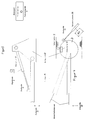
- Fig. 1 shows a plan view of a mobile boom working device with a working head in the form of a mowing head, which sits on a boom pivotable by means of a bogie.
- Fig. 2 shows such a device from behind with the mowing head arm extended sideways.
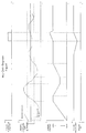
- Fig. 3. shows a schematic partial side view of a bogie with boom and lifting cylinder, wherein the mowing head is omitted from the boom and the influencing variables of a control circuit for the boom relief are indicated schematically.
- FIG. 4 shows a partial top view of the boom bogie according to FIG. 3 with a switch cam and limit switch arrangement for detecting changes in the pivoting angle in the bogie.
- FIG. 5 shows a block diagram of a boom relief control on the basis of a disturbance variable emitted by the switch cam and limit switch arrangement on the bogie as a sensor arrangement.
- Fig. 6 shows a schematic path-time diagram, in which are shown schematically with each other the temporal occurrence of a disturbance variable Z2 due to the lateral pivoting of the arm carrying the mowing head, the temporal deviations of the height position of the mowing head boom from the setpoint value W of the height position of the mowing head boom serving as a reference variable for the relief control circuit, the associated correcting manipulated variables Y1 for lifting and lowering the lifting cylinder of the boom and also the Correction manipulated variable Y2 for resetting the swivel cylinder to its normal position after a temporary deviation
- Fig. 1 shows a mobile boom working device for entertainment work in the road area in the form of a boom mower.
- a boom A On the carrier vehicle T is a boom A, which carries a mowing head M in a known manner.
- the boom A with the mowing head M carried by it can be adjusted to different swivel positions.
- the boom is pivoted out laterally essentially at a right angle, with a pivoting range of approximately 200 ° being provided on one or the other side of the road for processing.
- Fig. 2 also illustrates the bogie D for the boom A and also a lifting cylinder H by means of which the boom A with the mowing head M located thereon can be raised or lowered as required.
- Figure 2 also shows a rolling roller W with which the mowing head is supported on the site.
- a boom relief control is in the manner described in detail below provided that with its control circuit illustrated in FIG. 5 ensures that, on the basis of a set value W which can be set in the operating part 1 by means of a rotary potentiometer DP as the control variable of the control circuit, a constant readjustment of the height position of the boom A can take place based on the set value.
- the control circuit uses the signals from two different sensor arrangements.
- One sensor arrangement is formed by a pressure transducer U / P, which is provided on the lifting cylinder H of the boom A and determines the actual value of the pressure in the lifting cylinder, which is the controlled variable X of the control circuit in accordance with external influences, such as terrain inclinations encountered and also changes in accordance with the adjustments made by the control circuit for the necessary corrections of the pressure in the lifting cylinder H.
- the other sensor arrangement which influences the control circuit, responds to changes in the pivoting position of the boom A, as occurs when increased mowing resistance or the like occurs, because such increased resistance tends to cause the boom A and mowing head M a little against the direction of travel to drop back and thus change the swivel position.
- an arrangement of switch cams S and limit switch E is provided according to FIG. If the rotary position of the bogie D changes with the boom A located thereon, the limit switch E can run onto the switching cams S and emit a corresponding signal.
- sensor arrangements in the form of a pressure or displacement sensor on the pivoting cylinder SZ or also those with scanning of position markings can also be used Bogie or swivel cylinder as in Figure 4 schematically at "Alt.” indicated use.
- the control circuit for the boom relief shown in FIG. 5 is based on the actuator formed by the lifting cylinder H of the boom.
- a hydraulic pressure is formed in accordance with the hydraulic fluid supplied to him for adjusting the height position of the boom by means of a hydraulic control valve, the actual value of which is measured by means of the pressure sensor U / P as a sensor arrangement and is changed by the control circuit as control variable X if when the height of the boom changes due to external influences, a disturbance variable Z1 occurs.
- the actual value of the hydraulic pressure in the lifting cylinder is fed as control variable X to a comparator 2, to which the setpoint W set on the rotary potentiometer DP in the control unit is also fed as a control variable.
- the comparator determines the control difference Xd, which is fed to a controller 3 and is fed as an output signal YR to an addition point 9.
- This addition point 9 also receives a manipulated variable Y2, which is output by a ramp generator 6, which in turn receives input signals from the sensor arrangement consisting of limit switch E and switch cam S (in FIG. 5 in block 5) if there is a disturbance variable due to the changed pivoting position of the bogie G. Z2 occurs.
- a manipulated variable Y2 which is output by a ramp generator 6, which in turn receives input signals from the sensor arrangement consisting of limit switch E and switch cam S (in FIG. 5 in block 5) if there is a disturbance variable due to the changed pivoting position of the bogie G. Z2 occurs.
- the manipulated variable Y2 formed by the ramp generator 6 on the basis of the sensor arrangement 5 from switching cams SZ and limit switch E is also passed at the branch point 10 to an actuator 8 of the swivel cylinder SZ in order to correct changes that have occurred in the swivel position of the bogie D of the boom and the boom to return to its normal position.
- the present boom relief regulation represents a combination of control and regulation in which disturbance variables determined by means of a sensor arrangement are applied. If a disturbance variable Z1 cannot be measured by the sensor arrangement U / P on the lifting cylinder H for the height position of the boom, the control loop can be influenced by an additional control chain including the sensor arrangement (switch cams S - limit switch E) for the swivel position of the bogie D. By activating the disturbance variable Z2 of this sensor arrangement via a ramp generator 6 to the manipulated variable at the output YR of the controller 3, the actual disturbance influence is compensated by the resulting manipulated variable Y1.
- the setpoint generator W (rotary potentiometer) specifies the value that is to be achieved in the controlled system.
- the control difference thus obtained Xd WX indicates the difference and direction for boom A raising / lowering.
- This signal circuit from the output of the controlled system 4 via the comparison point 2, control device 3 to the actuator at the input of the controlled system is effective until the actual value X is in the insensitivity zone of the setpoint W.
- a large insensitivity zone leads to a stable control process, but can cause a large permanent control deviation.
- the disturbance variable Z1 boost height position, as recorded
- the measured value of the controlled variable corrects the control difference Xd. If the insensitivity zone is exceeded or undershot, the correcting variable Y1 is corrected.
- the disturbance variable Z2 (detected change in the swivel position of the bogie) is detected by the limit switch E of the sensor arrangement 5 in the bogie.
- the disturbance variable Z2 for the swivel position of the bogie is thus detected and fed to the control loop via the ramp generator 6, which acts as an integrating element.
- the disturbance variable Z2 changes in accordance with the change in the swivel position of the bogie, its new value is noticeable at the controller input 3 and prompted (if Insensitivity zone exceeded or fallen below) a change in the manipulated variable Y1.
- the disturbance variable Z2 has a direct influence on the manipulated variable Y2 or the actuator 8 on the swivel cylinder SZ for the rotational position of the boom via the ramp generator 6.
- the path-time diagram of Figure 6 illustrates how the combined control u. Control process for the boom relief takes place by means of the device explained above.
- the occurrence of a disturbance variable Z2 on the sensor arrangement consisting of switching cams S and limit switch E and below it the effect of lifting the lifting cylinder H for the boom is shown in the upper area of the travel time diagram.
- the return of the temporarily adjusted boom A to its normal position is also shown in the lower area of the travel time diagram.
- the components used for the combined control and regulation of the boom relief according to the present invention are commercially available components.
Landscapes
- Engineering & Computer Science (AREA)
- General Engineering & Computer Science (AREA)
- Environmental Sciences (AREA)
- Mechanical Engineering (AREA)
- Mining & Mineral Resources (AREA)
- Civil Engineering (AREA)
- Life Sciences & Earth Sciences (AREA)
- Structural Engineering (AREA)
- Harvester Elements (AREA)
- Lifting Devices For Agricultural Implements (AREA)
- Jib Cranes (AREA)
- Forklifts And Lifting Vehicles (AREA)
- Operation Control Of Excavators (AREA)
Applications Claiming Priority (2)
| Application Number | Priority Date | Filing Date | Title |
|---|---|---|---|
| DE19501903A DE19501903C1 (de) | 1995-01-23 | 1995-01-23 | Fahrbares Ausleger-Arbeitsgerät für Unterhaltungsarbeiten im Straßenbereich |
| DE19501903 | 1995-01-23 |
Publications (2)
| Publication Number | Publication Date |
|---|---|
| EP0722654A1 true EP0722654A1 (fr) | 1996-07-24 |
| EP0722654B1 EP0722654B1 (fr) | 2000-04-12 |
Family
ID=7752080
Family Applications (1)
| Application Number | Title | Priority Date | Filing Date |
|---|---|---|---|
| EP96100849A Expired - Lifetime EP0722654B1 (fr) | 1995-01-23 | 1996-01-22 | Appareil de traitement à bras porteur pour l'entretien des accotements routiers |
Country Status (3)
| Country | Link |
|---|---|
| EP (1) | EP0722654B1 (fr) |
| AT (1) | ATE191605T1 (fr) |
| DE (2) | DE19501903C1 (fr) |
Cited By (9)
| Publication number | Priority date | Publication date | Assignee | Title |
|---|---|---|---|---|
| EP1062857A1 (fr) * | 1999-05-27 | 2000-12-27 | Spearhead Machinery Ltd. | Actionnement d'une flèche |
| EP1716735A1 (fr) * | 2005-04-25 | 2006-11-02 | MULAG Fahrzeugwerk Heinz Wössner GmbH & Co. KG | Prodédé et dispositif pour le réglage de la hauteur |
| EP1776857A1 (fr) * | 2005-10-24 | 2007-04-25 | Ferri S.rl. | Dispositif de contrôle pour un élément support d'outil et méthode correspondante |
| ITBO20090654A1 (it) * | 2009-10-09 | 2011-04-10 | Ferri Srl | Dispositivo di sicurezza per braccio articolato |
| GB2485439A (en) * | 2010-11-10 | 2012-05-16 | Kuhn Audureau Sa | Hedge and Grass Cutter with Electronically Controlled Hydraulic Jacks |
| DE102006019107B4 (de) * | 2005-04-25 | 2015-04-09 | Mulag Fahrzeugwerk Heinz Wössner GmbH u. Co KG | Verfahren und Vorrichtung zur Höhensteuerung |
| CN109826268A (zh) * | 2019-01-10 | 2019-05-31 | 浙江海洋大学 | 具有疏浚泥削碎功能的航道疏浚装置 |
| US10701858B2 (en) | 2017-12-12 | 2020-07-07 | Industrial Technology Research Institute | Mobile vehicle, ground treating equipment and orientation adjusting method thereof |
| CN111535607A (zh) * | 2018-08-09 | 2020-08-14 | 河南畅慷环保科技有限公司 | 用于建筑外墙体的清洗装置 |
Families Citing this family (2)
| Publication number | Priority date | Publication date | Assignee | Title |
|---|---|---|---|---|
| DE29907728U1 (de) * | 1999-04-30 | 2000-09-14 | Gerhard Dücker GmbH & Co. KG Landmaschinenfabrik, 48703 Stadtlohn | Mähgerät |
| DE29919432U1 (de) * | 1999-11-04 | 2001-03-15 | Gerhard Dücker GmbH & Co. KG Landmaschinenfabrik, 48703 Stadtlohn | Mähgerät |
Citations (8)
| Publication number | Priority date | Publication date | Assignee | Title |
|---|---|---|---|---|
| CH570751A5 (en) * | 1971-12-03 | 1975-12-31 | Woessner Heinz Mulag Fahrzeugw | Road verge mower with blower - has single hand grip operating controls through swash plate and switches |
| US3949539A (en) * | 1971-12-22 | 1976-04-13 | Cartner Jack O | Hydraulic mower attachment |
| GB2129265A (en) * | 1982-11-02 | 1984-05-16 | Turner Int | Mowers |
| GB2202122A (en) * | 1987-03-21 | 1988-09-21 | Mcconnel F W Ltd | Vegetation cutting apparatus |
| FR2642797A1 (fr) * | 1989-01-10 | 1990-08-10 | Secmair | Dispositif d'asservissement de la pression d'appui au sol d'un rouleau equipant une tete de coupe, notamment de fauchage |
| WO1992011750A1 (fr) * | 1991-01-11 | 1992-07-23 | Turner Development Limited | Tondeuse |
| DE9400992U1 (de) * | 1994-01-21 | 1994-08-04 | Mulag Fahrzeugwerk Heinz Wössner GmbH u. Co KG, 77740 Bad Peterstal-Griesbach | Ausleger-Arbeitsgerät, insbesondere Auslegermähgerät mit Auflagedruck-Stelleinrichtung |
| EP0664076A1 (fr) * | 1994-01-21 | 1995-07-26 | MULAG- FAHRZEUGWERK H. WÖSSNER GMBH & CO. KG | Appareil de traitement en particulier de fauchage à bras porteur à dispositif d'asservissement de la pression d'appui au sol |
Family Cites Families (1)
| Publication number | Priority date | Publication date | Assignee | Title |
|---|---|---|---|---|
| DE3218525C2 (de) * | 1982-05-17 | 1986-01-16 | Gerhard Dücker KG Landmaschinenfabrik, 4424 Stadtlohn | Böschungsmähgerät |
-
1995
- 1995-01-23 DE DE19501903A patent/DE19501903C1/de not_active Expired - Fee Related
-
1996
- 1996-01-22 EP EP96100849A patent/EP0722654B1/fr not_active Expired - Lifetime
- 1996-01-22 DE DE59604926T patent/DE59604926D1/de not_active Expired - Fee Related
- 1996-01-22 AT AT96100849T patent/ATE191605T1/de not_active IP Right Cessation
Patent Citations (9)
| Publication number | Priority date | Publication date | Assignee | Title |
|---|---|---|---|---|
| CH570751A5 (en) * | 1971-12-03 | 1975-12-31 | Woessner Heinz Mulag Fahrzeugw | Road verge mower with blower - has single hand grip operating controls through swash plate and switches |
| US3949539A (en) * | 1971-12-22 | 1976-04-13 | Cartner Jack O | Hydraulic mower attachment |
| GB2129265A (en) * | 1982-11-02 | 1984-05-16 | Turner Int | Mowers |
| GB2202122A (en) * | 1987-03-21 | 1988-09-21 | Mcconnel F W Ltd | Vegetation cutting apparatus |
| FR2642797A1 (fr) * | 1989-01-10 | 1990-08-10 | Secmair | Dispositif d'asservissement de la pression d'appui au sol d'un rouleau equipant une tete de coupe, notamment de fauchage |
| WO1992011750A1 (fr) * | 1991-01-11 | 1992-07-23 | Turner Development Limited | Tondeuse |
| DE9400992U1 (de) * | 1994-01-21 | 1994-08-04 | Mulag Fahrzeugwerk Heinz Wössner GmbH u. Co KG, 77740 Bad Peterstal-Griesbach | Ausleger-Arbeitsgerät, insbesondere Auslegermähgerät mit Auflagedruck-Stelleinrichtung |
| EP0664076A1 (fr) * | 1994-01-21 | 1995-07-26 | MULAG- FAHRZEUGWERK H. WÖSSNER GMBH & CO. KG | Appareil de traitement en particulier de fauchage à bras porteur à dispositif d'asservissement de la pression d'appui au sol |
| DE4401716A1 (de) * | 1994-01-21 | 1995-09-14 | Mulag Fahrzeug Woessner | Ausleger-Arbeitsgerät, insbesondere Auslegermähgerät mit Auflagedruck-Stelleinrichtung |
Cited By (12)
| Publication number | Priority date | Publication date | Assignee | Title |
|---|---|---|---|---|
| EP1062857A1 (fr) * | 1999-05-27 | 2000-12-27 | Spearhead Machinery Ltd. | Actionnement d'une flèche |
| EP1716735A1 (fr) * | 2005-04-25 | 2006-11-02 | MULAG Fahrzeugwerk Heinz Wössner GmbH & Co. KG | Prodédé et dispositif pour le réglage de la hauteur |
| DE102006019107B4 (de) * | 2005-04-25 | 2015-04-09 | Mulag Fahrzeugwerk Heinz Wössner GmbH u. Co KG | Verfahren und Vorrichtung zur Höhensteuerung |
| EP1776857A1 (fr) * | 2005-10-24 | 2007-04-25 | Ferri S.rl. | Dispositif de contrôle pour un élément support d'outil et méthode correspondante |
| ITBO20090654A1 (it) * | 2009-10-09 | 2011-04-10 | Ferri Srl | Dispositivo di sicurezza per braccio articolato |
| GB2485439A (en) * | 2010-11-10 | 2012-05-16 | Kuhn Audureau Sa | Hedge and Grass Cutter with Electronically Controlled Hydraulic Jacks |
| GB2485439B (en) * | 2010-11-10 | 2015-11-11 | Kuhn Audureau Sa | Hedge and grass cutter |
| US10701858B2 (en) | 2017-12-12 | 2020-07-07 | Industrial Technology Research Institute | Mobile vehicle, ground treating equipment and orientation adjusting method thereof |
| CN111535607A (zh) * | 2018-08-09 | 2020-08-14 | 河南畅慷环保科技有限公司 | 用于建筑外墙体的清洗装置 |
| CN111535607B (zh) * | 2018-08-09 | 2021-12-28 | 铜陵同风园区发展有限公司 | 用于建筑外墙体的清洗装置 |
| CN109826268A (zh) * | 2019-01-10 | 2019-05-31 | 浙江海洋大学 | 具有疏浚泥削碎功能的航道疏浚装置 |
| CN109826268B (zh) * | 2019-01-10 | 2021-04-06 | 浙江海洋大学 | 具有疏浚泥削碎功能的航道疏浚装置 |
Also Published As
| Publication number | Publication date |
|---|---|
| DE19501903C1 (de) | 1996-07-25 |
| ATE191605T1 (de) | 2000-04-15 |
| EP0722654B1 (fr) | 2000-04-12 |
| DE59604926D1 (de) | 2000-05-18 |
Similar Documents
| Publication | Publication Date | Title |
|---|---|---|
| EP3420797B1 (fr) | Outil de coupe composé de plusieurs sections pourvu de protection antipliure et procédé de réglage en hauteur de l'outil de coupe | |
| DE3687935T2 (de) | Baumsteuersystem. | |
| EP1757182B1 (fr) | Presse agricole | |
| DE602004004297T2 (de) | System und Verfahren für die Rollregelung eines aufgehängten Gestänges | |
| EP2042276B1 (fr) | Machine agricole et procédé de détermination de position | |
| DE3604519C2 (fr) | ||
| EP3647494B1 (fr) | Raboteuse et procédé de commande d'une raboteuse | |
| DE19501903C1 (de) | Fahrbares Ausleger-Arbeitsgerät für Unterhaltungsarbeiten im Straßenbereich | |
| WO2009049962A1 (fr) | Dispositif de levage hydraulique | |
| DE102012015346A1 (de) | Selbstfahrende Baumaschine | |
| EP3165090B1 (fr) | Système de commande et/ou de réglage d'une machine agricole | |
| DE102020110742A1 (de) | Einstellradhöhensteuerung für eine Erntegutbergungseinrichtung | |
| EP1407653A2 (fr) | Dispositif pour l'ajustement de la position d'un outil de travail par rapport à un véhicule porteur | |
| EP3075246A1 (fr) | Machine agricole et procede de securite | |
| DE102009047181A1 (de) | Landwirtschaftliches Bodenbearbeitungsgerät zur Befestigung an einem Fahrzeug | |
| EP4052550B1 (fr) | Dispositif de compensation de la suspension latérale pour la viticulture | |
| DE19602893A1 (de) | Vorrichtung zur Regelung der Lage einer Bearbeitungseinheit einer landwirtschaftlichen Maschine | |
| EP2710869B1 (fr) | Dispositif porte-outils frontal d'un véhicule de travail | |
| DE3827273A1 (de) | Verfahren und vorrichtung zum steuern eines vorganges nach einer konfiguration eines flaechigen oder raeumlichen gebildes nahe dem erdboden | |
| DE2939987A1 (de) | Verfahren zum ausrichten von fahrbaren landwirtschaftlichen einrichtungen sowie vorrichtung zum durchfuehren des verfahrens | |
| DE29514953U1 (de) | Fahrbares Ausleger-Arbeitsgerät für Unterhaltungsarbeiten im Straßenverkehr | |
| DE4401716C2 (de) | Ausleger-Arbeitsgerät, insbesondere Ausleger-Mähgerät mit reichweiten-unabhängiger Stelleinrichtung für den Auflagedruck auf dem bearbeiteten Gelände | |
| EP0465790A1 (fr) | Faucheuse rotative pour l'attelage frontal à un tracteur | |
| DE29908429U1 (de) | Vorrichtung zum Verstellen des Arbeitsabstandes | |
| DE60014775T2 (de) | Auslegersteuerung |
Legal Events
| Date | Code | Title | Description |
|---|---|---|---|
| PUAI | Public reference made under article 153(3) epc to a published international application that has entered the european phase |
Free format text: ORIGINAL CODE: 0009012 |
|
| AK | Designated contracting states |
Kind code of ref document: A1 Designated state(s): AT CH DE FR LI |
|
| 17P | Request for examination filed |
Effective date: 19960731 |
|
| 17Q | First examination report despatched |
Effective date: 19980828 |
|
| GRAG | Despatch of communication of intention to grant |
Free format text: ORIGINAL CODE: EPIDOS AGRA |
|
| GRAG | Despatch of communication of intention to grant |
Free format text: ORIGINAL CODE: EPIDOS AGRA |
|
| GRAH | Despatch of communication of intention to grant a patent |
Free format text: ORIGINAL CODE: EPIDOS IGRA |
|
| GRAH | Despatch of communication of intention to grant a patent |
Free format text: ORIGINAL CODE: EPIDOS IGRA |
|
| GRAA | (expected) grant |
Free format text: ORIGINAL CODE: 0009210 |
|
| AK | Designated contracting states |
Kind code of ref document: B1 Designated state(s): AT CH DE FR LI |
|
| REF | Corresponds to: |
Ref document number: 191605 Country of ref document: AT Date of ref document: 20000415 Kind code of ref document: T |
|
| REG | Reference to a national code |
Ref country code: CH Ref legal event code: EP |
|
| REF | Corresponds to: |
Ref document number: 59604926 Country of ref document: DE Date of ref document: 20000518 |
|
| REG | Reference to a national code |
Ref country code: CH Ref legal event code: NV Representative=s name: ISLER & PEDRAZZINI AG |
|
| ET | Fr: translation filed | ||
| PGFP | Annual fee paid to national office [announced via postgrant information from national office to epo] |
Ref country code: FR Payment date: 20001215 Year of fee payment: 6 |
|
| PGFP | Annual fee paid to national office [announced via postgrant information from national office to epo] |
Ref country code: AT Payment date: 20010123 Year of fee payment: 6 |
|
| PGFP | Annual fee paid to national office [announced via postgrant information from national office to epo] |
Ref country code: CH Payment date: 20010124 Year of fee payment: 6 |
|
| PGFP | Annual fee paid to national office [announced via postgrant information from national office to epo] |
Ref country code: DE Payment date: 20010129 Year of fee payment: 6 |
|
| PLBE | No opposition filed within time limit |
Free format text: ORIGINAL CODE: 0009261 |
|
| STAA | Information on the status of an ep patent application or granted ep patent |
Free format text: STATUS: NO OPPOSITION FILED WITHIN TIME LIMIT |
|
| 26N | No opposition filed | ||
| PG25 | Lapsed in a contracting state [announced via postgrant information from national office to epo] |
Ref country code: AT Free format text: LAPSE BECAUSE OF NON-PAYMENT OF DUE FEES Effective date: 20020122 |
|
| PG25 | Lapsed in a contracting state [announced via postgrant information from national office to epo] |
Ref country code: LI Free format text: LAPSE BECAUSE OF NON-PAYMENT OF DUE FEES Effective date: 20020131 Ref country code: CH Free format text: LAPSE BECAUSE OF NON-PAYMENT OF DUE FEES Effective date: 20020131 |
|
| PG25 | Lapsed in a contracting state [announced via postgrant information from national office to epo] |
Ref country code: DE Free format text: LAPSE BECAUSE OF NON-PAYMENT OF DUE FEES Effective date: 20020801 |
|
| REG | Reference to a national code |
Ref country code: CH Ref legal event code: PL |
|
| PG25 | Lapsed in a contracting state [announced via postgrant information from national office to epo] |
Ref country code: FR Free format text: LAPSE BECAUSE OF NON-PAYMENT OF DUE FEES Effective date: 20020930 |
|
| REG | Reference to a national code |
Ref country code: FR Ref legal event code: ST |