EP0722183B1 - Entladungslampen - Google Patents
Entladungslampen Download PDFInfo
- Publication number
- EP0722183B1 EP0722183B1 EP96300248A EP96300248A EP0722183B1 EP 0722183 B1 EP0722183 B1 EP 0722183B1 EP 96300248 A EP96300248 A EP 96300248A EP 96300248 A EP96300248 A EP 96300248A EP 0722183 B1 EP0722183 B1 EP 0722183B1
- Authority
- EP
- European Patent Office
- Prior art keywords
- sealing member
- discharge tube
- main body
- discharge lamp
- current conductor
- Prior art date
- Legal status (The legal status is an assumption and is not a legal conclusion. Google has not performed a legal analysis and makes no representation as to the accuracy of the status listed.)
- Expired - Lifetime
Links
- 238000007789 sealing Methods 0.000 claims description 127
- 239000000919 ceramic Substances 0.000 claims description 82
- 239000004020 conductor Substances 0.000 claims description 59
- 239000000463 material Substances 0.000 claims description 42
- 150000005309 metal halides Chemical class 0.000 claims description 36
- 229910001507 metal halide Inorganic materials 0.000 claims description 34
- 239000007791 liquid phase Substances 0.000 claims description 19
- 239000002131 composite material Substances 0.000 claims description 8
- 230000007423 decrease Effects 0.000 claims description 3
- 238000012546 transfer Methods 0.000 claims description 3
- 238000005260 corrosion Methods 0.000 description 20
- 230000007797 corrosion Effects 0.000 description 20
- PNEYBMLMFCGWSK-UHFFFAOYSA-N aluminium oxide Inorganic materials [O-2].[O-2].[O-2].[Al+3].[Al+3] PNEYBMLMFCGWSK-UHFFFAOYSA-N 0.000 description 14
- 238000010304 firing Methods 0.000 description 11
- 229910052751 metal Inorganic materials 0.000 description 8
- 239000002184 metal Substances 0.000 description 8
- 238000013459 approach Methods 0.000 description 7
- 238000000465 moulding Methods 0.000 description 7
- 230000002093 peripheral effect Effects 0.000 description 7
- WFKWXMTUELFFGS-UHFFFAOYSA-N tungsten Chemical compound [W] WFKWXMTUELFFGS-UHFFFAOYSA-N 0.000 description 7
- 229910052721 tungsten Inorganic materials 0.000 description 7
- 239000010937 tungsten Substances 0.000 description 7
- ZOKXTWBITQBERF-UHFFFAOYSA-N Molybdenum Chemical compound [Mo] ZOKXTWBITQBERF-UHFFFAOYSA-N 0.000 description 6
- 238000002844 melting Methods 0.000 description 6
- 230000008018 melting Effects 0.000 description 6
- 150000002739 metals Chemical class 0.000 description 6
- 229910052750 molybdenum Inorganic materials 0.000 description 6
- 239000011733 molybdenum Substances 0.000 description 6
- 229910052702 rhenium Inorganic materials 0.000 description 6
- WUAPFZMCVAUBPE-UHFFFAOYSA-N rhenium atom Chemical compound [Re] WUAPFZMCVAUBPE-UHFFFAOYSA-N 0.000 description 6
- 230000003247 decreasing effect Effects 0.000 description 5
- 229910010293 ceramic material Inorganic materials 0.000 description 4
- 239000007789 gas Substances 0.000 description 4
- 239000011521 glass Substances 0.000 description 4
- 238000011835 investigation Methods 0.000 description 4
- VYPSYNLAJGMNEJ-UHFFFAOYSA-N Silicium dioxide Chemical compound O=[Si]=O VYPSYNLAJGMNEJ-UHFFFAOYSA-N 0.000 description 3
- 229910045601 alloy Inorganic materials 0.000 description 3
- 239000000956 alloy Substances 0.000 description 3
- 238000001354 calcination Methods 0.000 description 3
- WABPQHHGFIMREM-UHFFFAOYSA-N lead(0) Chemical compound [Pb] WABPQHHGFIMREM-UHFFFAOYSA-N 0.000 description 3
- 229910001338 liquidmetal Inorganic materials 0.000 description 3
- 238000000034 method Methods 0.000 description 3
- 229910052758 niobium Inorganic materials 0.000 description 3
- 239000010955 niobium Substances 0.000 description 3
- GUCVJGMIXFAOAE-UHFFFAOYSA-N niobium atom Chemical compound [Nb] GUCVJGMIXFAOAE-UHFFFAOYSA-N 0.000 description 3
- 229910052715 tantalum Inorganic materials 0.000 description 3
- GUVRBAGPIYLISA-UHFFFAOYSA-N tantalum atom Chemical compound [Ta] GUVRBAGPIYLISA-UHFFFAOYSA-N 0.000 description 3
- 238000003466 welding Methods 0.000 description 3
- XKRFYHLGVUSROY-UHFFFAOYSA-N Argon Chemical compound [Ar] XKRFYHLGVUSROY-UHFFFAOYSA-N 0.000 description 2
- DGAQECJNVWCQMB-PUAWFVPOSA-M Ilexoside XXIX Chemical compound C[C@@H]1CC[C@@]2(CC[C@@]3(C(=CC[C@H]4[C@]3(CC[C@@H]5[C@@]4(CC[C@@H](C5(C)C)OS(=O)(=O)[O-])C)C)[C@@H]2[C@]1(C)O)C)C(=O)O[C@H]6[C@@H]([C@H]([C@@H]([C@H](O6)CO)O)O)O.[Na+] DGAQECJNVWCQMB-PUAWFVPOSA-M 0.000 description 2
- 230000015572 biosynthetic process Effects 0.000 description 2
- 230000009545 invasion Effects 0.000 description 2
- QSHDDOUJBYECFT-UHFFFAOYSA-N mercury Chemical compound [Hg] QSHDDOUJBYECFT-UHFFFAOYSA-N 0.000 description 2
- 239000012071 phase Substances 0.000 description 2
- 239000000843 powder Substances 0.000 description 2
- 238000003825 pressing Methods 0.000 description 2
- 239000002994 raw material Substances 0.000 description 2
- 230000009467 reduction Effects 0.000 description 2
- 229910052708 sodium Inorganic materials 0.000 description 2
- 239000011734 sodium Substances 0.000 description 2
- QYEXBYZXHDUPRC-UHFFFAOYSA-N B#[Ti]#B Chemical compound B#[Ti]#B QYEXBYZXHDUPRC-UHFFFAOYSA-N 0.000 description 1
- LFQSCWFLJHTTHZ-UHFFFAOYSA-N Ethanol Chemical compound CCO LFQSCWFLJHTTHZ-UHFFFAOYSA-N 0.000 description 1
- 229910052581 Si3N4 Inorganic materials 0.000 description 1
- 229910033181 TiB2 Inorganic materials 0.000 description 1
- 229910001080 W alloy Inorganic materials 0.000 description 1
- 229910007948 ZrB2 Inorganic materials 0.000 description 1
- 229910026551 ZrC Inorganic materials 0.000 description 1
- OTCHGXYCWNXDOA-UHFFFAOYSA-N [C].[Zr] Chemical compound [C].[Zr] OTCHGXYCWNXDOA-UHFFFAOYSA-N 0.000 description 1
- 230000002411 adverse Effects 0.000 description 1
- 229910052786 argon Inorganic materials 0.000 description 1
- 239000011230 binding agent Substances 0.000 description 1
- 238000007664 blowing Methods 0.000 description 1
- VWZIXVXBCBBRGP-UHFFFAOYSA-N boron;zirconium Chemical compound B#[Zr]#B VWZIXVXBCBBRGP-UHFFFAOYSA-N 0.000 description 1
- 239000011195 cermet Substances 0.000 description 1
- 238000006243 chemical reaction Methods 0.000 description 1
- 238000004040 coloring Methods 0.000 description 1
- 238000010276 construction Methods 0.000 description 1
- PMHQVHHXPFUNSP-UHFFFAOYSA-M copper(1+);methylsulfanylmethane;bromide Chemical compound Br[Cu].CSC PMHQVHHXPFUNSP-UHFFFAOYSA-M 0.000 description 1
- 238000009792 diffusion process Methods 0.000 description 1
- 238000001035 drying Methods 0.000 description 1
- 230000000694 effects Effects 0.000 description 1
- 238000010894 electron beam technology Methods 0.000 description 1
- 239000011888 foil Substances 0.000 description 1
- 150000004820 halides Chemical class 0.000 description 1
- 239000011261 inert gas Substances 0.000 description 1
- 238000003780 insertion Methods 0.000 description 1
- 230000037431 insertion Effects 0.000 description 1
- 239000007788 liquid Substances 0.000 description 1
- 230000007246 mechanism Effects 0.000 description 1
- 229910052753 mercury Inorganic materials 0.000 description 1
- 239000000203 mixture Substances 0.000 description 1
- 238000012986 modification Methods 0.000 description 1
- 230000004048 modification Effects 0.000 description 1
- 229910000476 molybdenum oxide Inorganic materials 0.000 description 1
- MGRWKWACZDFZJT-UHFFFAOYSA-N molybdenum tungsten Chemical compound [Mo].[W] MGRWKWACZDFZJT-UHFFFAOYSA-N 0.000 description 1
- 231100000989 no adverse effect Toxicity 0.000 description 1
- QGLKJKCYBOYXKC-UHFFFAOYSA-N nonaoxidotritungsten Chemical compound O=[W]1(=O)O[W](=O)(=O)O[W](=O)(=O)O1 QGLKJKCYBOYXKC-UHFFFAOYSA-N 0.000 description 1
- 230000003647 oxidation Effects 0.000 description 1
- 238000007254 oxidation reaction Methods 0.000 description 1
- PQQKPALAQIIWST-UHFFFAOYSA-N oxomolybdenum Chemical compound [Mo]=O PQQKPALAQIIWST-UHFFFAOYSA-N 0.000 description 1
- 230000008569 process Effects 0.000 description 1
- 238000009877 rendering Methods 0.000 description 1
- 229910010271 silicon carbide Inorganic materials 0.000 description 1
- HBMJWWWQQXIZIP-UHFFFAOYSA-N silicon carbide Chemical compound [Si+]#[C-] HBMJWWWQQXIZIP-UHFFFAOYSA-N 0.000 description 1
- 239000000377 silicon dioxide Substances 0.000 description 1
- HQVNEWCFYHHQES-UHFFFAOYSA-N silicon nitride Chemical compound N12[Si]34N5[Si]62N3[Si]51N64 HQVNEWCFYHHQES-UHFFFAOYSA-N 0.000 description 1
- 239000007787 solid Substances 0.000 description 1
- 239000007921 spray Substances 0.000 description 1
- MTPVUVINMAGMJL-UHFFFAOYSA-N trimethyl(1,1,2,2,2-pentafluoroethyl)silane Chemical compound C[Si](C)(C)C(F)(F)C(F)(F)F MTPVUVINMAGMJL-UHFFFAOYSA-N 0.000 description 1
- 229910001930 tungsten oxide Inorganic materials 0.000 description 1
- XLYOFNOQVPJJNP-UHFFFAOYSA-N water Substances O XLYOFNOQVPJJNP-UHFFFAOYSA-N 0.000 description 1
- RUDFQVOCFDJEEF-UHFFFAOYSA-N yttrium(III) oxide Inorganic materials [O-2].[O-2].[O-2].[Y+3].[Y+3] RUDFQVOCFDJEEF-UHFFFAOYSA-N 0.000 description 1
Images


Classifications
-
- H—ELECTRICITY
- H01—ELECTRIC ELEMENTS
- H01J—ELECTRIC DISCHARGE TUBES OR DISCHARGE LAMPS
- H01J61/00—Gas-discharge or vapour-discharge lamps
- H01J61/02—Details
- H01J61/36—Seals between parts of vessels; Seals for leading-in conductors; Leading-in conductors
-
- H—ELECTRICITY
- H01—ELECTRIC ELEMENTS
- H01J—ELECTRIC DISCHARGE TUBES OR DISCHARGE LAMPS
- H01J61/00—Gas-discharge or vapour-discharge lamps
- H01J61/02—Details
- H01J61/24—Means for obtaining or maintaining the desired pressure within the vessel
- H01J61/28—Means for producing, introducing, or replenishing gas or vapour during operation of the lamp
-
- H—ELECTRICITY
- H01—ELECTRIC ELEMENTS
- H01J—ELECTRIC DISCHARGE TUBES OR DISCHARGE LAMPS
- H01J61/00—Gas-discharge or vapour-discharge lamps
- H01J61/02—Details
- H01J61/36—Seals between parts of vessels; Seals for leading-in conductors; Leading-in conductors
- H01J61/361—Seals between parts of vessel
- H01J61/363—End-disc seals or plug seals
-
- H—ELECTRICITY
- H01—ELECTRIC ELEMENTS
- H01J—ELECTRIC DISCHARGE TUBES OR DISCHARGE LAMPS
- H01J61/00—Gas-discharge or vapour-discharge lamps
- H01J61/02—Details
- H01J61/36—Seals between parts of vessels; Seals for leading-in conductors; Leading-in conductors
- H01J61/366—Seals for leading-in conductors
-
- H—ELECTRICITY
- H01—ELECTRIC ELEMENTS
- H01J—ELECTRIC DISCHARGE TUBES OR DISCHARGE LAMPS
- H01J61/00—Gas-discharge or vapour-discharge lamps
- H01J61/82—Lamps with high-pressure unconstricted discharge having a cold pressure > 400 Torr
- H01J61/827—Metal halide arc lamps
Definitions
- the present invention relates to a discharge lamp using a ceramic discharge tube.
- a sealing member ordinarily called “ceramic plug"
- a metallic current conductor is inserted into the through-hole.
- a given electrode To this metallic current conductor is attached a given electrode, and an ionizable light-emitting material is sealingly filled in an interior space of the ceramic discharge tube.
- a sodium light-emitting lamp and a metal halide lamp are known.
- the metal halide lamp has excellent coloring property.
- the material for the discharge tube ceramic materials are used so that the discharge tube may be used at high temperatures.
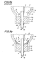
- Fig. 9(a) is a sectional view for illustrating a preferred end structure of such a ceramic discharge tube.
- a main body 11 of the ceramic discharge tube has a tubular shape with throttled opposite end portions.
- the main body 11 is provided with cylindrical end portions 12 at respectively opposite ends.
- the main body 11 and the end portions 12 are made of, for example, a sintered alumina body.
- the inn surface 11a of the main body 11 is of a curved shape. Since the inner surface 12a of the end portion 12 is straight as viewed in an axial direction of the main body, a corner 15 is formed between the main body 11 and the end portion 12.
- a sealing member 30 is inserted and held inside the end portion 12.
- a through-hole 30a is formed in the sealing member 30, extending in an axial direction.
- a slender current conductor 5 is fixedly inserted inside the through-hole 30a.
- the current conductor 5 is of a cylindrical shape, and is to introduce an ionizable light-emitting material into an interior space 13 of the main body 11 through an interior space 5a of the current conductor 5.
- To an outer terminal end of the current-passing conductor 5 is sealingly provided a sealed portion 5b after the starting gas and the ionizable material are sealed. The gases are sealed inside the discharge tube by the sealed portions 5b.
- An electrode shaft 7 is joined to the current conductor 5.
- the sealing member 30 has a cylindrical hollow contour shape with a flat face 30b. It is necessary to effect sealing between the sealing member 30 and the ceramic discharge tube and between the sealing member 30 and the current conductor 5.
- the current conductor is inserted into the through hole of the sealing member, an assembly is produced by inserting the sealing member into each of the end portions of the main body, and the assembly is integrally sintered.
- a firing shrinkage rate of the sealing member 30 is made smaller than that of the material constituting the ceramic discharge tube, so that the sealing member is intimately and sealingly fitted to the end portions of the discharge tube, whereas the sealing member is sealed to the current conductor through the firing shrinkage of the material of the sealing member 30.
- a glass layer 14 is usually formed around a portion of the current conductor 5 projecting outside the sealing member 30.
- the present inventors have discovered that there were the following problems in the above discharge lamp. That is, the metal halide, etc. are sealed inside the interior space 13 of the main body 11.
- the discharge lamp is repeatedly turned on and off. Most of the metal halide is distributed inside the interior space 13 of the main body 11 in the form of a gas phase during lightening, whereas a remaining part of the metal halide maintains its liquid phase state.
- the liquid phase halide may partially flow, in a direction of an Arrow A, toward the relatively lower end portion 12.
- the metal halide used in this lamp under consideration of a light-emitting efficiency exhibits corrosion against the ceramic discharge tube, and particularly against the alumina sintered body, when in the liquid phase.
- a portion surrounding the corner portion 15 is corroded, and as shown in Fig. 9(b), a corroded face 33 may be formed.
- the corroded face 33 is retracted in a direction of an Arrow B. Since the liquid phase metal halide 32 is likely to be stored along the corroded face 33, corrosion is more likely to occur along this corroded face 33. If such corrosion proceeds, it causes the fracture of the discharge lamp. In view of this, it is necessary to prevent occurrence of the corrosion.
- the present inventors made investigations to suppress the corrosion of the corner portion 15 by positioning the inner surface 34a of the sealing member 34 at a location contacting the corner portion 15 as shown in Fig. 10.
- the end portion of the inner surface 11a of the main body 11 and the inner surface 34a of the sealing member 34 tended to be corroded, for example, as shown by a dotted line 36.
- a portion near the corner portion 15 of the main body 11 was also corroded so that it might cause reduction of the life of the discharge lamp.
- EP-A-80820 discloses a discharge lamp having a silica tube filled with mercury metal halide. It also discloses a lamp with a ceramic tube, having a sodium filling. In both cases a reservoir is provided in an end of the tube adjacent the electrode shank, and a transfer means, such as a wick, is provided to move the liquid filling towards the electrode.
- EP-A-528428 shows a discharge lamp similar to that of Fig. 9 of the present specification, having a ceramic tube having an edge at a junction of the main tube body and an end portion of the tube body containing a sealing member.
- the discharge lamp according to the present invention is set out in claim 1.
- the present inventors have made investigations on the corrosion problem in the areas between the main body and the end portions of the ceramic discharge tube as mentioned above, but they found it difficult to reduce the corrosion. For this reason, the inventors have made investigations again on the mechanism through which this corrosion proceeded, and discovered that the liquid phase of the remaining metal halide stayed at the end portion, particularly at a portion surrounding the corner portion, which promoted the corrosion there. In view of this, the present inventors have come to consider that the storing recess is preliminarily formed on the surface of the sealing member itself on the side of the interior space so as to store the liquid phase of the ionizable light-emitting material, and the liquid phase of the metal halide is stored in this storing recess of the sealing member.
- the storing recess it is preferable to have an inclination on the surface of the storing recess. More specifically, it is preferable to form the storing recess such that the thickness of the recessed sealing member as viewed in the central axis direction of the ceramic discharge tube (the thickness of the sealing member as viewed in a direction in which the through-hole extends) decreases laterally from the corner portion to the through-hole of the sealing member. By so doing, the depth of the storing recess increases from the peripheral edge of the ceramic discharge tube to the center thereof.
- the gas phase of the ionizable light-emitting material flowing from the interior space of the main body is likely to be liquefied and stay at a portion near a central axis of the ceramic discharge tube, that is, a low temperature portion of the light-emitting tube. Therefore, a peripheral portion of the ceramic discharge tube is less likely to be corroded.
- the inner surface of the main body of the ceramic discharge tube smoothly continues to the storing recess with no step. That is, it is preferable that the corner portion between the main body and the end portion of the ceramic discharge tube is not seen as a step at the inner surface of the ceramic discharge tube.
- the edge of the sealing member is preferably aligned to be contact with the corner of the main body so that the corner may not be seen as a step from the outside.
- the inner surface of the storing recess of the sealing member is smoothly connected to the inner peripheral surface of the main body.
- the present invention is applied to the discharge lamp in which any of various kinds of ionizable light-emitting metal halide material is sealed.
- the present invention is more preferably applied to a metal halide lamp in which a metal halide having a highly corrosive property is sealingly filled.
- the invention is further preferably applied to the discharge lamp in which the ceramic discharge tube is made of alumina ceramic.
- the light-emitting efficiency of the discharge lamp is enhanced by decreasing the weight of the sealing member when the power (watt) of the lamp is small.
- the volume i.e., the thickness of the sealing member.
- the liquid metal halide staying in the storing recess comes to invade the sealing member from the storing recess in the thickness direction thereof, it is necessary to give an excess thickness to the sealing member.
- the dimension of the sealing member is to be reduced particularly in case that the power (watt) is small, it is preferable that the surface of the sealing member on the side of the interior space of the main body is covered with a covering film having resistance against metal halide.
- the liquid metal halide is led to the storing recess formed at the sealing member and invasion of the metal halide into the sealing member can be retarded. Therefore, the necessary thickness from the surface of the storing recess to the outer end surface of the sealing member can be reduced.
- the current conductor current conductors made of various kinds of high melting point metals or high melting point conductive ceramics may be used. However, from the standpoint of the conductivity, the high melting point metal is preferred. As such a high melting point metal, one or more kinds of metals selected from the group consisting of molybdenum, tungsten, rhenium, niobium, tantalum and their alloys.
- the coefficients of thermal expansion of niobium and tantalum substantially match that of the ceramic, particularly the alumina ceramic, constituting the ceramic discharge tube.
- these metals are likely to be corroded with the metal halide. Therefore, in order to ensure a long use life of the current conductor, it is preferable that the current conductor is made of molybdenum, tungsten, rhenium or an alloy thereof.
- molybdenum, tungsten, and rhenium generally exhibit smaller coefficients of thermal expansion.
- the coefficient of thermal expansion of the alumina ceramic is 8 x 10 -6 K -1
- that of molybdenum 6 x 10 -6 K -1 and that of tungsten and rhenium is less than 6 x 10 -6 K -1 .
- the current conductor can be gas-tightly kept at the sealing member, as mentioned later, by inserting the current conductor through the through-hole of the molded or calcined sealing member and then integrally firing the resulting assembly as it is.
- the current conductor is of a tubular shape.
- the thickness of the tubular current conductor is not more than 0.25 mm. Since the current conductor is a member which firmly holds the electrode shaft and the electrode, it is preferable to set the thickness of the tubular current corrector at not less than 0.1 mm.
- the same kind as that of the ceramic discharge tube may be used or a material different from that of the ceramic discharge tube may be used.
- the sealing member may be formed from the same material as that of the ceramic discharge tube.
- the current conductor is made of niobium or tantalum
- it is preferable that the sealing member is made of the same kind of a ceramic material as that of the ceramic discharge tube. By so doing, the coefficients of thermal expansion of the current conductor, the ceramic discharge tube and the sealing member can be approximated to one another.
- the "same kind" of the materials means that a ceramic is common as a base material, although additional component or components may be different.
- the ceramic discharge tube and the sealing member are made of the same kind of the material, for example, alumina ceramic
- a gap may be formed between the sealing member and the current conductor due to the difference in thermal expansion as the discharge lamp is used for a long time.
- the discharge lamp exhibits excellent color rendering and the maximum cool point is 700°C, relatively large strain occurs in the ceramic material. Consequently, when the turning on/off cycle is repeated at about 500 times, a gap may be formed between the current conductor and the sealing member.
- the sealing member is composed of a composite material constituted by a first component having a higher coefficient of thermal expansion and a second one having a lower coefficient of thermal expansion.
- the first component of the composite material is preferably the same ceramic as that of the ceramic discharge tube.
- selection is made from the group consisting of high melting point metals having corrosion resistance against the metal halide, such as tungsten, molybdenum, rhenium, etc. and ceramics having lower coefficients of thermal expansion, such as aluminum nitride, silicon nitride, titanium carbide, silicon carbide, zirconium carbide, titanium diboride, zirconium diboride, etc.
- high corrosion resistance against the metal halide can be afforded upon the metal halide.
- the rate of the first component such as the alumina ceramic is 60 wt% to 90 wt%, whereas that of the second component is 40 wt% to 10 wt%.
- the reason why the alumina ceramic is preferred as the first component is that alumina has high corrosion resistance. Further, if the alumina component is incorporated into the composite material, a seam between the end portion of the ceramic discharge tube and the sealing member disappears through the solid diffusion reaction during the firing ordinarily at about 1,800°C or more, so that the joined portion has a substantially integrated structure.
- the above end structure of the ceramic discharge tube can be formed, for example, by the following method.
- a green ceramic discharge tube is formed by a blowing process in which a cylindrical molding having a swelled central portion is extruded from a ceramic material such as powdery alumina, while air is being fed into a molding, and drying and dewaxing the molding.
- a raw material for the sealing member is measured, and water, alcohol, organic binder, etc. are added to the raw material.
- the mixture is granulated by using a spray dryer or the like, thereby obtaining a molding granular powder.
- a green molded sealing member with a through-hole is produced by press molding the resulting powder.
- a current conductor is inserted through the through- hole of the molded sealing member, and the resulting assembly is calcined to scatter the molding aid, etc. Thereby, a calcined body is obtained.
- a calcined body is produced by scattering the molding aid, etc. from the molded body through calcining, and then the current conductor is inserted through the through-hole of the calcined body.
- tungsten oxide, molybdenum oxide or the like mixed as a second component for the sealing member is reduced when the molded body is heated at 1300 to 1600°C in a reducing atmosphere.
- the calcined body for the sealing member is inserted inside the end portion of the calcined body for the ceramic discharge tube, and the calcined bodies for the ceramic discharge tube and the sealing member are integrally fired.
- the ceramic discharge tube and the sealing member are integrally joined to each other, and the current conductor is firmly held through the firing shrinkage of the through-hole of the sealing member.
- the diameter of the through-hole after the firing in the state that the current conductor is not inserted through the through-hole of the calcined body for the sealing member is smaller than that of the current conductor before the insertion by 1 to 10 %.
- the inner diameter of the end portion of the fired ceramic discharge tube in state that the current conductor is not inserted through the through-hole of the calcined body for the sealing member is smaller than the outer diameter of the fired sealing member by 1 to 10 %.
- the above final firing is preferably carried out in the reducing atmosphere, and preferably at the temperature of 1700 to 1900°C.
- the reducing atmosphere is employed in the calcining and firing steps, reduction of the second component, such as tungsten, for the sealing member can be prompted, while oxidation thereof is prevented.
- the shape of the pressing mold is modified so that an inclined surface or a curved surface may be formed inside the pressing mold. Further, such an inclined or curved surface can be formed by mechanically working the surface of the molded body or the calcined body for the sealing member.
- the sealing member is composed of an inner portion inserted into the end portion of the ceramic discharge tube and an outer portion integrated with this inner portion and positioned outside the end portion of the discharge tube.
- the inner portion is made of the same material as that of the ceramic discharge tube
- the outer portion is made of a composition material having a coefficient of thermal expansion between that of the material for the ceramic discharge tube and that of the material for the current conductor.
- the current conductor is gas-tightly fixed to the outer portion of the sealing member. That is, the current conductor is not gas-tightly fixed to the inner portion of the sealing member.
- the shape of the ceramic discharge tube may be generally tubular, cylindrical, barrel-like or the like, whereas the current conductor is tubular. After an ionizable light-emitting material is sealingly filled in the interior of the discharge tube, the current conductor is sealed by laser welding or electron beam welding.
- Fig. 1 is a schematic view for illustrating a metal halide discharge lamp.
- a ceramic discharge tube 10 is arranged inside an outer tube 2 made of quartz glass or hard glass such that the central axis of the outer tube 2 is aligned with that of the ceramic discharge tube 10.
- the opposite ends of the outer cylinder 2 are gas-tightly closed with respective caps 3.
- the ceramic discharge tube 10 includes a barrel-shaped main body 11 with a swelled central portion and end portions 12 at the opposite ends of the main body 11, respectively.
- the ceramic discharge tube 10 is held by the outer cylinder 2 via two lead wires 1.
- Each lead wire 1 is connected to the cap 3 via a foil 4.
- the upper lead wire 1 is welded to a tubular or rodshaped current conductor 6, whereas the lower lead wire 1 is welded to a tubular current conductor 5.
- each current conductor 5, 6 is passed through a through-hole of each sealing member 8, and fixed thereto.
- an electrode shaft 7 inside the main body 11 by welding To each current conductor 5, 6 is gas-tightly connected an electrode shaft 7 inside the main body 11 by welding.
- a coil 9 is wound around the electrode shaft 7.
- the electrode unit is not limited particularly to the above construction, and for example, an end portion of the electrode shaft 7 is shaped in a spherical form so that this spherical portion may be used as an electrode.
- an inert gas such as argon and a metal halide are sealingly filled in an inner space 13 of the ceramic discharge tube 10, and mercury is also sealingly filled, if necessary.
- Fig. 2 is an enlarged sectional view for illustrating a vicinity of the end portion of the ceramic discharge tube shown in Fig. 1.
- the inner surface 11a of the main body 11 is curved, and the inner surface 12a of the end portion 12 is straight as viewed in the axial direction of the main body.
- a corner 15 is formed between the main body 11 and the end portion 12.
- the sealing member 8 is inserted and held inside the end portion 12.
- a through-hole 8a is formed in the sealing member 8 in the axial direction.
- a slender, tubular current conductor 5 is inserted through the through-hole 8a.
- a sealing portion 5b is fitted to the inner surface 5a at the outer end of the current conductor 5.
- a glass layer 14 is provided at a portion where the current conductor 5 projects form the sealing member 8.
- the current conductor 5 is passed through the through-hole 8a of a molded body or a calcined body for the sealing member 8, and an assembly is produced by inserting the resulting molded body or the calcined body into the end portion of a mold body or a calcined body for the ceramic discharge tube.
- This assembly is integrally fired.
- the sealing member 8 is made of a composite material or a cermet in which the same material as that of the ceramic discharge tube 10, preferably alumina is combined with the above-mentioned second component. By so doing, the coefficient of thermal expansion of the sealing member 8 is adjusted to be between that of the material for the ceramic discharge tube and that of the material for the current conductor 5.
- the surface of the sealing member 8 on the side of the interior space 13 is designed as an inclined surface 16.
- An outer edge of the inclined surface 16 is contacted with the corner 15 of the discharge tube such that the inclined surface 16 smoothly continues to the inner surface 11a of the main body 11, and no step appears between the main body 11 and the inclined surface 16.
- the inclined surface 16 straightly extends from its edge contacting the corner 15 toward the through-hole 8a as viewed in section.
- a storing recess 17A having an almost conical shape is formed in the sealing member 8 itself on the side of the interior space 13.
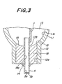
- Figs. 3, 4, 5 and 6 are enlarged sectional views for illustrating vicinities of end portions of ceramic discharge tubes of respective other embodiments of the present invention.
- the members already shown in Fig. 2 are denoted by the same reference numerals, and their explanation may be omitted.
- the surface of the sealing member 18 on the side of the interior space 13 is designed as a curved surface 19.
- the outer edge of this curved surface 19 contacts the corner 15 of the discharge tube such that the curved surface 19 smoothly continues to the inner surface 11a of the main body 11, and the corner 15 does not appear as a step between the main body and the curved surface 19.
- the curved surface 19 has almost the same inclined angle as that of the inner surface 11a of the main body 11 near the edge contacting the corner 15, and the inclination angle of the curved surface 19 gradually approaches to the horizon as the location comes near the through hole 18a. Consequently, the curved surface becomes horizontal near the through-hole 18a.
- a storing recess 17B is formed in the storing recess 17B on the side of the interior space 13. A liquid phase of the ionizable light-emitting material flowing to the end of the inner surface 11a of the main body 11 instantly goes into the storing recess 17B.
- a sealing member 20 has a cylindrical shape, and an outer peripheral covering portion 21 is provided at an end portion of the cylindrical sealing member 20 on the side of the interior space 13.
- This covering portion 21 has a shape almost fitting the inner surface 11a of the main body, and is designed in the form of a flange extending in a peripheral direction from the edge portion of the cylindrical portion.
- the corner 15 of the discharge tube and its vicinity are covered with this covering portion 21.
- the surface of the covering portion 21 on the side of the interior space 13 is designed as a curved surface 22.
- the outer edge of the curved surface 22 smoothly continues to the inner surface 11a of the main body 11.
- the curved surface 22 has almost the same inclination angle as that of the inner surface 11a of the main body 11 near the edge portion thereof. As the location approaches the through-hole 20a, the inclination angle of the curved surface 22 gradually approaches the horizon. As a result, a storing recess 17C is formed in the sealing member 20 itself on the side of the interior space 13. A liquid phase of the ionizable light-emitting material flowing to the end of the inner surface 11a of the main body 11 instantly goes into the storing recess 17B, and does not contact the corner 15 and its vicinity at all.
- the inner surface 11a of the main body 11 near the corner of the discharge tube is designed as an almost horizontal surface 23 as illustrated. Therefore, the angle of the corner between the inner surface 11a of the main body 11A and the inner surface of the end portion 12A is almost right angle.
- the surface of the sealing member 24 on the side of the interior space 13 is designed as an outer horizontal surface 25 and an inner curved surface 26. The edge of the horizontal or flat surface 25 contacts the corner 15 of the discharge tube such that the horizontal surface 25 smoothly continues to the horizontal portion.23 of the inner surface 11a of the main body 11A, and the corner 15 does not form a step between the main body 11A and the horizontal surface 25.
- the curved surface 26 is provided around the through hole 24a of the sealing member 24, and continues to the outer peripheral horizontal surface 25.
- the curved surface 26 is relatively largely inclined near the horizontal surface 25, and as the location approaches the through hole 24a, its inclination angle is decreased to the horizon.
- a relatively deep storing recess 17D is formed in the sealing member 24 itself on the side of the interior space 13 and inside the annular horizontal surface 25 as viewed in cross section.
- the sealing member 40 is constituted by an axially inner portion 27 and an axially outer portion 28.
- the inner portion 27 and the outer portion have been already explained before.
- the surface of the inner portion 27 on the side of the interior space 13 is designed as a curved surface 19.
- the outer edge of the curved surface 19 contacts a corner 15 of the discharge tube such that the curved surface 19 smoothly continues to the inner surface 11a of the main body 11, and the corner 15 forms no step between the main body 11 and the curved surface 19.
- the curved surface 19 has substantially the same inclination angle as that of the inner surface 11a near its edge portion contacting the corner 15. As the location approaches the through-hole 27a in the inner portion 27, the inclination angle of the curved surface 19 is gradually decreased to the horizon so that the curved surface is almost horizontal near the through-hole 27a. As a result, a storing recess 17B is formed at the sealing member 40 itself on the side of the interior space 13. A liquid phase of the ionizable light-emitting material flowing to the end of the inner surface 11a of the main body 11 instantly goes into the storing recess 17B.
- the outer portion 28 is made of the above-mentioned composite material.
- the current conductor 5 is inserted through a through-hole 28a of the outer portion 28, and the gas-tight sealing is effected there between the current conductor 5 and the outer portion 28.
- a glass layer 14 is formed around a portion of the current conductor 5 projecting from the outer portion 28.
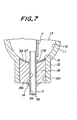
- Figs. 7 and 8 are enlarged sectional views for illustrating other embodiments of the ceramic discharge tube according to the present invention near end portions thereof, respectively, in which the surface of a sealing member on the side of the interior space is covered with a covering film having resistivity against the metal halide.
- the surface of the sealing member 18 on the side of the interior space 13 is designed as a curved surface 37.
- the curved surface 37 has substantially the same inclination angle as that of the inner surface 11 of the main body 11 near the edge portion on the side of the corner 15. As the location approaches the through-hole 18a from this edge, the inclination angle of the curved surface 37 is gradually decreased to the horizon so that the curved surface 37 is almost horizontal near the through-hole 18a.
- the covering film is formed over the entire curved surface 37.
- the outer edges of the curved surface 37 and the covering film 38 contact the edge portion 15 such that the covering film 38 smoothly continues to the inner surface 11a of the main body 11, and the corner 15 does not appear as a step between the main body 11 and the sealing member 18.
- a liquid phase of the ionizable light-emitting material flowing to the end of the inner surface 11a of the main body 11 instantly goes into the storing recess 17B.
- the surface of the sealing member 24 on the side of the interior space 13 is designed as a radially outer horizontal or flat surface 39 and a radially inner curved surface 40 located nearer the through-hole 24a than the horizontal surface 39. These surfaces 39 and 40 are smoothly continued at their opposed edges.
- the inclination angle of the curved surface 40 is gradually decreased to the horizon.
- a relatively deep storing recess 17D is formed at the sealing member 24 on the side of the interior space 13 and radially inside the annular horizontal surface 39 as viewed in a cross section.
- a covering film 38 having resistance against the metal halide is formed to cover the horizontal surface 39 and the curved surface 40.
- the radially outer edge of the covering film 38 contacts the corner 15 of the discharge tube such that the covering film 38 smoothly continues to the horizontal portion 23 of the inner surface 11a of the main body 11A, and the corner 15 does not appear as a step between the main body 11A and the sealing member 24.
- the covering film having resistance against the metal halide is preferably a metallized layer of a molybdenum-tungsten alloy or a covering film made of yttria ceramic.
- the discharge lamp comprises the ceramic discharge lamp having the interior space filled with the ionizable light-emitting metal halide material, the sealing member sealing the end portion of the ceramic discharge tube, and the current conductor inserted through the through-hole of the sealing member, wherein the corrosion of the ceramic discharge tube and particularly corrosion in the intermediate area between the main body and the end portion can be prevented to enhance use life of the ceramic discharge tube.
Landscapes
- Vessels And Coating Films For Discharge Lamps (AREA)
Claims (10)
- Entladungslampe, umfassendeine Keramik-Entladungsröhre (10) mit einem Innenraum (13), der mit einem ionisierbaren lichtaussendenden Metallhalogenidmaterial, das im kühlen Zustand eine Flüssigphase bildet, und einem Startergas gefüllt ist, wobei die Keramik-Entladungsröhre einen Hauptkörper (11) und zumindest einen Endabschnitt (12) umfasst, der mit einem Ende des Hauptkörpers verbunden ist; und mit einer Kante (15), die am Übergang zwischen der Innenfläche des Hauptkörpers und der Innenfläche des Endabschnitts (12) ausgebildet ist;ein Dichtungselement (8), das sich zumindest teilweise innerhalb des Endabschnitts befindet und daran befestigt ist, wobei durch das Dichtungselement hindurch ein Durchgangsloch (8a) ausgebildet ist; undeinen Stromleiter (5), der durch das Durchgangsloch des Dichtungselements hindurch eingesetzt und mit einer Elektrode (7, 9) verbunden ist, wobei kein Übertragungselement vorhanden ist, um die Flüssigphase zur Elektrode hin zu übertragen;gekennzeichnet durch eine Speicherausnehmung (17A, 17B usw.) zum Speichern der Flüssigphase aus dem ionisierbaren lichtaussendenden Material an der Innenfläche des Dichtungselements mit einer Basis, die von der Innenwand der Entladungsröhre beabstandet ist.
- Entladungslampe nach Anspruch 1, worin sich das Dichtungselement (8) im Endabschnitt (12) zur Kante (15) erstreckt und die Dicke des Dichtungselements (8) in axialer Richtung der Keramik-Entladungsröhre von der Kante (15) zum Durchgangsloch (8a) hin radial nach innen abnimmt.
- Entladungslampe nach Anspruch 1 oder 2, worin die Innenfläche des Hauptkörpers (11) der Entladungsröhre glatt ohne eine Stufe in die Oberfläche der Speicherausnehmung übergeht.
- Entladungslampe nach Anspruch 3, worin die radiale Außenkante der Innenfläche des Dichtungselements (8) die Kante (15) berührt.
- Entladungslampe nach Anspruch 1 oder 2, worin die Innenfläche des Dichtungselements (8) einen Überzugsfilm (38) aus einem Material aufweist, das Beständigkeit gegen das Metallhalogenid aufweist.
- Entladungslampe nach Anspruch 5, worin die radiale Außenkante des Überzugsfilms (38) glatt ohne eine Stufe in die Innenfläche des Hauptkörpers (11) übergeht.
- Entladungslampe nach Anspruch 1 oder 2, worin das Dichtungselement (18) an seiner Innenseite einen Deckabschnitt aufweist, der die Kante (15) bedeckt, und die Speicherausnehmung am Deckabschnitt auf der Seite des Innenraums ausgebildet ist.
- Entladungslampe nach Anspruch 7, worin die Innenfläche des Deckabschnitts mit einem Überzugsfilm aus einem Material bedeckt ist, das Beständigkeit gegen das Metallhalogenid aufweist.
- Entladungslampe nach einem der Ansprüche 1 bis 8, worin das Dichtungselement (8) aus einem Verbundmaterial mit einem Wärmedehnungskoeffizienten besteht, der zwischen jenem des Materials, das die Keramik-Entladungsröhre (11, 12) bildet, und jenem des Materials liegt, das den Stromleiter (5) bildet, und der Stromleiter gasdicht am Dichtungselement befestigt ist.
- Entladungslampe nach Anspruch 1, worin das Dichtungselement (8) einen axial inneren Abschnitt, der in den Endabschnitt der Keramik-Entladungsröhre eingesetzt ist, und einen axial äußeren Abschnitt umfasst, der mit dem axial inneren Abschnitt einstückig verbunden ist und außerhalb des Endabschnitts angeordnet ist, wobei der Innenabschnitt aus dem gleichen Material wie die Keramik-Entladungsröhre besteht, der Außenabschnitt aus einem Verbundmaterial besteht das einen Wärmeausdehnungskoeffizienten aufweist, der zwischen jenem des Materials, das die Keramik-Entladungsrohre (11,12) bildet, und jenem des Materials liegt, das den Stromleiter (5) bildet, und der Stromleiter gasdicht am Außenabschnitt des Dichtungselements befestigt ist.
Applications Claiming Priority (6)
| Application Number | Priority Date | Filing Date | Title |
|---|---|---|---|
| JP3914/95 | 1995-01-13 | ||
| JP391495 | 1995-01-13 | ||
| JP391495 | 1995-01-13 | ||
| JP06932395A JP3507179B2 (ja) | 1995-01-13 | 1995-03-28 | 高圧放電灯 |
| JP6932395 | 1995-03-28 | ||
| JP69323/95 | 1995-03-28 |
Publications (3)
| Publication Number | Publication Date |
|---|---|
| EP0722183A2 EP0722183A2 (de) | 1996-07-17 |
| EP0722183A3 EP0722183A3 (de) | 1996-10-30 |
| EP0722183B1 true EP0722183B1 (de) | 2001-11-07 |
Family
ID=26337582
Family Applications (1)
| Application Number | Title | Priority Date | Filing Date |
|---|---|---|---|
| EP96300248A Expired - Lifetime EP0722183B1 (de) | 1995-01-13 | 1996-01-12 | Entladungslampen |
Country Status (4)
| Country | Link |
|---|---|
| US (1) | US5783907A (de) |
| EP (1) | EP0722183B1 (de) |
| JP (1) | JP3507179B2 (de) |
| DE (1) | DE69616605T2 (de) |
Families Citing this family (27)
| Publication number | Priority date | Publication date | Assignee | Title |
|---|---|---|---|---|
| US6066918A (en) * | 1995-01-13 | 2000-05-23 | Ngk Insulators, Ltd. | High pressure discharge lamp with an improved sealing system and method of producing the same |
| WO1999031708A1 (en) * | 1997-12-16 | 1999-06-24 | Koninklijke Philips Electronics N.V. | High-pressure discharge lamp |
| TW503449B (en) * | 2000-04-18 | 2002-09-21 | Ngk Insulators Ltd | Halogen gas plasma-resistive members and method for producing the same, laminates, and corrosion-resistant members |
| JP2002141020A (ja) * | 2000-10-31 | 2002-05-17 | Ngk Insulators Ltd | 高圧放電灯用発光容器 |
| JP4206632B2 (ja) | 2000-10-31 | 2009-01-14 | 日本碍子株式会社 | 高圧放電灯用発光容器 |
| JP4144176B2 (ja) | 2000-11-22 | 2008-09-03 | 日本碍子株式会社 | 高圧放電灯用発光容器 |
| JP2002245971A (ja) | 2000-12-12 | 2002-08-30 | Toshiba Lighting & Technology Corp | 高圧放電ランプ、高圧放電ランプ点灯装置および照明装置 |
| US20020117965A1 (en) * | 2001-02-23 | 2002-08-29 | Osram Sylvania Inc. | High buffer gas pressure ceramic arc tube and method and apparatus for making same |
| JP3709560B2 (ja) * | 2002-01-21 | 2005-10-26 | 日本碍子株式会社 | 高圧放電灯用組み立て体および高圧放電灯 |
| JP2003346722A (ja) * | 2002-05-28 | 2003-12-05 | Nec Lighting Ltd | 高圧放電ランプおよびその製造方法 |
| US7839089B2 (en) * | 2002-12-18 | 2010-11-23 | General Electric Company | Hermetical lamp sealing techniques and lamp having uniquely sealed components |
| US7215081B2 (en) * | 2002-12-18 | 2007-05-08 | General Electric Company | HID lamp having material free dosing tube seal |
| US7132797B2 (en) * | 2002-12-18 | 2006-11-07 | General Electric Company | Hermetical end-to-end sealing techniques and lamp having uniquely sealed components |
| US20060001346A1 (en) * | 2004-06-30 | 2006-01-05 | Vartuli James S | System and method for design of projector lamp |
| US7358666B2 (en) | 2004-09-29 | 2008-04-15 | General Electric Company | System and method for sealing high intensity discharge lamps |
| WO2006046198A1 (en) * | 2004-10-26 | 2006-05-04 | Koninklijke Philips Electronics N.V. | A gas discharge lamp having a cold spot outside its translucent envelope |
| WO2006077516A2 (en) * | 2005-01-19 | 2006-07-27 | Koninklijke Philips Electronics N.V. | High-pressure discharge lamp |
| US7615929B2 (en) | 2005-06-30 | 2009-11-10 | General Electric Company | Ceramic lamps and methods of making same |
| US7852006B2 (en) | 2005-06-30 | 2010-12-14 | General Electric Company | Ceramic lamp having molybdenum-rhenium end cap and systems and methods therewith |
| US7432657B2 (en) * | 2005-06-30 | 2008-10-07 | General Electric Company | Ceramic lamp having shielded niobium end cap and systems and methods therewith |
| US7378799B2 (en) * | 2005-11-29 | 2008-05-27 | General Electric Company | High intensity discharge lamp having compliant seal |
| US20070138963A1 (en) * | 2005-12-19 | 2007-06-21 | General Electric Company | Ceramic arc chamber having shaped ends |
| DE102008060780A1 (de) * | 2008-12-05 | 2010-06-10 | Osram Gesellschaft mit beschränkter Haftung | Kurzbogenentladungslampe und Verfahren zu ihrer Herstellung |
| JP2012119129A (ja) * | 2010-11-30 | 2012-06-21 | Ngk Insulators Ltd | 発光管及びその製造方法 |
| CN103329238B (zh) * | 2011-02-22 | 2016-09-21 | 欧司朗有限公司 | 陶瓷放电容器和相关的灯具以及制造这种容器的方法 |
| EP2857534B1 (de) * | 2012-05-29 | 2020-10-28 | Kabushiki Kaisha Toshiba | Wolframlegierungsteil und entladungslampe, übertragungsröhre und magnetron damit |
| DE102014105300A1 (de) * | 2014-03-12 | 2015-09-17 | Von Ardenne Gmbh | Prozessieranordnung und Verfahren zum Betreiben einer Prozessieranordnung |
Family Cites Families (19)
| Publication number | Priority date | Publication date | Assignee | Title |
|---|---|---|---|---|
| EP0080820A3 (de) * | 1981-11-27 | 1983-12-14 | Thorn Emi Plc | Entladungslampe |
| US4665344A (en) * | 1984-04-25 | 1987-05-12 | Ngk Insulators, Ltd. | Ceramic envelope device for high-pressure discharge lamp |
| JPS6161338A (ja) * | 1984-08-31 | 1986-03-29 | Ngk Insulators Ltd | 高圧金属蒸気放電灯用発光管の製造方法 |
| US4742269A (en) * | 1984-11-09 | 1988-05-03 | Ngk Insulators, Ltd. | Ceramic envelope device for high-pressure discharge lamp |
| US4731561A (en) * | 1984-12-17 | 1988-03-15 | Ngk Insulators, Ltd. | Ceramic envelope device for high-pressure discharge lamp |
| US4868457A (en) * | 1985-01-14 | 1989-09-19 | General Electric Company | Ceramic lamp end closure and inlead structure |
| JPH0418204Y2 (de) * | 1986-10-03 | 1992-04-23 | ||
| JPH0682545B2 (ja) * | 1986-12-24 | 1994-10-19 | 日本碍子株式会社 | 高圧金属蒸気放電灯用発光管 |
| JPH073783B2 (ja) * | 1987-11-30 | 1995-01-18 | 東芝ライテック株式会社 | 高圧ナトリウムランプ |
| JPH0719575B2 (ja) * | 1988-03-16 | 1995-03-06 | 日本碍子株式会社 | 高圧金属蒸気放電灯用発光管及びその製造方法 |
| HU200031B (en) * | 1988-03-28 | 1990-03-28 | Tungsram Reszvenytarsasag | High-pressure discharge lamp |
| US5404078A (en) * | 1991-08-20 | 1995-04-04 | Patent-Treuhand-Gesellschaft Fur Elektrische Gluhlampen Mbh | High-pressure discharge lamp and method of manufacture |
| DE9112690U1 (de) * | 1991-10-11 | 1991-12-05 | Patent-Treuhand-Gesellschaft für elektrische Glühlampen mbH, 8000 München | Hochdruckentladungslampe |
| DE9206727U1 (de) * | 1992-05-18 | 1992-07-16 | Patent-Treuhand-Gesellschaft für elektrische Glühlampen mbH, 8000 München | Hochdruckentladungslampe |
| US5374872A (en) * | 1992-11-13 | 1994-12-20 | General Electric Company | Means for supporting and sealing the lead structure of a lamp and method for making such lamp |
| DE4242123A1 (de) * | 1992-12-14 | 1994-06-16 | Patent Treuhand Ges Fuer Elektrische Gluehlampen Mbh | Hochdruckentladungslampe mit einem keramischen Entladungsgefäß |
| EP0609477B1 (de) * | 1993-02-05 | 1999-05-06 | Patent-Treuhand-Gesellschaft für elektrische Glühlampen mbH | Keramisches Entladungsgefäss für Hochdruckentladungslampe und Herstellungsverfahren derselben und damit verbundene Dichtungsmaterialien |
| ATE155452T1 (de) * | 1993-12-10 | 1997-08-15 | Patent Treuhand Ges Fuer Elektrische Gluehlampen Mbh | Hochdruckentladungslampe mit keramischer entladungsröhre, dafür geeigneter keramischer körper und verfahren zu seiner herstellung |
| US5661367A (en) * | 1996-08-08 | 1997-08-26 | Philips Electronics North America Corporation | High pressure series arc discharge lamp construction with simplified starting aid |
-
1995
- 1995-03-28 JP JP06932395A patent/JP3507179B2/ja not_active Expired - Fee Related
-
1996
- 1996-01-11 US US08/583,838 patent/US5783907A/en not_active Expired - Fee Related
- 1996-01-12 EP EP96300248A patent/EP0722183B1/de not_active Expired - Lifetime
- 1996-01-12 DE DE69616605T patent/DE69616605T2/de not_active Expired - Fee Related
Also Published As
| Publication number | Publication date |
|---|---|
| DE69616605D1 (de) | 2001-12-13 |
| EP0722183A2 (de) | 1996-07-17 |
| JPH08250068A (ja) | 1996-09-27 |
| EP0722183A3 (de) | 1996-10-30 |
| DE69616605T2 (de) | 2002-08-01 |
| JP3507179B2 (ja) | 2004-03-15 |
| US5783907A (en) | 1998-07-21 |
Similar Documents
| Publication | Publication Date | Title |
|---|---|---|
| EP0722183B1 (de) | Entladungslampen | |
| US5352952A (en) | High-pressure discharge lamp with ceramic discharge vessel | |
| US5637960A (en) | Ceramic discharge vessel for a high-pressure discharge lamp, having a filling bore sealed with a plug, and method of its manufacture | |
| US5424608A (en) | High-pressure discharge lamp with ceramic discharge vessel | |
| JP3155651B2 (ja) | 高圧放電ランプ | |
| US6181065B1 (en) | Metal halide or sodium high pressure lamp with cermet of alumina, molybdenum and tungsten | |
| EP0926703B1 (de) | Metalldampfentladungslampe | |
| JP2000077030A (ja) | 高圧放電灯 | |
| EP1568066B1 (de) | Hockdruckgasentladungslampe und verfahren zur herstellung | |
| US7615929B2 (en) | Ceramic lamps and methods of making same | |
| JPH1173921A (ja) | セラミック放電管を備えたメタルハライドランプ | |
| CA2241656A1 (en) | Metal-halide discharge lamp having a ceramic discharge vessel with plugs through which electrical lead-throughs pass | |
| US4160930A (en) | Electric discharge lamp with annular current conductor | |
| EP2122663B1 (de) | Hochdruckentladungslampe mit keramischem entladungsgefäss | |
| JP2003532259A (ja) | 高圧放電ランプ | |
| US6404130B1 (en) | Metal halide lamp with fill-efficient two-part lead-through | |
| US6169366B1 (en) | High pressure discharge lamp | |
| US6590342B1 (en) | Metal halide lamp having halide resistant current conductors | |
| US6617790B2 (en) | Metal halide lamp with ceramic discharge vessel | |
| US20050200281A1 (en) | Seal for a discharge lamp | |
| US6262533B1 (en) | Starting electrode for high pressure discharge lamp | |
| JP4510670B2 (ja) | 高圧放電ランプ | |
| JP4273380B2 (ja) | 金属蒸気放電灯 | |
| EP1056116B1 (de) | Elektrode für eine Metallhalogenidlampe | |
| EP0926700B1 (de) | Elektrode für Hochdruckentladungslampe |
Legal Events
| Date | Code | Title | Description |
|---|---|---|---|
| PUAI | Public reference made under article 153(3) epc to a published international application that has entered the european phase |
Free format text: ORIGINAL CODE: 0009012 |
|
| AK | Designated contracting states |
Kind code of ref document: A2 Designated state(s): BE DE FR GB NL |
|
| PUAL | Search report despatched |
Free format text: ORIGINAL CODE: 0009013 |
|
| AK | Designated contracting states |
Kind code of ref document: A3 Designated state(s): BE DE FR GB NL |
|
| 17P | Request for examination filed |
Effective date: 19961106 |
|
| 17Q | First examination report despatched |
Effective date: 19971031 |
|
| GRAG | Despatch of communication of intention to grant |
Free format text: ORIGINAL CODE: EPIDOS AGRA |
|
| RTI1 | Title (correction) |
Free format text: DISCHARGE LAMPS |
|
| GRAG | Despatch of communication of intention to grant |
Free format text: ORIGINAL CODE: EPIDOS AGRA |
|
| GRAH | Despatch of communication of intention to grant a patent |
Free format text: ORIGINAL CODE: EPIDOS IGRA |
|
| GRAH | Despatch of communication of intention to grant a patent |
Free format text: ORIGINAL CODE: EPIDOS IGRA |
|
| GRAA | (expected) grant |
Free format text: ORIGINAL CODE: 0009210 |
|
| AK | Designated contracting states |
Kind code of ref document: B1 Designated state(s): BE DE FR GB NL |
|
| REF | Corresponds to: |
Ref document number: 69616605 Country of ref document: DE Date of ref document: 20011213 |
|
| REG | Reference to a national code |
Ref country code: GB Ref legal event code: IF02 |
|
| PLBE | No opposition filed within time limit |
Free format text: ORIGINAL CODE: 0009261 |
|
| STAA | Information on the status of an ep patent application or granted ep patent |
Free format text: STATUS: NO OPPOSITION FILED WITHIN TIME LIMIT |
|
| 26N | No opposition filed | ||
| PGFP | Annual fee paid to national office [announced via postgrant information from national office to epo] |
Ref country code: GB Payment date: 20061213 Year of fee payment: 12 |
|
| PGFP | Annual fee paid to national office [announced via postgrant information from national office to epo] |
Ref country code: DE Payment date: 20070131 Year of fee payment: 12 |
|
| PGFP | Annual fee paid to national office [announced via postgrant information from national office to epo] |
Ref country code: FR Payment date: 20070103 Year of fee payment: 12 |
|
| GBPC | Gb: european patent ceased through non-payment of renewal fee |
Effective date: 20080112 |
|
| PG25 | Lapsed in a contracting state [announced via postgrant information from national office to epo] |
Ref country code: DE Free format text: LAPSE BECAUSE OF NON-PAYMENT OF DUE FEES Effective date: 20080801 |
|
| REG | Reference to a national code |
Ref country code: FR Ref legal event code: ST Effective date: 20081029 |
|
| PG25 | Lapsed in a contracting state [announced via postgrant information from national office to epo] |
Ref country code: GB Free format text: LAPSE BECAUSE OF NON-PAYMENT OF DUE FEES Effective date: 20080112 |
|
| PG25 | Lapsed in a contracting state [announced via postgrant information from national office to epo] |
Ref country code: FR Free format text: LAPSE BECAUSE OF NON-PAYMENT OF DUE FEES Effective date: 20080131 |
|
| PGFP | Annual fee paid to national office [announced via postgrant information from national office to epo] |
Ref country code: BE Payment date: 20100201 Year of fee payment: 15 |
|
| PGFP | Annual fee paid to national office [announced via postgrant information from national office to epo] |
Ref country code: NL Payment date: 20100118 Year of fee payment: 15 |
|
| BERE | Be: lapsed |
Owner name: *NGK INSULATORS LTD Effective date: 20110131 |
|
| REG | Reference to a national code |
Ref country code: NL Ref legal event code: V1 Effective date: 20110801 |
|
| PG25 | Lapsed in a contracting state [announced via postgrant information from national office to epo] |
Ref country code: BE Free format text: LAPSE BECAUSE OF NON-PAYMENT OF DUE FEES Effective date: 20110131 |
|
| PG25 | Lapsed in a contracting state [announced via postgrant information from national office to epo] |
Ref country code: NL Free format text: LAPSE BECAUSE OF NON-PAYMENT OF DUE FEES Effective date: 20110801 |