EP0722025A1 - Protecting strip for a roof ridge - Google Patents
Protecting strip for a roof ridge Download PDFInfo
- Publication number
- EP0722025A1 EP0722025A1 EP94810730A EP94810730A EP0722025A1 EP 0722025 A1 EP0722025 A1 EP 0722025A1 EP 94810730 A EP94810730 A EP 94810730A EP 94810730 A EP94810730 A EP 94810730A EP 0722025 A1 EP0722025 A1 EP 0722025A1
- Authority
- EP
- European Patent Office
- Prior art keywords
- protective strip
- strip
- strip according
- tiles
- ridge
- Prior art date
- Legal status (The legal status is an assumption and is not a legal conclusion. Google has not performed a legal analysis and makes no representation as to the accuracy of the status listed.)
- Withdrawn
Links
- XLYOFNOQVPJJNP-UHFFFAOYSA-N water Substances O XLYOFNOQVPJJNP-UHFFFAOYSA-N 0.000 claims abstract description 17
- 229920002994 synthetic fiber Polymers 0.000 claims abstract description 5
- 230000035515 penetration Effects 0.000 claims abstract description 4
- 230000001681 protective effect Effects 0.000 claims description 56
- 238000009423 ventilation Methods 0.000 claims description 19
- 238000000034 method Methods 0.000 claims description 17
- 239000002390 adhesive tape Substances 0.000 claims description 13
- 239000000463 material Substances 0.000 claims description 13
- 239000004753 textile Substances 0.000 claims description 2
- 230000001070 adhesive effect Effects 0.000 abstract description 4
- 239000000853 adhesive Substances 0.000 abstract description 2
- 238000005273 aeration Methods 0.000 abstract description 2
- 239000011324 bead Substances 0.000 abstract 1
- 238000009434 installation Methods 0.000 description 8
- -1 polyethylene Polymers 0.000 description 5
- 239000004743 Polypropylene Substances 0.000 description 3
- 238000001125 extrusion Methods 0.000 description 3
- 229920001155 polypropylene Polymers 0.000 description 3
- 239000004698 Polyethylene Substances 0.000 description 2
- 238000010276 construction Methods 0.000 description 2
- 239000003292 glue Substances 0.000 description 2
- 230000001788 irregular Effects 0.000 description 2
- 238000004519 manufacturing process Methods 0.000 description 2
- 229920000573 polyethylene Polymers 0.000 description 2
- 229920000544 Gore-Tex Polymers 0.000 description 1
- 238000005520 cutting process Methods 0.000 description 1
- 238000009826 distribution Methods 0.000 description 1
- 230000002209 hydrophobic effect Effects 0.000 description 1
- 230000008595 infiltration Effects 0.000 description 1
- 238000001764 infiltration Methods 0.000 description 1
- 239000002184 metal Substances 0.000 description 1
- 229920000098 polyolefin Polymers 0.000 description 1
- 239000000565 sealant Substances 0.000 description 1
- 239000002023 wood Substances 0.000 description 1
Images
Classifications
-
- E—FIXED CONSTRUCTIONS
- E04—BUILDING
- E04D—ROOF COVERINGS; SKY-LIGHTS; GUTTERS; ROOF-WORKING TOOLS
- E04D1/00—Roof covering by making use of tiles, slates, shingles, or other small roofing elements
- E04D1/36—Devices for sealing the spaces or joints between roof-covering elements
-
- E—FIXED CONSTRUCTIONS
- E04—BUILDING
- E04D—ROOF COVERINGS; SKY-LIGHTS; GUTTERS; ROOF-WORKING TOOLS
- E04D13/00—Special arrangements or devices in connection with roof coverings; Protection against birds; Roof drainage ; Sky-lights
- E04D13/17—Ventilation of roof coverings not otherwise provided for
- E04D13/174—Ventilation of roof coverings not otherwise provided for on the ridge of the roof
- E04D13/176—Ventilation of roof coverings not otherwise provided for on the ridge of the roof formed by flexible material suitable to be rolled up
Definitions
- the present invention relates to a protective strip for the roof ridge, two possibilities of use and two methods of fitting such a strip.
- a first object of the invention is therefore to propose a protective strip, which can be placed under the ridge tiles, and capable of retaining water infiltration coming from the sides of the roof.
- a second object of the invention is to allow the protective strip also to allow ventilation of the roofing.
- Another object of the invention is to provide a protection strip that is easy to produce, that can be cut into rolls of determined length so that it can easily be used.
- yet another object of the invention is to propose installation methods adapted according to certain particularities.
- the invention firstly proposes a protective strip having the characteristics mentioned in claims 1 to 10, two particular modes of use being described in claims 11 and 12, while two methods of installation are specified in claims 13 and 14.
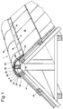
- FIG. 1 we see a section and a perspective of an upper portion of a roof 1 consisting of a row of ridge tiles 10, having a general shape of a portion of cylindrical tube, and whose edges 11 and 12 each rest on a surface portion close to the upper end of the tiles 13, 14 forming the upper row of tiles of each of the sections of the roof 1.
- the tiles 13, 14, as well as those forming the other rows of the roof, can be of any known type and are laid in a known manner on the tile slats 15, themselves arranged on a conventional frame may be of wood or metal.
- This frame comprises an ridge beam 16 arranged in the concave part of the ridge tiles 10.
- the protective strip 2 aims firstly to prevent this penetration of moisture and secondly to allow ventilation of the roofing.
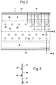
- the protective strip 2 consists of a strip made of a waterproof synthetic material , having a width between 30 and 50 cm for common roofs, this width can be adapted as required.
- the strip 2 comprises a central portion 20, bounded by two lateral portions 21.
- Each of the lateral portions 21 comprises on its edge close to the edge of the strip 2, an adhesive tape 22 disposed on the underside of the strip 2 and consisting of advantageously of a double-sided adhesive tape, glued to each edge of the strip 2, the other side of said tape remaining for the moment protected by a protective tape in a known manner.
- Ventper holes 24 can be regularly drilled on the two lateral sides of the central portion 20. These ventilation holes 20 will serve for the ventilation of the under -Roof as we will see later. These ventilation holes 24 can be arranged in a single row, as can be seen on the upper part of FIG. 2 or else in more than one row, being aligned or offset as seen on the lower part of the figure.
- a ventilation hole 25 of different execution shaped by a partial cutting of its periphery, so as to leave a tab forming a valve.
- this tab is oriented to the left, that is to the upper face of the protective strip 2, causing the ventilation hole 25 to open only when the ambient pressure is higher on the lower part of the protective strip, respectively in the sub-roof, than that prevailing on the upper part of the protective strip, respectively above the roof.
- Such an arrangement allows one-way ventilation from the inside of the roof to the outside.
- the protective strip 2 is obtained by extrusion of two sheets of synthetic material, preferably polyethylene or polypropylene, extruded in tandem and between which a mesh 26, made of textile threads or between, can be placed. synthetic, used to give a certain rigidity to the protective strip 2 and to prevent it from tearing. As a variant, it is also possible to extrude or laminate a sheet of polyethylene or polypropylene onto a strip of nonwoven material, the latter material ensuring the rigidity and the tear resistance of the assembly. As soon as this assembly has been carried out, according to one or other of the variants described, the adhesive tapes 22 and 23 can be applied and the ventilation holes, according to one or other of the embodiments shown in 24 or at 25, can be made by stamping. The protective strip 2 is then wound into a coil, which can be cut into standard lengths, for example 10 or 20 m, or then cut to measure according to the dimensions of the roof.
- synthetic used to give a certain rigidity to the protective strip 2 and to prevent it from tearing.
- the protective strip 2 is arranged and its operation.
- the protective strip 2 On a roof 1 in the process of finishing, that is to say on which the tiles 13, 14 of the side panels are laid, in particular the tiles of the upper rows, while the ridge tiles 10 are not yet laid, the protective strip 2, from one end of the ridge to the other, taking care that the central longitudinal axis 27 of the strip corresponds fairly well with the central line of the upper face of the ridge beam 16.
- the protective strip 2 is placed in the correct direction, that is to say that the adhesive tapes 22 are on the side of the tiles 13, 14, while the gutters 23 are on the face top of the strip 2 when it is laid.
- the lateral border of the protective strip 2 respectively the adhesive tape 22 is located just below or slightly set back from the edge 12 of the ridge tiles 10, while in the right portion of the figure, the lateral edge of the protective strip 2 exceeds by a few cm the edge 11 of the ridge tiles.
- the protective strip 2, in particular its lateral portions 21 will be wider than for the application of the first installation method. Roof ridge protection performed using the first installation method is more discreet and better protected from sunlight, while protection performed using the second installation method is more effective. Care should be taken to choose for this last installation method, materials having a color harmonized with that of the tiles for the portions of the protective strip exceeding the ridge tiles.
- the protective strip 2 both to allow ventilation of the roofing and to prevent the ingress of moisture.
- humidity under the roofing it can escape through the ventilation holes 24, 25 arranged on the central portion 20 of the strip 2, and pass directly under the ridge tiles 10 from where it may come out towards the outside through the gaps remaining between the edges 11 or 12 and the tiles 14 or the upper surface of the portion 21 of the strip 2.
- the droplets cannot infiltrate under the side edges 21 since these are directly glued to the tiles and do not leave any gaps.
- a drop of water which could be introduced through a gap between the border 12 and the tiles 14 in the case of laying according to the first method or between the border 11 and the upper face of the portion 21 in the case of laying according to the second method will be automatically stopped by one of the gutters 23 and will descend in the direction of the edge 11 or 12, without being able to access the central portion 20 and the ventilation holes 24 or 25.
- the adhesive tapes 22 and the gutters 23 may have some special characteristics. Since the adhesive tapes 22 are intended to be glued to tiles, generally in terracotta, it is necessary that their adhesive properties are optimum on this kind of material, this for a long time and that these adhesive properties remain constant despite sunshine and bad weather. In addition, given the relatively irregular shape of the upper surfaces of certain types of tiles, it is preferable to choose a relatively thick and malleable tape. A tape made of an adhesive sealant is particularly suitable.
- the shape of the cross section of the gutters 23 may for example be rectangular, or triangular or of any suitable shape.
- a ribbon of the same type as that described for the ribbons 22 can be used, given its hydrophobic qualities.
- the gutters can also be obtained, according to the desired shape, during this extrusion operation.
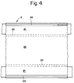
- the protective strip 2 no longer consists of an impermeable strip which is punctured in order to allow ventilation, as for the first form of execution described above, but rather a breathable strip on which there are two waterproof side strips to prevent the passage of water.
- the strip 2 can be made of a non-woven product, for example polypropylene, capable of allowing moist air to pass.
- the two waterproof lateral zones 21 it then suffices to deposit, glue or co-extrude two strips of waterproof material, for example two polyolefin films, the central portion 20 remaining consisting of the nonwoven product.
- the impermeable bands disposed on each side of the central portion 20 are applied to the upper face of the protective band 2, so as to prevent progression of the water by capillarity from the portions 21 towards the central portion 20.
- double-sided adhesive tapes 22 are arranged on the underside and on the two edges of the tape 2, while gutters 23 are arranged on the upper face of said tape, at the junction of the lateral portions 21 with the central portion 20.
- FIG. 4 can also represent a third embodiment of the protective strip 2 which then consists of a material having the capacities to let moist air pass and to block the passage of water more generally a semi material -permeable.
- a material having the capacities to let moist air pass and to block the passage of water more generally a semi material -permeable are generally known under the registered trademark GORE-TEX.
- GORE-TEX GORE-TEX
- the production of a strip according to one or the other of the two other embodiments can easily be carried out continuously in order to form rolls of suitable length.
- Protective strips 2 produced according to one or the other of the last two embodiments described can be applied according to one or other of the installation methods described with regard to the first embodiment of a bandaged. It should be noted that for these last two embodiments, there is always a combination of the two aeration and water retention operations.
- the protective strip has been described to be used on a hipped roof ending in a summit ridge, the skilled person will know adapt the dimensions and the distribution of the different portions of the strip according to the geometry of any type of roof.
Landscapes
- Engineering & Computer Science (AREA)
- Architecture (AREA)
- Civil Engineering (AREA)
- Structural Engineering (AREA)
- Roof Covering Using Slabs Or Stiff Sheets (AREA)
Abstract
Description
La présente invention concerne une bande de protection pour le faîte d'un toit, deux possibilités d'utilisation ainsi que deux méthodes de pose d'une telle bande.The present invention relates to a protective strip for the roof ridge, two possibilities of use and two methods of fitting such a strip.
Dans la construction traditionnelle d'un toit à deux pans, on a généralement deux rangées supérieures de tuiles, une sur chaque pan, partiellement recouvertes sur leurs extrémités supérieures, par une rangée de tuiles faîtières en forme de portion de tube cylindrique. Vu la forme généralement irrégulière des tuiles, des interstices subsistent sur la ligne de contact entre une bordure latérale de la rangée de tuiles faîtières et les tuiles sur lesquelles ces tuiles faîtières s'appuient. Ces interstices peuvent s'avérer utiles pour l'établissement d'un circuit d'aération de la sous-toiture, respectivement pour l'élimination de la vapeur d'eau qui y serait logée. Par contre, en cas de forte pluie, notamment lorsque la pluie est accompagnée d'un fort vent, les gouttes d'eau peuvent venir frapper le toit et particulièrement la rangée supérieure de tuiles selon une direction pouvant approcher de l'horizontale. Dans ce cas, l'eau peut pénétrer par capillarité sous les tuiles faîtières, va les interstices mentionnés et pénétrer ainsi dans la sous-toiture.In the traditional construction of a hipped roof, there are generally two upper rows of tiles, one on each side, partially covered at their upper ends, by a row of ridge tiles in the form of a portion of cylindrical tube. Given the generally irregular shape of the tiles, gaps remain on the contact line between a lateral border of the row of ridge tiles and the tiles on which these ridge tiles are based. These interstices can be useful for establishing a ventilation circuit for the roofing, respectively for eliminating the water vapor which would be housed there. On the other hand, in the event of heavy rain, in particular when the rain is accompanied by a strong wind, the drops of water can come to strike the roof and in particular the upper row of tiles in a direction which can approach the horizontal. In this case, the water can penetrate by capillarity under the ridge tiles, go to the interstices mentioned and thus penetrate into the roofing.
Un premier but de l'invention est donc de proposer une bande de protection, pouvant être disposée sous les tuiles faîtières, et capable de retenir les infiltrations d'eau en provenance des pans du toit.A first object of the invention is therefore to propose a protective strip, which can be placed under the ridge tiles, and capable of retaining water infiltration coming from the sides of the roof.
Un deuxième but de l'invention est de permettre que la bande de protection permette aussi l'aération de la sous-toiture.A second object of the invention is to allow the protective strip also to allow ventilation of the roofing.
Un autre but de l'invention est de proposer une bande de protection facile à réaliser, pouvant être débitée en rouleaux de longueur déterminée afin de pouvoir facilement être mise ën oeuvre.Another object of the invention is to provide a protection strip that is easy to produce, that can be cut into rolls of determined length so that it can easily be used.
Et enfin encore un autre but de l'invention est de proposer des modes de pose adaptés selon certaines particularités.And finally yet another object of the invention is to propose installation methods adapted according to certain particularities.
Afin d'atteindre ces buts, l'invention propose tout d'abord une bande de protection possédant les caractéristiques mentionnées dans les revendications 1 à 10, deux modes particuliers d'utilisation étant décrits dans les revendications 11 et 12, alors que deux méthodes de pose sont précisées dans les revendications 13 et 14.In order to achieve these aims, the invention firstly proposes a protective strip having the characteristics mentioned in claims 1 to 10, two particular modes of use being described in
L'invention est expliquée ci-dessous en regard du dessin annexé comportant les figures où:
- la figure 1 représente une vue en coupe et en perspective d'une portion supérieure d'un toit muni d'une bande de protection posée selon deux méthodes différentes,
- la figure 2 représente une première forme d'exécution d'une bande de protection,
- la figure 3 représente une coupe partielle selon la ligne III-III de la figure précédente, et
- la figure 4 représente deux autres formes d'exécution d'une bande de protection.
- FIG. 1 represents a sectional and perspective view of an upper portion of a roof provided with a protective strip laid according to two different methods,
- FIG. 2 represents a first embodiment of a protective strip,
- FIG. 3 represents a partial section along line III-III of the previous figure, and
- Figure 4 shows two other embodiments of a protective strip.
A la figure 1 on voit une coupe et une perspective d'une portion supérieure d'une toiture 1 constituée d'une rangée de tuiles faîtières 10, ayant une forme générale d'une portion de tube cylindrique, et dont les bordures 11 et 12 s'appuient chacune sur une portion de surface proche de l'extrémité supérieure des tuiles 13, 14 formant la rangée supérieure de tuiles de chacun des pans du toit 1. Les tuiles 13, 14, de même que celles formant les autres rangées de la toiture, peuvent être de n'importe quel type connu et sont posées selon une manière connue sur les lattes à tuiles 15, elles-mêmes disposées sur une charpente conventionnelle pouvant être en bois ou métallique. Cette charpente comprend une poutre faîtière 16 disposée dans la partie concave des tuiles faîtières 10. De par le procédé de fabrication des tuiles 10, 13, 14, de par les matériaux en lesquels elles sont constituées et de par leurs formes, il existe généralement une fente ou des interstices entre les bordures 11 ou 12 et respectivement les tuiles 13 ou 14. Si ces interstices permettent une aération de la sous-toiture par un flux passant de l'intérieur de la toiture vers l'extérieur, ils permettent malheureusement aussi un passage de l'humidité, notamment en cas de pluie, depuis l'extérieur de la toiture vers l'intérieur. La bande de protection 2 selon l'invention vise donc premièrement à empêcher cette pénétration d'humidité et secondairement à permettre l'aération de la sous-toiture.In Figure 1 we see a section and a perspective of an upper portion of a roof 1 consisting of a row of
Une première forme d'exécution d'une bande de protection 2 vue par dessous est visible sur la figure 2. Selon cette forme d'exécution, la bande de protection 2 est constituée d'une bande en un matériau synthétique imperméable à l'eau, ayant une largeur comprise entre 30 et 50 cm pour des toitures courantes, cette largeur pouvant être adaptée selon les besoins. La bande 2 comprend une portion centrale 20, limitée par deux portions latérales 21. Chacune des portions latérales 21 comprend sur sa bordure proche de la bordure de la bande 2, un ruban adhésif 22 disposé sur la face inférieure de la bande 2 et constitué de manière avantageuse d'un ruban autocollant à double face, collé sur chaque bordure de la bande 2, l'autre face dudit ruban restant pour le moment protégée par un ruban de protection selon une manière connue. Sur l'autre face de la bande de protection 2, à la limite entre les portions latérales 21 et la portion centrale 20, on peut trouver deux nervures en saillie 23, elles aussi constituées chacune avantageusement d'un ruban autocollant et destinées à former des gouttières dont l'usage sera expliqué plus loin. Si dans tous les cas les portions latérales restent imperméables à l'eau, des trous d'aération 24 peuvent être régulièrement percés sur les deux côtés latéraux de la portion centrale 20. Ces trous d'aération 20 serviront à l'aération de la sous-toiture comme on le verra plus loin. Ces trous d'aération 24 peuvent être disposés selon une seule rangée, comme on le voit sur la partie supérieure de la figure 2 ou alors sur plus d'une seule rangée, étant alignés ou décalés comme on le voit sur la partie inférieure de la figure. Sur cette même partie de la figure, on voit sur la droite un trou d'aération 25 d'exécution différente, façonné par une découpe partielle de son pourtour, de manière à laisser une languette formant clapet. Comme on le voit sur la figure 3, cette languette est orientée vers la gauche, soit vers la face supérieure de la bande de protection 2, faisant que le trou d'aération 25 ne s'ouvre que lorsque la pression ambiante est supérieure sur la partie inférieure de la bande de protection, respectivement dans la sous-toiture, que celle régnant sur la partie supérieure de la bande de protection, respectivement au-dessus du toit. Une telle disposition permet une aération à sens unique de l'intérieur de la toiture vers l'extérieur.A first embodiment of a
Selon une première forme d'exécution, la bande de protection 2 est obtenue par extrusion de deux feuilles en matériau synthétique, de préférence du polyéthylène ou du polypropylène, extrudées en tandem et entre lesquelles on peut placer un grillage 26, constitué de fils textiles ou synthétiques, servant à donner une certaine rigidité à la bande de protection 2 et à empêcher son déchirement. En variante, il est aussi possible d'extruder ou de contrecoller une feuille de polyéthylène ou de polypropylène sur une bande en matériau non tissé, ce dernier matériau assurant la rigidité et la résistance au déchirement de l'ensemble. Dès cet assemblage réalisé, selon l'une ou l'autre des variantes décrites, les rubans autocollants 22 et 23 peuvent être appliqués et les trous d'aération, selon l'une ou l'autre des formes d'exécution représentées en 24 ou en 25, peuvent être effectués par étampage. La bande de protection 2 est ensuite enroulée en une bobine, pouvant être coupée en longueurs standard, par exemple 10 ou 20 m, ou alors coupée sur mesure selon les dimensions de la toiture.According to a first embodiment, the
En revenant à la figure 1, on peut voir comment la bande de protection 2 est disposée ainsi que son fonctionnement. Sur une toiture 1 en voie de finition, c'est-à-dire sur laquelle les tuiles 13, 14 des pans latéraux sont posées, notamment les tuiles des rangées supérieures, alors que les tuiles faîtières 10 ne sont pas encore posées, on déroule la bande de protection 2, depuis une extrémité du faîte à l'autre, en veillant à ce que l'axe longitudinal central 27 de la bande corresponde assez bien avec la ligne centrale de la face supérieure de la poutre faîtière 16. Lors de cette opération, il s'agit de veiller à disposer la bande de protection 2 dans le bon sens, c'est-à-dire que les rubans autocollants 22 sont du côté des tuiles 13, 14, alors que les gouttières 23 sont sur la face supérieure de la bande 2 lorsqu'elle est posée. Afin de l'empêcher de bouger, on peut clouer ou agrafer la bande de protection 2, le long de l'axe longitudinal 27, sur la face supérieure de la poutre faîtière 16. En veillant à ce que la bande de protection 2 ne soit pas tendue latéralement afin de pouvoir ultérieurement disposer les tuiles faîtières 10 sans que celles-ci ne prennent appui sur la bande de protection, on peut maintenant retirer les rubans de protection des rubans autocollants 22 et coller chacune des bordures de la bande de protection 2 sur les tuiles 13, 14. Il ne reste plus qu'à déposer les tuiles faîtières 10 par dessus la bande de protection 2. On remarque sur la figure 1 deux méthodes de pose différents de la bande de protection 2. Sur la portion de gauche de la figure, la bordure latérale de la bande de protection 2, respectivement le ruban adhésif 22 est situé juste sous ou légèrement en retrait de la bordure 12 des tuiles faîtières 10, alors que sur la portion de droite de la figure, la bordure latérale de la bande de protection 2 dépasse de quelques cm la bordure 11 des tuiles faîtières. Pour une pose selon cette dernière méthode, la bande de protection 2, notamment ses portions latérales 21 seront plus larges que pour l'application de la première méthode de pose. Une protection de faîte d'un toit exécutée selon la première méthode de pose est plus discrète et mieux protégée du rayonnement solaire, alors qu'une protection effectuée selon la deuxième méthode de pose est plus efficace. On veillera à choisir pour ce dernier mode de pose, des matériaux ayant une couleur harmonisée à celle des tuiles pour les portions de la bande de protection dépassant les tuiles faîtières.Returning to Figure 1, we can see how the
Il est maintenant possible de décrire le fonctionnement de la bande de protection 2 tant pour permettre l'aération de la sous-toiture que pour empêcher la pénétration d'humidité. En cas d'humidité sous la sous-toiture, celle-ci peut s'échapper par les trous d'aération 24, 25 disposés sur la portion centrale 20 de la bande 2, et passer directement sous les tuiles faîtières 10 d'où elle pourra ressortir vers l'extérieur par les interstices subsistant entre les bordures 11 ou 12 et les tuiles 14 ou la surface supérieure de la portion 21 de la bande 2. Par contre, en cas de pluie, notamment d'une pluie chassée latéralement par du vent, les gouttelettes ne peuvent s'infiltrer sous les bordures latérales 21 vu que celles-ci sont directement collées sur les tuiles et ne laissent aucun interstice. Une goutte d'eau qui pourrait s'introduire par un interstice entre la bordure 12 et les tuiles 14 dans la cas d'une pose selon la première méthode ou entre la bordure 11 et la face supérieure de la portion 21 dans le cas d'une pose selon la deuxième méthode, sera automatiquement arrêtée par l'une des gouttières 23 et redescendra en direction de la bordure 11 ou 12, sans pouvoir accéder à la portion centrale 20 et aux trous d'aération 24 ou 25.It is now possible to describe the operation of the
Dans certains cas de construction, il se peut que d'autres moyens d'aération de la sous-toiture soient prévus que ceux passant par les interstices des tuiles faîtières. Dans ce cas, on pourrait s'abstenir de la nécessité de prévoir une portion de la bande de protection 2 qui soit perméable à l'air; on peut donc avoir alors une bande imperméable sur toute sa surface, empêchant ainsi uniquement la pénétration d'eau de l'extérieur vers l'intérieur de la toiture. Dans ce cas, il serait aussi possible de supprimer les gouttières 23 qui n'ont alors plus aucune utilité.In some cases of construction, it is possible that other means of ventilating the sub-roof are provided than those passing through the interstices of the ridge tiles. In this case, one could refrain from the need to provide a portion of the
Vu les méthodes de pose envisagées ainsi que le fonctionnement de la bande de protection tel que décrit, il peut être avantageux que les rubans adhésifs 22 ainsi que les gouttières 23 possèdent quelques caractéristiques particulières. Vu que les rubans adhésifs 22 sont destinés à être collés sur des tuiles, généralement en terre cuite, il est nécessaire que leurs propriétés adhésives soient optimum sur ce genre de matériau, ceci pour une longue durée et que ces propriétés adhésives restent constantes en dépit de l'ensoleillement et des intempéries. De plus, vu la forme relativement irrégulière des surfaces supérieures de certains types de tuiles, on choisira de préférence un ruban relativement épais et malléable. Un ruban constitué d'un mastic adhésif est particulièrement bien adapté. En ce qui concerne les gouttières 23, celles-ci doivent être relativement épaisses de manière à bien faire obstacle à une remontée d'eau en travers des portions latérales 21; la forme de la section transversale des gouttières 23 peut être par exemple rectangulaire, ou triangulaire ou de n'importe quelle forme adaptée. Un ruban du même type que celui décrit pour les rubans 22 peut être employé, vu ses qualités hydrophobe. En variante, et particulièrement lorsque la feuille de matériau synthétique faisant office de face supérieure de la bande de protection est obtenue par extrusion, les gouttières peuvent aussi être obtenues, selon la forme désirée, lors de cette opération d'extrusion.In view of the proposed laying methods as well as the operation of the protective strip as described, it may be advantageous for the
Selon une deuxième forme d'exécution de la bande de protection 2 visible à la figure 4, celle-ci est constituée non plus d'une bande imperméable que l'on perfore afin de permettre l'aération, comme pour la première forme d'exécution décrite précédemment, mais plutôt d'une bande perméable à l'air sur laquelle on dispose deux bandes latérales imperméables afin d'empêcher le passage de l'eau. Par exemple, la bande 2 peut être réalisée dans un produit non tissé, par exemple en polypropylène, capable de laisser passer l'air humide. Pour confectionner les deux zones latérales imperméables 21, il suffit alors de déposer, de coller ou de co-extruder deux bandes en matériau imperméable, par exemple deux films polyoléfine, la portion centrale 20 restant constituée du produit non tissé. Les bandes imperméables disposées de chaque côté de la portion centrale 20 sont appliquées sur la face supérieure de la bande de protection 2, de manière à éviter une progression de l'eau par capillarité depuis les portions 21 vers la portion centrale 20. Comme précédemment, des rubans adhésifs à double face 22 sont disposés sur la face inférieure et sur les deux bordures du ruban 2, alors que des gouttières 23 sont aménagées sur la face supérieure dudit ruban, à la jonction des portions latérales 21 avec la portion centrale 20.According to a second embodiment of the
La figure 4 peut aussi représenter une troisième forme d'exécution de la bande de protection 2 qui est constituée alors d'un matériau ayant les capacités de laisser passer l'air humide et de bloquer le passage de l'eau plus généralement un matériau semi-perméable. De tels matériaux sont connus généralement sous la marque déposée GORE-TEX. Dans ce cas, il suffit de disposer d'une bande de ce matériau selon la largeur voulue, sur laquelle on dispose de la même manière que précédemment les rubans adhésifs à double face 22 ainsi que les rubans 23 formant gouttières.FIG. 4 can also represent a third embodiment of the
Comme pour la première forme d'exécution décrite d'une bande de protection 2, la réalisation d'une bande selon l'une ou l'autre des deux autres formes d'exécution peut facilement être réalisée en continu afin de former des rouleaux de longueur convenable. Des bandes de protection 2 réalisées selon l'une ou l'autre des deux dernières formes d'exécution décrites peuvent être posées selon l'un ou l'autre des modes de pose décrits en regard de la première forme d'exécution d'une bande. Il est à remarquer que pour ces deux dernières formes d'exécution, on a toujours un cumul des deux opérations d'aération et de retenue d'eau.As for the first described embodiment of a
La bande de protection a été décrite pour être utilisée sur un toit à deux pans se terminant par une arête sommitale, l'homme du métier saura adapter les dimensions ainsi que la répartition des différentes portions de la bande selon la géométrie de n'importe quel type de toiture.The protective strip has been described to be used on a hipped roof ending in a summit ridge, the skilled person will know adapt the dimensions and the distribution of the different portions of the strip according to the geometry of any type of roof.
Claims (14)
Priority Applications (1)
| Application Number | Priority Date | Filing Date | Title |
|---|---|---|---|
| EP94810730A EP0722025A1 (en) | 1994-12-14 | 1994-12-14 | Protecting strip for a roof ridge |
Applications Claiming Priority (1)
| Application Number | Priority Date | Filing Date | Title |
|---|---|---|---|
| EP94810730A EP0722025A1 (en) | 1994-12-14 | 1994-12-14 | Protecting strip for a roof ridge |
Publications (1)
| Publication Number | Publication Date |
|---|---|
| EP0722025A1 true EP0722025A1 (en) | 1996-07-17 |
Family
ID=8218354
Family Applications (1)
| Application Number | Title | Priority Date | Filing Date |
|---|---|---|---|
| EP94810730A Withdrawn EP0722025A1 (en) | 1994-12-14 | 1994-12-14 | Protecting strip for a roof ridge |
Country Status (1)
| Country | Link |
|---|---|
| EP (1) | EP0722025A1 (en) |
Cited By (4)
| Publication number | Priority date | Publication date | Assignee | Title |
|---|---|---|---|---|
| EP0791699A1 (en) * | 1996-02-23 | 1997-08-27 | Alfons Knoche | Rollable ventilating capping for ridge and roof hip covering as well as a method for producing the same |
| WO1998004794A1 (en) * | 1996-07-29 | 1998-02-05 | Bts Gmbh & Co. Kg | Roof rear ventilating device |
| EP0854253A1 (en) * | 1997-01-17 | 1998-07-22 | Alfons Knoche | Extruded universal ventilator with pleated side elements |
| DE10029192A1 (en) * | 2000-06-19 | 2002-01-03 | Peter Wirz | Strip material for covering roof ridges and/or hips, comprises middle strip with cuts serving for formation of air flaps which open when middle strip is bent about its longitudinal axis |
Citations (9)
| Publication number | Priority date | Publication date | Assignee | Title |
|---|---|---|---|---|
| GB2015925A (en) * | 1978-03-06 | 1979-09-19 | Platon As | Roof Lining |
| FR2469514A1 (en) * | 1979-11-13 | 1981-05-22 | Verdun Pierre | Ventilated roof ridge tile - has convex top and returned side sections which contain ventilation holes and are retained by hooks |
| FR2497255A1 (en) * | 1980-12-30 | 1982-07-02 | Manet Claude | Universal ridge closure for roof of building - has integral cutter and bib allowing ridge construction without mortar |
| FR2561690A1 (en) * | 1984-03-21 | 1985-09-27 | Chenel Guy | Flexible intermediate ceiling sheet with fire sprinkler provision |
| EP0341343A2 (en) * | 1988-05-10 | 1989-11-15 | BRAAS GmbH | Water-tight strip for ridge or roof edge coverings |
| DE3829408A1 (en) * | 1988-08-30 | 1990-03-01 | Norm Amc Ag | Device for ventilating roofs |
| DE3835131A1 (en) * | 1988-10-15 | 1990-04-19 | Johannes Heyen | Method of fixing roofing and ceiling webs of ECB |
| EP0556761A2 (en) * | 1992-02-14 | 1993-08-25 | Alfons Knoche | Ridge ventilating system for saddle roofs |
| DE9319360U1 (en) * | 1993-12-16 | 1994-02-17 | Fleck Oskar | Cover strips for a ridge or ridge |
-
1994
- 1994-12-14 EP EP94810730A patent/EP0722025A1/en not_active Withdrawn
Patent Citations (9)
| Publication number | Priority date | Publication date | Assignee | Title |
|---|---|---|---|---|
| GB2015925A (en) * | 1978-03-06 | 1979-09-19 | Platon As | Roof Lining |
| FR2469514A1 (en) * | 1979-11-13 | 1981-05-22 | Verdun Pierre | Ventilated roof ridge tile - has convex top and returned side sections which contain ventilation holes and are retained by hooks |
| FR2497255A1 (en) * | 1980-12-30 | 1982-07-02 | Manet Claude | Universal ridge closure for roof of building - has integral cutter and bib allowing ridge construction without mortar |
| FR2561690A1 (en) * | 1984-03-21 | 1985-09-27 | Chenel Guy | Flexible intermediate ceiling sheet with fire sprinkler provision |
| EP0341343A2 (en) * | 1988-05-10 | 1989-11-15 | BRAAS GmbH | Water-tight strip for ridge or roof edge coverings |
| DE3829408A1 (en) * | 1988-08-30 | 1990-03-01 | Norm Amc Ag | Device for ventilating roofs |
| DE3835131A1 (en) * | 1988-10-15 | 1990-04-19 | Johannes Heyen | Method of fixing roofing and ceiling webs of ECB |
| EP0556761A2 (en) * | 1992-02-14 | 1993-08-25 | Alfons Knoche | Ridge ventilating system for saddle roofs |
| DE9319360U1 (en) * | 1993-12-16 | 1994-02-17 | Fleck Oskar | Cover strips for a ridge or ridge |
Cited By (4)
| Publication number | Priority date | Publication date | Assignee | Title |
|---|---|---|---|---|
| EP0791699A1 (en) * | 1996-02-23 | 1997-08-27 | Alfons Knoche | Rollable ventilating capping for ridge and roof hip covering as well as a method for producing the same |
| WO1998004794A1 (en) * | 1996-07-29 | 1998-02-05 | Bts Gmbh & Co. Kg | Roof rear ventilating device |
| EP0854253A1 (en) * | 1997-01-17 | 1998-07-22 | Alfons Knoche | Extruded universal ventilator with pleated side elements |
| DE10029192A1 (en) * | 2000-06-19 | 2002-01-03 | Peter Wirz | Strip material for covering roof ridges and/or hips, comprises middle strip with cuts serving for formation of air flaps which open when middle strip is bent about its longitudinal axis |
Similar Documents
| Publication | Publication Date | Title |
|---|---|---|
| EP0894644B1 (en) | Pressure-activated adhesive sheet | |
| US5002816A (en) | Sealing strip for a ridging | |
| NL1031112C2 (en) | Tape and method for manufacturing thereof. | |
| EP3303723B1 (en) | Panel, assembly of panels, and associated roof | |
| FR2597531A1 (en) | PROCESS FOR ASSEMBLING BETWEEN PANNELS, SUCH AS S ROOFING PATCHES, OF A MATERIAL IN MINERAL FIBERS IN THE FORM OF ROLLS, MAT OF MINERAL FIBERS FOR THE IMPLEMENTATION OF THE SAME AND ITS OBTAINING PROCEDURE | |
| FR2538434A1 (en) | COVERING LUCARNE WITH SEALING DEVICE | |
| MXPA02010638A (en) | Fastening with wide fastening membrane. | |
| EP0354149B1 (en) | Process and device for the sealed connection of plates exposed to rain | |
| EP0399874B1 (en) | Batten assembly, particularly for covering of pitched roofs | |
| WO2004051020A1 (en) | Flexible thermal insulation material comprising at least one open-work layer | |
| EP0415825B1 (en) | Pitched roof isolation, particularly for old constructions | |
| EP0722025A1 (en) | Protecting strip for a roof ridge | |
| EP3712344B1 (en) | Ventilated ridge closure for roof | |
| FR2981103A3 (en) | STRIP OF DESOLIDARIZATION | |
| FR2874947A1 (en) | Composite sandwich panels assembling and connecting method for forming e.g. insulating veranda roof, involves forming two edge trim sections having symmetrical shapes, and assembling panels by embedding key joint in grooves via flange | |
| EP3943684B1 (en) | Flashing flap and sealing device for a roof, and method for assembling such a device | |
| EP1382767B1 (en) | Wind-resistant roof tile | |
| EP0068989A2 (en) | Heat insulating module for insertion between a building-roof element ands its covering | |
| FR2520787A1 (en) | Cleat for roof ventilation - has fixing between tile batten and sealed rafter screen with gap for air circulation | |
| JP2769450B2 (en) | Tiled structure | |
| EP3034712A1 (en) | Support for under-tile insulating plate | |
| BE1008735A6 (en) | Ridge of tile eaves. | |
| FR2680532A1 (en) | Bituminous barrier sheeting for the production of coverings | |
| EP1625265B1 (en) | Method and device for tight juxtaposition of panels and panels provided with said device | |
| FR2577592A1 (en) | COVER PANEL, IN PARTICULAR FOR ROOFING |
Legal Events
| Date | Code | Title | Description |
|---|---|---|---|
| PUAI | Public reference made under article 153(3) epc to a published international application that has entered the european phase |
Free format text: ORIGINAL CODE: 0009012 |
|
| AK | Designated contracting states |
Kind code of ref document: A1 Designated state(s): AT CH DE FR IE LI |
|
| STAA | Information on the status of an ep patent application or granted ep patent |
Free format text: STATUS: THE APPLICATION IS DEEMED TO BE WITHDRAWN |
|
| 18D | Application deemed to be withdrawn |
Effective date: 19970120 |