EP0721835B2 - Geformte Filamentstrukturen und Verfahren zu deren Herstellung - Google Patents
Geformte Filamentstrukturen und Verfahren zu deren Herstellung Download PDFInfo
- Publication number
- EP0721835B2 EP0721835B2 EP95120649A EP95120649A EP0721835B2 EP 0721835 B2 EP0721835 B2 EP 0721835B2 EP 95120649 A EP95120649 A EP 95120649A EP 95120649 A EP95120649 A EP 95120649A EP 0721835 B2 EP0721835 B2 EP 0721835B2
- Authority
- EP
- European Patent Office
- Prior art keywords
- sectors
- layers
- layer
- tape
- filaments
- Prior art date
- Legal status (The legal status is an assumption and is not a legal conclusion. Google has not performed a legal analysis and makes no representation as to the accuracy of the status listed.)
- Expired - Lifetime
Links
Images


Classifications
-
- B—PERFORMING OPERATIONS; TRANSPORTING
- B29—WORKING OF PLASTICS; WORKING OF SUBSTANCES IN A PLASTIC STATE IN GENERAL
- B29C—SHAPING OR JOINING OF PLASTICS; SHAPING OF MATERIAL IN A PLASTIC STATE, NOT OTHERWISE PROVIDED FOR; AFTER-TREATMENT OF THE SHAPED PRODUCTS, e.g. REPAIRING
- B29C70/00—Shaping composites, i.e. plastics material comprising reinforcements, fillers or preformed parts, e.g. inserts
- B29C70/04—Shaping composites, i.e. plastics material comprising reinforcements, fillers or preformed parts, e.g. inserts comprising reinforcements only, e.g. self-reinforcing plastics
- B29C70/28—Shaping operations therefor
- B29C70/54—Component parts, details or accessories; Auxiliary operations, e.g. feeding or storage of prepregs or SMC after impregnation or during ageing
- B29C70/543—Fixing the position or configuration of fibrous reinforcements before or during moulding
-
- B—PERFORMING OPERATIONS; TRANSPORTING
- B29—WORKING OF PLASTICS; WORKING OF SUBSTANCES IN A PLASTIC STATE IN GENERAL
- B29C—SHAPING OR JOINING OF PLASTICS; SHAPING OF MATERIAL IN A PLASTIC STATE, NOT OTHERWISE PROVIDED FOR; AFTER-TREATMENT OF THE SHAPED PRODUCTS, e.g. REPAIRING
- B29C70/00—Shaping composites, i.e. plastics material comprising reinforcements, fillers or preformed parts, e.g. inserts
- B29C70/04—Shaping composites, i.e. plastics material comprising reinforcements, fillers or preformed parts, e.g. inserts comprising reinforcements only, e.g. self-reinforcing plastics
- B29C70/06—Fibrous reinforcements only
- B29C70/10—Fibrous reinforcements only characterised by the structure of fibrous reinforcements, e.g. hollow fibres
- B29C70/16—Fibrous reinforcements only characterised by the structure of fibrous reinforcements, e.g. hollow fibres using fibres of substantial or continuous length
- B29C70/22—Fibrous reinforcements only characterised by the structure of fibrous reinforcements, e.g. hollow fibres using fibres of substantial or continuous length oriented in at least two directions forming a two-dimensional [2D] structure
- B29C70/228—Fibrous reinforcements only characterised by the structure of fibrous reinforcements, e.g. hollow fibres using fibres of substantial or continuous length oriented in at least two directions forming a two-dimensional [2D] structure the structure being stacked in parallel layers with fibres of adjacent layers crossing at substantial angles
-
- B—PERFORMING OPERATIONS; TRANSPORTING
- B29—WORKING OF PLASTICS; WORKING OF SUBSTANCES IN A PLASTIC STATE IN GENERAL
- B29D—PRODUCING PARTICULAR ARTICLES FROM PLASTICS OR FROM SUBSTANCES IN A PLASTIC STATE
- B29D99/00—Subject matter not provided for in other groups of this subclass
- B29D99/0082—Producing articles in the form of closed loops, e.g. rings
-
- B—PERFORMING OPERATIONS; TRANSPORTING
- B32—LAYERED PRODUCTS
- B32B—LAYERED PRODUCTS, i.e. PRODUCTS BUILT-UP OF STRATA OF FLAT OR NON-FLAT, e.g. CELLULAR OR HONEYCOMB, FORM
- B32B18/00—Layered products essentially comprising ceramics, e.g. refractory products
-
- C—CHEMISTRY; METALLURGY
- C04—CEMENTS; CONCRETE; ARTIFICIAL STONE; CERAMICS; REFRACTORIES
- C04B—LIME, MAGNESIA; SLAG; CEMENTS; COMPOSITIONS THEREOF, e.g. MORTARS, CONCRETE OR LIKE BUILDING MATERIALS; ARTIFICIAL STONE; CERAMICS; REFRACTORIES; TREATMENT OF NATURAL STONE
- C04B35/00—Shaped ceramic products characterised by their composition; Ceramics compositions; Processing powders of inorganic compounds preparatory to the manufacturing of ceramic products
- C04B35/71—Ceramic products containing macroscopic reinforcing agents
- C04B35/78—Ceramic products containing macroscopic reinforcing agents containing non-metallic materials
- C04B35/80—Fibres, filaments, whiskers, platelets, or the like
- C04B35/83—Carbon fibres in a carbon matrix
-
- F—MECHANICAL ENGINEERING; LIGHTING; HEATING; WEAPONS; BLASTING
- F16—ENGINEERING ELEMENTS AND UNITS; GENERAL MEASURES FOR PRODUCING AND MAINTAINING EFFECTIVE FUNCTIONING OF MACHINES OR INSTALLATIONS; THERMAL INSULATION IN GENERAL
- F16D—COUPLINGS FOR TRANSMITTING ROTATION; CLUTCHES; BRAKES
- F16D69/00—Friction linings; Attachment thereof; Selection of coacting friction substances or surfaces
- F16D69/02—Composition of linings ; Methods of manufacturing
- F16D69/023—Composite materials containing carbon and carbon fibres or fibres made of carbonizable material
-
- B—PERFORMING OPERATIONS; TRANSPORTING
- B29—WORKING OF PLASTICS; WORKING OF SUBSTANCES IN A PLASTIC STATE IN GENERAL
- B29K—INDEXING SCHEME ASSOCIATED WITH SUBCLASSES B29B, B29C OR B29D, RELATING TO MOULDING MATERIALS OR TO MATERIALS FOR MOULDS, REINFORCEMENTS, FILLERS OR PREFORMED PARTS, e.g. INSERTS
- B29K2105/00—Condition, form or state of moulded material or of the material to be shaped
- B29K2105/06—Condition, form or state of moulded material or of the material to be shaped containing reinforcements, fillers or inserts
- B29K2105/08—Condition, form or state of moulded material or of the material to be shaped containing reinforcements, fillers or inserts of continuous length, e.g. cords, rovings, mats, fabrics, strands or yarns
- B29K2105/0809—Fabrics
- B29K2105/0827—Braided fabrics
-
- B—PERFORMING OPERATIONS; TRANSPORTING
- B29—WORKING OF PLASTICS; WORKING OF SUBSTANCES IN A PLASTIC STATE IN GENERAL
- B29L—INDEXING SCHEME ASSOCIATED WITH SUBCLASS B29C, RELATING TO PARTICULAR ARTICLES
- B29L2031/00—Other particular articles
- B29L2031/709—Articles shaped in a closed loop, e.g. conveyor belts
-
- C—CHEMISTRY; METALLURGY
- C04—CEMENTS; CONCRETE; ARTIFICIAL STONE; CERAMICS; REFRACTORIES
- C04B—LIME, MAGNESIA; SLAG; CEMENTS; COMPOSITIONS THEREOF, e.g. MORTARS, CONCRETE OR LIKE BUILDING MATERIALS; ARTIFICIAL STONE; CERAMICS; REFRACTORIES; TREATMENT OF NATURAL STONE
- C04B2237/00—Aspects relating to ceramic laminates or to joining of ceramic articles with other articles by heating
- C04B2237/30—Composition of layers of ceramic laminates or of ceramic or metallic articles to be joined by heating, e.g. Si substrates
- C04B2237/32—Ceramic
- C04B2237/38—Fiber or whisker reinforced
- C04B2237/385—Carbon or carbon composite
-
- Y—GENERAL TAGGING OF NEW TECHNOLOGICAL DEVELOPMENTS; GENERAL TAGGING OF CROSS-SECTIONAL TECHNOLOGIES SPANNING OVER SEVERAL SECTIONS OF THE IPC; TECHNICAL SUBJECTS COVERED BY FORMER USPC CROSS-REFERENCE ART COLLECTIONS [XRACs] AND DIGESTS
- Y10—TECHNICAL SUBJECTS COVERED BY FORMER USPC
- Y10T—TECHNICAL SUBJECTS COVERED BY FORMER US CLASSIFICATION
- Y10T428/00—Stock material or miscellaneous articles
- Y10T428/21—Circular sheet or circular blank
- Y10T428/213—Frictional
-
- Y—GENERAL TAGGING OF NEW TECHNOLOGICAL DEVELOPMENTS; GENERAL TAGGING OF CROSS-SECTIONAL TECHNOLOGIES SPANNING OVER SEVERAL SECTIONS OF THE IPC; TECHNICAL SUBJECTS COVERED BY FORMER USPC CROSS-REFERENCE ART COLLECTIONS [XRACs] AND DIGESTS
- Y10—TECHNICAL SUBJECTS COVERED BY FORMER USPC
- Y10T—TECHNICAL SUBJECTS COVERED BY FORMER US CLASSIFICATION
- Y10T428/00—Stock material or miscellaneous articles
- Y10T428/24—Structurally defined web or sheet [e.g., overall dimension, etc.]
- Y10T428/24033—Structurally defined web or sheet [e.g., overall dimension, etc.] including stitching and discrete fastener[s], coating or bond
-
- Y—GENERAL TAGGING OF NEW TECHNOLOGICAL DEVELOPMENTS; GENERAL TAGGING OF CROSS-SECTIONAL TECHNOLOGIES SPANNING OVER SEVERAL SECTIONS OF THE IPC; TECHNICAL SUBJECTS COVERED BY FORMER USPC CROSS-REFERENCE ART COLLECTIONS [XRACs] AND DIGESTS
- Y10—TECHNICAL SUBJECTS COVERED BY FORMER USPC
- Y10T—TECHNICAL SUBJECTS COVERED BY FORMER US CLASSIFICATION
- Y10T428/00—Stock material or miscellaneous articles
- Y10T428/24—Structurally defined web or sheet [e.g., overall dimension, etc.]
- Y10T428/24058—Structurally defined web or sheet [e.g., overall dimension, etc.] including grain, strips, or filamentary elements in respective layers or components in angular relation
- Y10T428/24124—Fibers
Definitions
- This invention relates to fibrous substrates for the production of carbon and/or ceramic (including mixtures of these) fiber reinforced carbon and/or ceramic (including mixtures of these) composites and to methods of manufacture of same.
- exemplary of such a composite is a carbon fiber/carbon matrix brake disk made by depositing a carbon matrix on a carbon fiber substrate of the invention, the fibrous material of the substrate being carbonized to reinforce the carbon matrix with carbon fibers.
- Deposition of carbon on the substrate is effected by in situ cracking of a carbon bearing gas (hereinafter referred to as carbon vapor deposition, abbreviated “CVD” or carbon vapor infiltration, abbreviated “CVI”, as these terms are used interchangeably for purposes of the present invention) or by repeatedly impregnating the substrate with a carbon bearing resin and thereafter charring such resin or a combination of such methods to density the carbon matrix on the carbonized substrate.
- CVD carbon vapor deposition
- CVI carbon vapor infiltration
- the invention is not directed to formation of the carbon matrix or densification of the carbon fiber substrate, but rather to the substrate, its preparation, and subsequent densification in known manner to provide a carbon fiber reinforced composite, especially one suitable for use as a friction disk in a brake or clutch.
- a preferred material for use in the invention is polyacrylonitrile (PAN) fiber which, particularly if CVD is to be employed, is preferably in an oxidized condition which facilitates subsequent carbonization.
- PAN polyacrylonitrile
- Greige PAN fiber and carbon fiber or graphite fiber may also be found to be suitable.
- Oxidized PAN fiber (which may hereinafter be referred to as "OPF") is available commercially in various forms, including tows, yarns, woven and non-woven fabrics, knit fabrics and felts.
- OPF tow such as that available from RKT of Muir of Ord, Scotland.
- Tows and/or yarns of PAN fibers, carbon fibers, graphite fibers, ceramic fibers, precursors of carbon fibers and precursors of ceramic fibers, and mixtures of these may be used.
- the term “tow” is used to refer to a strand of continuous filaments.
- the term “yarn” is used to refer to a continuous strand of continuous or staple fibers or blends of these; thus the term “yam” encompasses tow.
- Continuous fiber is generally preferred over discontinuous fiber due to enhanced mechanical properties in the resultant composite product.
- annuli are cut out of parallel-sided multi-layered sheets of PAN fiber material to form one or more substrate annuli. This procedure results in considerable wastage of expensive PAN or OPF sheet and the offcut material cannot be reprocessed to continuous filament form to make anew continuous filament sheet.
- the amount of offcut waste generated in the production of preforms to be used in production of disks for aircraft braking systems is reduced by preparation of a shaped filamentary structure in the following manner: needlepunching a unidirectional layer of filaments to provide a degree of dimensional stability; cutting a plurality of segments from the unidirectional layer of needlepunched material; assembling a plurality of such segments in side-by-side contiguous relationship to produce a filamentary layer of the required structural shape; superposing at least one similar layer on the first layer; and needlepunching the superposed layers to assemble and join the segments.
- segmented strips of resin impregnated carbon or graphite cloth are assembled in partially overlapping relationship with opposite ends at opposite faces of the disk.
- the disk is formed and cured under high temperature and pressure to bond the segmented strips together.
- the cured disk is then pyrolyzed to produce a carbon or graphite char bond matrix.
- arcuate sectors of resin impregnated carbon or graphite cloth are assembled in stacked annular layers with the radial joints formed by the abutted ends of the sectors of each layer being offset circumferentially relative to those of adjacent layers.
- a method of making a multi-layered annular shaped fibrous structure (10, 40) having a radius and a thickness comprising the steps of: forming a multidirectional fabric (30, 50) having filaments (12) extending in at least two directions; cutting arcuate or trapezoidal sectors (20, 20') of an annular shape from said multidirectional fabric, each sector having a radial width (22, 22') generally corresponding to the radial width (24)of the fibrous structure to be formed; assembling the sectors (20, 20') in contiguous relationship to form an annular layer (26) having a radial width (22) generally corresponding to the radial width (24) of the fibrous structure to be formed; providing a stack (29) of thus formed layers of fibrous material, one layer on top of another; and needlepunching the stacked layers (26) to produce cross-linking of the layers by filaments (15) displaced out of the layers (26) and extending in a direction generally perpendicular to the faces (17, 18) of the
- a flat annular multi-layered fibrous structure (10,40,60,70,80) having a radius and a thickness comprising a stack (29) of layers (26) of fibrous material, one layer on top of another, that are cross-linked to one another by filaments (15) displaced out of the layers (26) so as to extend in a direction generally perpendicular of the faces (17,18) of the layers (26), the layers (26) being formed from arcuate or trapezoidal sectors (20,20') of an annular shape from a multidirectional fabric (30,50) having filaments (12) that extend in at least two directions, each sector having a radial width (22,22') generally corresponding to the radial width (24) of the fibrous structure; the sectors (20,20') being in contiguous or overlapping relationship to form an annular or helical layer (26,41,70,80) having a radial width (22,22',45) generally corresponding to the radial width (24) of the fibrous structure
- suitable friction disk preforms can be made from various fibrous tapes formed by joinder of arcuate or trapezoidal shaped sectors cut from a multidirectional fabric such as braided, knit, woven and non-woven fabrics, the sectors being needlepunched as they are stacked or coiled layer upon layer.
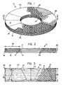
- Figure 1 is an isometric view of a friction disk according to an embodiment of the invention.
- Figure 2 is an enlarged sectional view taken along plane 2-2 of Figure 1, depicting schematically the fiber distribution therein.
- Figure 3 is a schematic depiction showing layout of arcuate sectors to be cut out of a strip or tape of a multidirectional fabric.
- Figure 4 is a plan schematic view of an embodiment of an annular shaped filamentary structure according to the invention formed from a helical tape formed of joined arcuate sectors of a multidirectional fabric.
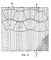
- Figure 5 is a plan view depicting a layout of arcuate sectors to be cut out from a large strip of of a a multidirectional fabric.
- Figure 6 is an exploded schematic view of an embodiment of an annular shaped filamentary structure according to the invention formed from a pair of helical tapes.
- a friction disk 10 comprising a stack 29 superposed annular layers 26 formed by joinder of substantially identical arcuate sectors 20 of multidirectional fabric derived from tows 12 of OPF cross-linked to one another by filaments 15 ( Figure 2) displaced from layers 26 by needlepunching to consolidate and densify a preform disk similar to preform disk 40 shown in Figure 4, the OPF having been converted to carbon fiber and further densified after needlepunching by carbon matrix deposition using conventional CVI processes.
- the cross-linked layers may have deposited thereon a matrix of carbon, ceramic, precursor of carbon, precursor of ceramic, and mixtures of these to further bind together the cross-linked layers.
- Each annular layer 26 in the embodiment shown in Figures 1 and 2 is formed of six substantially identical arcuate sectors 20 positioned side by side.
- the filaments of tows 12 within the disk 10 may be substantially continuous within each respective arcuate sector 20 between the inside diameter (ID) and outside diameter (OD) cylindrical peripheral surfaces 14, 16 of the disk 10 and its flat, parallel wear faces 17, 18 except those filaments 15 that have been displaced perpendicularly to the wear faces 17, 18 by needlepunching to join the sectors.
- Continuous fiber i.e. filament
- the sectors 20, 20' may be cut from a narrow strip such as strip 30 as shown in Figure 3 or a wide sheet such as sheet 50 as shown in Figure 5 and joined end to end or in overlapping manner to form a fibrous layer 26 of the required structural shape which may be joined to another fibrous layer by needlepunching of the stacked layers to form a fibrous preform such as an annular preform disk.
- the sectors 20, 20' may be joined end to end or in overlapping manner to form a helical fibrous tape ( Figures 4, 6, 7, 8) or an annular layer ( Figures 1, 2).
- the helical tape may be arranged to form a flat, hollow annular preform disk having a plurality of fibrous layers such as preform 40 as shown in Figure 4.
- Sectors 20,20' or a helical tape 41 formed from sectors 20, 20' may be interleaved with an additional helical fibrous tape, formed for example, by collapsing a helical hollow tubular braid as described in U.S.-A-5,217,770 to Morris and Liew.
- a helical flat braid tape 61 may be interleaved with helical turns 62 formed of sectors 20 joined end to end or in overlapping manner.
- the braided helical tape 61 itself may be formed from one or more of side by side parallel braids which may be partially overlapped.
- the fiber volume i.e., the quantity of fiber per unit volume, which is usually expressed as a percentage with zero percent meaning that no fiber is present and one hundred percent meaning that only fiber is present, is essentially the same throughout each sector and thus any preform or disk formed exclusively from such sectors.
- the fiber volume is greater adjacent the inner periphery 14 of disk 10 and adjacent the outer periphery 16 of disk 10, than in the remainder of the disk 10.
- This variation in fiber volume is a natural result of forming an otherwise uniform straight tubular braid into a flattened annulus or helix.
- This naturally occurring variation in fiber volume associated with a curved braid formed by bending a straight braid can be minimized by braiding techniques described in U.S.-A-5,217,770 to Morris and Liew.
- the sectors 20 having a radial width 22 are cut out from a straight braid 30 having a width 35.
- braid 30 is a multidirectional fabric, as contrasted with a unidirectional fabric as described in the aforementioned patents to Lawton et al.
- the ends of adjacent sectors 20 may be contiguous as they are laid out and cut from braid such as braid 30 shown in Figure 3 or tridirectional crosslapped fabric 50 shown in Figure 5. As shown, very little offcut waste is generated compared to known methods, including that shown and described in the above mentioned patents to Lawton et al. Adjacent sectors 20 may be laid out 180 degrees relative to one another.
- the braid 30 in the preferred embodiment shown in Figure 3 is obtained by collapsing or flattening a straight tubular braid.
- a system of longitudinal members 34 extending in the lengthwise direction of the braid is introduced into the braid as it is formed. These longitudinal members 34 may be referred to as "unidirectionals".
- unidirectionals 34 improve the dimensional stability as well as the tensile strength, compressive strength and moduli, and fiber volume of the tri-directional fabric.
- Unidirectionals 34 are introduced from stationary guide eyes in the braiding machine such that the unidirectionals will lie straight (without crimp) parallel to the braid axis 33 (longitudinal direction of the braid) while the helical braid members 31 introduced by the braiding machine carriers pass over and under the unidirectionals as the braided fabric 30 is formed.
- Straight braid 30 inherently has greater lateral stability than the unidirectional "fabric" of Lawton et al.
- Straight braid 30 may be needlepunched prior to cutting sectors 20 therefrom to provide even greater dimensional stability of the braid itself and the sectors to be cut therefrom.
- braid members and/or unidirectionals of different materials may benefit final mechanical or other properties, e.g. vibration damping, of the needlepunched and densified structure.
- Such materials could include other carbon-based and/or ceramic-based fibers.
- the braiding members and/or unidirectionals may be formed of staple fibers.
- the preform disk 40 comprises one or more helical turns 43 symmetrical about axis 44 of a fibrous tape 41 previously formed of arcuate sectors 20 joined end to end, e.g. by sewing with thread 42.
- the radial width of the tape 41 generally corresponds to the radial distance 24 between the inner periphery 14 and the outer periphery 16 of the flat annulus.
- the included angle of each sector 20 is such that the radial joints 45 of adjacent layers each formed of otherwise identical sectors are not aligned, e. g. sixty-seven degrees.
- the helical turns 43 of tape 41 are needlepunched to join them together.
- preform disk 40 is similar in appearance to that of friction disk 10 illustrated in Figure 1.
- One or more additional helically wound tapes may be interleaved with fibrous tape 41 to form a flat, hollow annular structure having a plurality of interleaved filamentary layers.
- the layers are joined by needlepunching which displaces filaments perpendicularly relative to the faces of the layers to cross-link the layers into an assembly.
- the longitudinal axis 46 of one of the groups of the filaments 12 in each sector 20 is disposed chordally relative to the arc of each respective sector and tangentially relative to the annular shaped structure 40.
- trapezoidal sector 20' which may be trimmed to the arcuate shape of sector 20 after manufacture of tape 41 or preform disk 40.
- a sheet or strip of multidirectional fabric such as crosslapped fabric 50 is shown.
- Fabric 50 is formed in known manner by needling together unidirectional webs of side by side filaments which webs are superposed such that the filaments of any unidirectional web forming the fabric cross at an angle to the filaments of any other unidirectional web forming the fabric.
- the fabric 50 consists of three layers of unidirectional webs and the angle of crossing of the filaments of any web is about sixty degrees relative to any other web forming the fabric 50. It is also possible to produce a suitable fabric using crossing layers, one of which is of parallelised staple fibers from a carding machine. Such carded layer may be formed from offcut waste fiber.
- a preform 60 having an axis of symmetry 66 is made from two helically wound tapes 61, 62 of dissimilar construction.
- Turns 61 of a tape of continuous helical braid may be interleaved with turns 62 of fibrous tape formed from sectors 20 to form a flat, hollow annular structure having a plurality of interleaved filamentary layers.
- the tape layers are joined by needlepunching which displaces filaments perpendicularly relative to the faces of the layers to cross-link the layers into an assembly.
- Fibrous tape 41 is made by sewing together with thread 42 the radial joints 45 of the abutting circumferentially spaced ends of the adjacent sectors 20 prior to needlepunching of the stacked layers.
- This enables handling of a plurality of end to end abutted arcuate sectors 20 as a single helical tape portion 41 which can be guided into a rotary needlepunch loom such as that described in DE-A-2911762 to Dilo or WO-A-93/15250 to Lawton and Smith.
- presewing of the abutted sectors prevents separation of the abutting ends during needlepunching.
- a suitable straight braid such as braid 30 of Figure 3 may be formed from a plurality of tows 12, e.g. 12k OPF tow, on a conventional tubular braiding machine (not illustrated).
- a simplified version of a conventional Maypole-type braiding machine and its operation are illustrated in U.S.-A- 3,007,497 to Shobert.
- An eminently suitable braiding machine having one hundred forty-four carriers and seventy-two unidirectional positions is available from W. STEEGER GmbH & Co. of Wuppertal, Germany.
- PPI picks/2.54cm
- picks/inch picks/inch
- the braid For a straight collapsed tubular braid formed of 12k tows of OPF and having a nominal width of 17.78cm (seven inches) when flattened, the braid has from about 2.5 to 5 picks/2.54cm (ppi).
- PPI is a complex function of braider speed, fibrous material pull out rate, angle of pull out and width of braid, and is empirically determined. Five PPI means that five crossovers of the members being braided occur per 2.54cm (one inch) of machine direction movement. PPI is conveniently determinable manually as the braid apparatus is empirically adjusted.
- an optional, additional curved braid such as curved braid 61 shown in Figure 6 may be interleaved with layers formed of sectors.
- a curved braid may be more accurately formed by a machine rather than manually as was previously done as described in US-A-5,217,770 to Morris et al. The machinery and manufacture of curved flattened tubular braid is described in USSN 08/149,854 filed November 10, 1993 entitled CURVED BRAID APPARATUS (now US-A- 5,417,138).
- One or more layers of fibrous sectors 20 are joined to one another and/or to one or more other fibrous layers superposed thereon by needlepunching.
- the arcuate sectors 20 are needlepunched into a unitary preform structure as they are fed continuously onto a rotating support. This may be accomplished using a rotary needlepunch loom-such as that described in DE-A-2911762 to Dilo.
- This Dilo machine is provided with a needling head whose effective width corresponds to the radial extent of the fibrous strip or the arcuate sectors and preform being assembled.
- the needling head of the apparatus shown in DE-A-2911762 to Dilo may be controlled programmed to avoid ovemeedling of the preform being made, which may occur at the inner periphery of the preform when using an apparatus such as that described in the aforementioned patents to Lawton et al.
- joinder of one or more layers of fibrous sectors 20 may be accomplished by arranging the fibrous sectors into one or more superposed layers in a needle penetrable mold or jig and passing the jig and layers to be assembled to and fro through a conventional needlepunch loom. This technique is more fully described in the aforementioned patents to Lawton et al. and in U.S.-A-5,217,770 to Morris and Liew.
- the resulting needlepunched structure may be thereafter subjected to CVD densification in conventional manner to produce a friction disk similar in appearance to disk 10 shown in Figure 1 having an average or bulk density of about 1.8 g/cm 3 .
- density is determined by weighing a specimen of known dimensions, such as that obtained by machining from the region of interest of a larger specimen, and is expressed as weight per unit volume, e.g., g/cm 3 .
- a plurality of such densified disks made according to the invention may be machined in conventional manner and assembled to form a multidisk brake similar to that shown and described in any of U.S.-A-4,018,482; 4,878,563; and 4,613,017.
- Recycled or virgin OPF staple may be used in the manufacture of yams to be formed into the fabric or fabrics to be used in manufacture of shaped filamentary structures of the invention.
- the tows be of PAN fiber in its oxidized state (OPF) when subjected to all textile processes described herein. While it may be possible to produce suitable preform disks out of greige PAN fiber and thereafter oxidize such preforms in a batch method as opposed to the continuous oxidation method employed in the manufacture of oxidized PAN fiber, this is not deemed most economical, particularly because prior to oxidation the PAN fiber does not have the desired high density nor is it able to withstand the high temperature of the furnace cycles desired to be employed subsequent to formation of the preform disk.
Landscapes
- Engineering & Computer Science (AREA)
- Chemical & Material Sciences (AREA)
- Composite Materials (AREA)
- Mechanical Engineering (AREA)
- Ceramic Engineering (AREA)
- Textile Engineering (AREA)
- Materials Engineering (AREA)
- General Engineering & Computer Science (AREA)
- Manufacturing & Machinery (AREA)
- Chemical Kinetics & Catalysis (AREA)
- Structural Engineering (AREA)
- Organic Chemistry (AREA)
- Nonwoven Fabrics (AREA)
- Braking Arrangements (AREA)
- Laminated Bodies (AREA)
- Manufacturing Of Multi-Layer Textile Fabrics (AREA)
- Braiding, Manufacturing Of Bobbin-Net Or Lace, And Manufacturing Of Nets By Knotting (AREA)
Claims (25)
- Verfahren zur Herstellung einer mehrschichtigen ringförmigen faserigen Struktur (10,40), die einen Radius und eine Dicke aufweist, mit den Schritten: Bildung eines multidirektionalen Textilproduktes (30,50), das Filamente (12) aufweist, die sich in mindestens zwei Richtungen erstrecken; Schneiden bogenförmiger oder trapezförmiger Sektoren (20, 20') einer Ringform aus dem multidirektionalen Textilprodukt, wobei jeder Sektor eine radiale Breite (22,22') hat, die im wesentlichen der radialen Breite (24) der zu bildenden faserigen Struktur entspricht; Aneinanderlegen der Sektoren (20,20') zur Bildung einer ringförmigen Schicht (26), die eine radiale Breite (22,22') hat, die im wesentlichen der radialen Breite (24) der zu bildenden faserigen Struktur entspricht; Bilden eines Stapels (29) aus derart gebildeten Schichten (26) faserigen Materials, wobei eine Schicht über der anderen angeordnet wird; und Vernadeln der gestapelten Schichten (26), um eine Vernetzung der Schichten (26) durch Filamente (15) zu erzeugen, die aus den Schichten (26) herausragen und sich in einer Richtung erstrecken, die im wesentlichen senkrecht zu den Stirnseiten (17,18) der Schichten (26) verläuft.
- Verfahren gemäß Anspruch 1, worin das multidirektionale Textilprodukt (30,50) Filamente (12) aufweist, die sich in drei Richtungen erstrecken, welche im wesentlichen parallel zu der durch das Textilprodukt definierten Ebene verlaufen.
- Verfahren gemäß Anspruch 2, worin die Längsachse (46) eines Filaments der Gruppen von Filamenten (12) in jedem Sektor in bezug auf die ringförmige Struktur (10,40) tangential angeordnet ist.
- Verfahren gemäß Anspruch 2, worin die Längsachse (46) eines Filaments der Gruppen von Filamenten in jedem Sektor (20) in bezug auf den Bogen des Sektors sehnenförmig angeordnet ist.
- Verfahren nach Anspruch 1, worin sämtliche Sektoren (20) im wesentlichen identisch sind.
- Verfahren nach Anspruch 1, worin die Enden der eine ringförmige Schicht (26) bildenden Sektoren (20) in bezug auf die Enden der Sektoren, welche eine unmittelbar benachbarte Schicht (26) bilden, in Umfangsrichtung gegeneinander versetzt sind.
- Verfahren nach Anspruch 1, ferner mit dem Bilden der Sektoren (20,20') durch Schneiden aus einem geflochtenen Textilprodukt (30).
- Verfahren nach Anspruch 7, ferner mit der Bildung eines flachgelegten, geraden, rohrförmigen Geflechts (30) mit unidirektionalen Strukturen (34), wobei das Geflecht eine Breite (35) hat, die im wesentlichen der radialen Breite (22,22') der zu bildenden Sektoren (20,20') entspricht.
- Verfahren gemäß Anspruch 1, ferner mit der Bildung eines schraubenlinienförmigen Bandes (41) durch Ende-an-Ende-Verbinden von Sektoren (20,20'), die aus einem der geflochtenen (30) und gekreuzt übereinanderliegenden vernadelten Textilprodukte (50) ausgeschnitten wurden, und Vernadeln von gestapelten Windungen (43) des Bandes.
- Verfahren gemäß Anspruch 9, worin die das Band (41) bildenden Sektoren (20,21) durch Nähen (42) Ende-an-Ende verbunden werden.
- Verfahren gemäß Anspruch 1, ferner mit der Bildung eines multidirektionalen Textilprodukts in Form eines schraubenlinienförmigen Bandes (70) durch Verbinden einer ersten Schicht (71) von aneinanderstoßenden Sektoren (20), die aus faserigem Material geschnitten sind, das aus der Gruppe gewählt ist, die eine vernadelte Schicht von unidirektionalen Filamenten, geflochtene Textilprodukte und gekreuzt übereinanderliegende vernadelte Textilprodukte enthält, mit einer zweiten Schicht (72) von aneinanderstoßenden Sektoren (20), die aus faserigem Material geschnitten sind, das aus der Gruppe gewählt ist, die eine vernadelte Schicht von unidirektionalen Filamenten, geflochtene Textilprodukte und gekreuzt übereinanderliegende vernadelte Textilprodukte enthält, durch Vernadelung der das Band (70) bildenden ersten und zweiten Schichten (71,72) und Vernadelung gestapelter Windungen des Bandes.
- Verfahren nach Anspruch 11, worin das Band (70) durch Vernadelung zweier koextensiver Schichten (71,72) gebildet wird, die jeweils aus Sektoren (20) gebildet werden, wobei die durch die angrenzenden Enden der ersten Schicht (71) gebildeten Verbindungen in bezug auf die Verbindungen versetzt angeordnet sind, die durch die angrenzenden Enden der Sektoren der zweiten Schicht (72) gebildet werden, welche das Band bilden.
- Verfahren gemäß Anspruch 1, worin ferner das multidirektionale Textilprodukt in Form eines schraubenlinienförmigen Bandes (80) gebildet wird, indem Sektoren (81), die aus faserigem Material geschnitten sind, das aus der Gruppe gewählt ist, die eine vernadelte Schicht von unidirektionalen Filamenten, geflochtene Textilprodukte und gekreuzt übereinanderliegende vernadelte Textilprodukte enthält, in einer partiell überlappenden Beziehung zu den gegenüberliegenden Enden jedes Sektors (81) an gegenüberliegenden Stirnseiten (82,83) des Bandes (80) angeordnet werden, die das Band (80) bildenden angeordneten Sektoren (81) vernadelt werden und gestapelte Windungen des Bandes (80) vernadelt werden.
- Verfahren gemäß Anspruch 1, worin ferner die Sektoren (20,20') durch Schneiden aus einem gekreuzt übereinanderverlaufenden vernadelten Textilprodukt (50) gebildet werden, das durch Vernadelung unidirektionaler Bahnen nebeneinander angeordneter Filamente gebildet wird, wobei die Bahnen derart übereinandergelegt werden, daß die Filamente jeder das Textilprodukt bildenden, unidirektionalen Bahn jede andere das Textilprodukt bildende, unidirektionale Bahn unter einem Winkel kreuzen.
- Verfahren nach Anspruch 14, worin der Kreuzungswinkel der Filamente jeder Bahn in bezug auf jede andere das gekreuzt übereinanderverlaufende vernadelte Textilprodukt bildenden Bahn ungefähr 60 Grad beträgt.
- Verfahren nach Anspruch 1, ferner mit dem Schritt des Stapelns mindestens einer Schicht (62), die aus bogenförmigen Sektoren (20) gebildet wird, welche aus einem multidirektionalen Textilprodukt mit einer zusätzlichen faserigen Schicht (61) gebildet werden.
- Verfahren nach Anspruch 16, worin die zusätzliche faserige Schicht (61) aus geflochtenem Band gebildet wird.
- Verfahren nach Anspruch 1, bei dem ferner ein flacher Hohlring (40) durch schraubenlinienförmiges Wickeln eines faserigen Bandes (41) gebildet wird, das aus bogenförmigen oder trapezförmigen Sektoren (20,20') gebildet ist, die aneinanderstoßend zusammengefügt sind, wobei die radiale Breite (45) des Bandes im wesentlichen dem radialen Abstand (24) zwischen dem Innenumfang (14) und dem Außenumfang (16) des flachen Rings entspricht.
- Verfahren nach Anspruch 1, worin die Sektoren aus der Gruppe gebildet werden, die PAN-Fasern einschließlich OPF, Kohlenstoff-Fasern, Graphitfasern, Keramikfasern, Vorstufen von Kohlenstoff-Fasern und Vorstufen von Keramikfasern und Mischungen derselben enthält.
- Verfahren nach Anspruch 1, worin ferner die vernetzten Schichten durch eine Matrix gebildet werden, die aus der Gruppe gewählt ist, welche Kohlenstoff, Keramik, eine Kohlenstoff-Vorstufe, eine Keramik-Vorstufe und Mischungen derselben enthält.
- Verfahren gemäß Anspruch 1, bei dem ferner die Sektoren (20) durch Schneiden aus einem geraden, geflochtenen, filamentartigen Band (30) mit einer Breite (35) gebildet werden, die im wesentlichen der Breite (22) der zu bildenden Sektoren (20) entspricht, und mindestens eine filamentartige Schicht (61) über der ringförmigen Schicht (26) angeordnet wird und die gestapelten Schichten (20,61) vernadelt werden, um eine Vernetzung der Schichten (26,61) durch Filamente (15) zu erzeugen, die aus den Schichten (26,61) herausragen und sich in einer Richtung erstrecken, die im wesentlichen senkrecht zu den Stirnseiten (17,18) der Schichten (26,61) verläuft.
- Verfahren gemäß einem der Ansprüche 1 bis 21, worin die mehrschichtige ringförmige faserige Struktur ein flacher Ring ist, der einen Innenumfang (14) und einen Außenumfang (16) hat.
- Flache ringförmige mehrschichtige faserige Struktur (10,40,60,70,80), hergestellt nach einem der Ansprüche 1 bis 22, mit einem Radius und einer Dicke, wobei die Struktur einen Stapel (29) übereinander angeordneter Schichten (26) aus faserigem Material aufweist, die durch Filamente (15) miteinander vernetzt sind, welche aus den Schichten (26) derart herausragen, daß sie sich in einer im wesentlichen senkrecht zu den Stirnseiten (17,18) der Schichten (26) verlaufenden Richtung erstrecken, wobei die Schichten (26) aus bogenförmigen oder trapezartigen Sektoren (20,20') einer Ringform aus einem multidirektionalen Textilprodukt (30, 50) gebildet sind, das Filamente (12) aufweist, die sich in mindestens zwei Richtungen erstrecken, wobei jeder Sektor eine radiale Breite (20, 22') hat, die im wesentlichen der radialen Breite (24) der faserigen Struktur entspricht; wobei die Sektoren (20,20') in einer einander angrenzenden oder überlappenden Beziehung stehen, um eine ringförmige oder schraubenlinienförmige Schicht (26,41,70,80) zu bilden, die eine radiale Breite (22,22',45) hat, welche im wesentlichen der radialen Breite (24) der faserigen Struktur entspricht.
- Struktur gemäß Anspruch 23, ferner mit einer die vernetzten Schichten verbindenden Matrix, die aus der Gruppe gewählt ist, welche Kohlenstoff, Keramik, eine Kohlenstoff-Vorstufe, eine Keramik-Vorstufe und Mischungen derselben enthält.
- Struktur gemäß Anspruch 24 in der Form einer Bremsscheibe.
Applications Claiming Priority (2)
| Application Number | Priority Date | Filing Date | Title |
|---|---|---|---|
| US366070 | 1994-12-29 | ||
| US08/366,070 US5546880A (en) | 1994-12-29 | 1994-12-29 | Annular filamentary structures and methods of making |
Publications (4)
| Publication Number | Publication Date |
|---|---|
| EP0721835A2 EP0721835A2 (de) | 1996-07-17 |
| EP0721835A3 EP0721835A3 (de) | 1996-11-13 |
| EP0721835B1 EP0721835B1 (de) | 2000-04-05 |
| EP0721835B2 true EP0721835B2 (de) | 2002-12-11 |
Family
ID=23441546
Family Applications (1)
| Application Number | Title | Priority Date | Filing Date |
|---|---|---|---|
| EP95120649A Expired - Lifetime EP0721835B2 (de) | 1994-12-29 | 1995-12-28 | Geformte Filamentstrukturen und Verfahren zu deren Herstellung |
Country Status (5)
| Country | Link |
|---|---|
| US (1) | US5546880A (de) |
| EP (1) | EP0721835B2 (de) |
| JP (1) | JPH094661A (de) |
| CA (1) | CA2166251A1 (de) |
| DE (1) | DE69516105T3 (de) |
Cited By (3)
| Publication number | Priority date | Publication date | Assignee | Title |
|---|---|---|---|---|
| CN101297072B (zh) * | 2005-10-24 | 2011-09-14 | 马塞尔-布加蒂股份有限公司 | 用于制造三维环状纤维结构的方法 |
| RU2540755C1 (ru) * | 2013-12-19 | 2015-02-10 | Российская Федерация от имени которой выступает Министерство промышленности и торговли Российской Федерации (Минпромторг России) | Плетеная преформа для изготовления композиционных изделий сложной формы |
| EP3325839B1 (de) | 2015-07-22 | 2021-06-09 | Freni Brembo S.p.A. | Geformtes material und fertigungsverfahren |
Families Citing this family (77)
| Publication number | Priority date | Publication date | Assignee | Title |
|---|---|---|---|---|
| US5165909A (en) * | 1984-12-06 | 1992-11-24 | Hyperion Catalysis Int'l., Inc. | Carbon fibrils and method for producing same |
| US6405417B1 (en) | 1994-07-25 | 2002-06-18 | Goodrich Corporation | Process for forming fibrous structures with predetermined Z-fiber distributions |
| US6029327A (en) | 1994-07-25 | 2000-02-29 | The B.F. Goodrich Company | Process for forming fibrous structures with predetermined Z-fiber distributions |
| US5546880A (en) † | 1994-12-29 | 1996-08-20 | The Bf Goodrich Company | Annular filamentary structures and methods of making |
| FR2735456B1 (fr) * | 1995-06-19 | 1997-09-12 | Europ Propulsion | Procedes et appareil pour la fabrication de pieces annulaires en materiau composite et de preformes pour ces pieces |
| FR2741634B1 (fr) * | 1995-11-27 | 1998-04-17 | Europ Propulsion | Procede pour la realisation de preformes fibreuses destinees a la fabrication de pieces annulaires en materiau composite |
| EP0801162A1 (de) * | 1996-03-22 | 1997-10-15 | Fabricas Lucia Antonio Betere S.A. (Flabesa) | Verfahren für personbezogene Steifigkeit, Widerstand und Beständigkeit von Stütze oder Sitze, so hergestellte Stütze und Sitze und Gerät dafür |
| US5758394A (en) * | 1996-12-20 | 1998-06-02 | The B.F. Goodrich Company | Rotary needling process and support for making needled fibrous structures |
| FR2759387B1 (fr) * | 1997-02-12 | 1999-05-21 | Carbone Ind | Realisation de preforme fibreuse annulaire par enroulement de ruban |
| FR2761379B1 (fr) * | 1997-03-28 | 1999-07-09 | Europ Propulsion | Procede de realisation de structures fibreuses annulaires, notamment pour la fabrication de pieces en materiau composite |
| US6105223A (en) * | 1997-04-30 | 2000-08-22 | The B. F. Goodrich Company | Simplified process for making thick fibrous structures |
| DE19721473C2 (de) * | 1997-05-22 | 2002-11-14 | Deutsch Zentr Luft & Raumfahrt | Reibeinheit zum reibenden Eingriff mit einem Gegenkörper sowie Verfahren zur Herstellung einer solchen Reibeinheit |
| US5952075A (en) * | 1997-09-08 | 1999-09-14 | Fiberite, Inc. | Needled near netshape carbon preforms having polar woven substrates and methods of producing same |
| US6248417B1 (en) * | 1997-09-08 | 2001-06-19 | Cytec Technology Corp. | Needled near netshape carbon preforms having polar woven substrates and methods of producing same |
| US6045644A (en) * | 1998-07-24 | 2000-04-04 | Don; Jarlen | Near net-shape fabrication of friction disk ring structures |
| US7168528B1 (en) | 1999-05-11 | 2007-01-30 | Goodrich Corporation | Three run disk brake stack and method of assembly |
| US6340075B1 (en) | 1999-11-24 | 2002-01-22 | The B. F. Goodrich Company | Three run disk brake stack and method of assembly |
| ES2212856T3 (es) * | 1999-11-25 | 2004-08-01 | Dunlop Aerospace Limited | Articulos resistentes al desgaste. |
| US6325186B1 (en) * | 2000-04-04 | 2001-12-04 | Jarlen Don | Near-net shape fabrication of friction disk ring structures |
| DE10045881A1 (de) * | 2000-09-14 | 2002-05-08 | Inventio Ag | Sicherheitseinrichtung für einen Aufzug |
| EP1568911A1 (de) * | 2001-04-09 | 2005-08-31 | Honeywell International Inc. | Kohlenstofffasernreibungsmaterial mit verbesserter Verschleissfestigkeit |
| US6691393B2 (en) | 2001-04-09 | 2004-02-17 | Honeywell International Inc. | Wear resistance in carbon fiber friction materials |
| EP1413415A4 (de) * | 2001-08-02 | 2007-01-24 | Mitsubishi Heavy Ind Ltd | Verbundmaterial verwendendes faserbasismaterial |
| US20040074075A1 (en) * | 2001-11-08 | 2004-04-22 | James Mark C. | Wear resistance in carbon fiber friction materials |
| EP1342553B1 (de) * | 2002-03-08 | 2016-05-18 | Airbus Operations GmbH | Verfahren zum Herstellen eines Fensterrahmens für Flugzeuge aus faserverstärktem Kunststoff und Vorrichtung zur Durchführung des Verfahrens |
| EP1342554B1 (de) * | 2002-03-08 | 2010-02-03 | Airbus Deutschland GmbH | Verfahren zum Herstellen textiler Vorformlinge aus textilen Halbzeugen |
| DE10251579B4 (de) * | 2002-03-08 | 2012-02-02 | Airbus Operations Gmbh | Verfahren zur Herstellung einer umlaufenden dreidimensionalen Faserverstärkungsstruktur |
| US7014806B2 (en) * | 2002-03-08 | 2006-03-21 | Airbus Deutschland Gmbh | Method for producing a three-dimensional fiber reinforced ring frame component |
| EP1473131A3 (de) * | 2003-04-30 | 2007-01-03 | Airbus Deutschland GmbH | Verfahren zum herstellen textiler vorformlinge aus textilen halbzeugen |
| JP4517334B2 (ja) * | 2004-01-08 | 2010-08-04 | 株式会社Ihi | 複合材料及びその製造方法 |
| FR2869330B1 (fr) * | 2004-04-23 | 2006-07-21 | Messier Bugatti Sa | Procede de fabrication de nappe fibreuse bidimensionnelle helicoidale |
| US20060206200A1 (en) * | 2004-05-25 | 2006-09-14 | Chestnut Medical Technologies, Inc. | Flexible vascular occluding device |
| WO2005115118A2 (en) | 2004-05-25 | 2005-12-08 | Chestnut Medical Technologies, Inc. | Flexible vascular occluding device |
| US8617234B2 (en) | 2004-05-25 | 2013-12-31 | Covidien Lp | Flexible vascular occluding device |
| US8623067B2 (en) | 2004-05-25 | 2014-01-07 | Covidien Lp | Methods and apparatus for luminal stenting |
| AU2010236494B2 (en) | 2004-05-25 | 2013-05-30 | Covidien Lp | Vascular stenting for aneurysms |
| US7442443B2 (en) | 2005-05-31 | 2008-10-28 | Goodrich Corporation | Chromium-nickel stainless steel alloy article having oxide coating formed from the base metal suitable for brake apparatus |
| ES2560660T3 (es) * | 2005-12-29 | 2016-02-22 | Airbus Operations S.L. | Procedimiento y útiles para la fabricación de cuadernas de material compuesto |
| WO2007100556A1 (en) | 2006-02-22 | 2007-09-07 | Ev3 Inc. | Embolic protection systems having radiopaque filter mesh |
| FR2900420B1 (fr) * | 2006-04-26 | 2008-07-25 | Snecma Propulsion Solide Sa | Procede de realisation de strate fibreuse pour la fabrication d'une preforme de piece composite |
| US8440276B2 (en) * | 2008-02-11 | 2013-05-14 | Albany Engineered Composites, Inc. | Multidirectionally reinforced shape woven preforms for composite structures |
| US8234990B2 (en) * | 2008-07-31 | 2012-08-07 | General Electric Company | Methods for improving conformability of non-crimp fabric and contoured composite components made using such methods |
| US8074330B2 (en) * | 2008-08-13 | 2011-12-13 | Goodrich Corporation | Method and system for enabling z fiber transfer in needled preform |
| EP2483045B1 (de) * | 2009-10-01 | 2017-08-02 | Albany Engineered Composites, Inc. | Webvorformling, verbundstoff und herstellungsverfahren dafür |
| PL2483044T3 (pl) * | 2009-10-01 | 2016-12-30 | Tkana preforma, kompozyt i sposób ich wytwarzania | |
| DE102010008370A1 (de) | 2010-02-17 | 2011-08-18 | Thüringisches Institut für Textil- und Kunststoff-Forschung e.V., 07407 | Verfahren zur Herstellung eines plattenförmigen Halbzeugs aus Faserverbundwerkstoff |
| DE102013201303A1 (de) * | 2012-02-14 | 2013-08-14 | Continental Teves Ag & Co. Ohg | Innenbelüftete Kraftfahrzeugbremsscheibe aus Faserverbundwerkstoff |
| CN102661344B (zh) * | 2012-04-25 | 2014-04-09 | 中国地质大学(武汉) | 一种高强度低噪音的层状摩擦材料及其制备方法 |
| US9301831B2 (en) | 2012-10-30 | 2016-04-05 | Covidien Lp | Methods for attaining a predetermined porosity of a vascular device |
| US9452070B2 (en) | 2012-10-31 | 2016-09-27 | Covidien Lp | Methods and systems for increasing a density of a region of a vascular device |
| US9943427B2 (en) | 2012-11-06 | 2018-04-17 | Covidien Lp | Shaped occluding devices and methods of using the same |
| US9279459B2 (en) | 2012-11-27 | 2016-03-08 | Schaeffler Technologies Gmbh & Co. Kg | Friction plate with compressed overlapping sections |
| US9045846B2 (en) * | 2012-12-05 | 2015-06-02 | Goodrich Corporation | Spiral textile and system for weaving the same |
| US9157174B2 (en) | 2013-02-05 | 2015-10-13 | Covidien Lp | Vascular device for aneurysm treatment and providing blood flow into a perforator vessel |
| CN103233323B (zh) * | 2013-05-07 | 2015-09-02 | 江苏天鸟高新技术股份有限公司 | 环状纤维预制件及其制备方法 |
| US9719199B2 (en) * | 2014-05-23 | 2017-08-01 | Goodrich Corporation | System and method for transport of fibers to/from a circular needle-punching loom |
| CN107002790B (zh) * | 2014-08-08 | 2020-03-13 | 先进碳技术有限责任公司 | 非编织和裂缝减少的制动盘预制品和制动片 |
| US9309613B1 (en) * | 2014-11-03 | 2016-04-12 | Goodrich Corporation | System and method to fabricate helical fabric |
| EP3308053B1 (de) * | 2015-06-10 | 2019-03-06 | Freni Brembo S.p.A. | Geformtes material und herstellungsverfahren |
| JP6443288B2 (ja) | 2015-10-02 | 2018-12-26 | 株式会社豊田自動織機 | 繊維強化複合材用の繊維構造体、繊維強化複合材用の繊維構造体の製造方法、及び繊維強化複合材 |
| CN105420933B (zh) * | 2015-10-30 | 2020-08-28 | 天津工业大学 | 一种多层碳布缝合装置 |
| AT518883B1 (de) | 2016-09-27 | 2018-02-15 | Miba Frictec Gmbh | Reiblamelle |
| FR3070696B1 (fr) * | 2017-09-01 | 2019-09-13 | Safran Landing Systems | Procede de formation par aiguilletage d'une preforme textile annulaire a partir d'une nappe fibreuse helicoidale et machine pour la mise en oeuvre d'un tel procede |
| US11065009B2 (en) | 2018-02-08 | 2021-07-20 | Covidien Lp | Vascular expandable devices |
| US11065136B2 (en) | 2018-02-08 | 2021-07-20 | Covidien Lp | Vascular expandable devices |
| US10746246B2 (en) * | 2018-08-27 | 2020-08-18 | Honeywell International Inc. | Segmented layer carbon fiber preform |
| DE102019209499B4 (de) * | 2019-06-28 | 2025-08-07 | Brembo Sgl Carbon Ceramic Brakes Gmbh | Innenbelüfteter Rotor |
| US11614136B2 (en) * | 2020-01-14 | 2023-03-28 | Goodrich Corporation | Wear liner manufacturing systems and methods |
| CN112239915A (zh) * | 2020-10-21 | 2021-01-19 | 上海骐杰碳素材料有限公司 | 螺旋编织的埚邦预制体及以其制成的碳碳埚邦 |
| IT202100009803A1 (it) * | 2021-04-19 | 2022-10-19 | Brembo Spa | Materiale sagomato e relativo metodo di produzione |
| FR3133563B1 (fr) * | 2022-03-21 | 2024-03-15 | Safran Landing Systems | Procédé de fabrication d’une ébauche fibreuse cylindrique pour disques annulaires de freinage |
| CN115823151B (zh) * | 2023-02-15 | 2023-06-20 | 西安超码科技有限公司 | 一种夹心结构的炭/陶刹车盘 |
| CN117167417A (zh) * | 2023-09-07 | 2023-12-05 | 湖南博云新材料股份有限公司 | 一种刹车盘纤维坯体及其制备方法 |
| US20250282105A1 (en) * | 2024-03-07 | 2025-09-11 | United States Of America As Represented By The Administrator Of Nasa | Composite parts with stitching |
| WO2025248393A1 (en) * | 2024-05-27 | 2025-12-04 | Brembo N.V. | Fibrous preform and related manufacturing method |
| CN119982797B (zh) * | 2024-12-30 | 2025-10-24 | 深圳市佰斯倍新材料科技有限公司 | 一种含环绕纤维层的刹车盘及其制备方法 |
| CN120247580A (zh) * | 2025-06-04 | 2025-07-04 | 浙江星辉新材料科技股份有限公司 | 环形碳碳产品的加工方法及加工设备 |
Citations (2)
| Publication number | Priority date | Publication date | Assignee | Title |
|---|---|---|---|---|
| US5546880A (en) † | 1994-12-29 | 1996-08-20 | The Bf Goodrich Company | Annular filamentary structures and methods of making |
| WO1997004492A1 (en) † | 1995-07-21 | 1997-02-06 | Milstein Joseph B | Method of use of thermophotovoltaic emitter materials |
Family Cites Families (34)
| Publication number | Priority date | Publication date | Assignee | Title |
|---|---|---|---|---|
| US1610173A (en) * | 1922-06-16 | 1926-12-07 | Slade Edward | Friction disk and the method of making same |
| US2149483A (en) * | 1936-05-28 | 1939-03-07 | Raybestos Manhattan Inc | Friction element and method of making same |
| US2134744A (en) * | 1936-12-21 | 1938-11-01 | Raybestos Manhattan Inc | Friction material and method of producing same |
| US2587945A (en) * | 1947-07-01 | 1952-03-04 | Connecticut Asbestos Products | Friction disk and method of making same |
| US3007497A (en) * | 1956-01-23 | 1961-11-07 | Samuel M Shobert | Reinforced plastic rods and method of fabricating the same |
| DE1006681B (de) * | 1956-02-24 | 1957-04-18 | Jurid Werke Ag | Verstaerkungseinlage fuer ringscheibenfoermige Reibbelaege |
| US2930100A (en) * | 1958-07-16 | 1960-03-29 | Hunter James Machine Co | Needle loom structure |
| US3090101A (en) * | 1960-08-26 | 1963-05-21 | Albany Felt Co | Method of constructing a corrugator belt |
| US3257259A (en) * | 1964-03-25 | 1966-06-21 | Fieldcrest Mills Inc | Method of making non-woven fabrics |
| US3457962A (en) * | 1965-11-16 | 1969-07-29 | Samuel M Shobert | Golf club shaft and method of forming the same |
| US3772115A (en) * | 1966-12-13 | 1973-11-13 | Carborundum Co | Process for producing reinforced carbon and graphite bodies |
| US3657061A (en) * | 1966-12-13 | 1972-04-18 | Carborundum Co | Reinforced carbon and graphite bodies |
| US3730320A (en) * | 1971-05-12 | 1973-05-01 | Goodrich Co B F | High temperature brake disc |
| US3994762A (en) * | 1972-07-21 | 1976-11-30 | Hyfil Limited | Carbon fiber composites |
| US3936552A (en) * | 1975-02-05 | 1976-02-03 | The B. F. Goodrich Company | Nonmetallic composite friction member |
| US4018482A (en) * | 1975-06-19 | 1977-04-19 | The B. F. Goodrich Company | Rim construction for wheels having brake torque drives |
| GB1549687A (en) * | 1977-07-06 | 1979-08-08 | Dunlop Ltd | Production of carbon fibre reinforced carbon composite materials |
| AU517708B2 (en) * | 1978-01-12 | 1981-08-20 | Dunlop Limited | Carbon composite brake disc manufacture |
| JPS55101224A (en) * | 1979-01-30 | 1980-08-01 | Ichikawa Woolen Textile | Multiilayer needle felt cushion material |
| FR2506672A1 (fr) * | 1981-06-02 | 1982-12-03 | Lorraine Carbone | Procede de fabrication de disques de frottement |
| FR2557550B1 (fr) * | 1983-12-28 | 1986-05-30 | Europ Propulsion | Procede et appareillage pour la fabrication de structures tridimensionnelles de revolution |
| US4790052A (en) * | 1983-12-28 | 1988-12-13 | Societe Europeenne De Propulsion | Process for manufacturing homogeneously needled three-dimensional structures of fibrous material |
| US4613017A (en) * | 1984-07-02 | 1986-09-23 | The B. F. Goodrich Company | Disk brake and method of assembly |
| US5388320A (en) * | 1987-01-27 | 1995-02-14 | Aerospace Preforms Limited | Production of shaped filamentary structures |
| GB8602003D0 (en) * | 1986-01-28 | 1986-03-05 | Lawton P G | Carbonisable fibre assembly |
| US5323523A (en) * | 1986-01-28 | 1994-06-28 | Aerospace Preforms Limited | Production of shaped filamentary structures |
| GB8700805D0 (en) * | 1987-01-15 | 1987-02-18 | Dunlop Ltd | Carbon fibre materials |
| FR2626294B1 (fr) * | 1988-01-26 | 1990-07-13 | Carbone Ind | Procede de fabrication d'une structure fibreuse tridimensionnelle en vue de la realisation ulterieure d'une piece en un materiau composite et machine pour sa mise en oeuvre |
| GB8905006D0 (en) * | 1989-03-04 | 1989-04-19 | Scapa Group Plc | Manufacture of homogeneously needled three-dimensional structures of fibrous material |
| RU2072012C1 (ru) * | 1989-07-25 | 1997-01-20 | Данлоп Лимитед | Способ изготовления заготовки из углеродного волокна для композиционных материалов |
| WO1992004492A1 (en) * | 1990-08-31 | 1992-03-19 | Aerospace Preforms Limited | Production of shaped filamentary structures |
| US5217770A (en) * | 1991-08-15 | 1993-06-08 | The B. F. Goodrich Company | Braided shaped filamentary structures and methods of making |
| CA2077130C (en) * | 1991-09-04 | 2003-04-29 | Edward Lee Morris | Carbon fiber reinforced carbon/carbon composite and method of its manufacture |
| GB9220603D0 (en) * | 1992-09-30 | 1992-11-11 | Dunlop Ltd | Toughened carbon composite brake discs |
-
1994
- 1994-12-29 US US08/366,070 patent/US5546880A/en not_active Expired - Lifetime
-
1995
- 1995-12-28 CA CA002166251A patent/CA2166251A1/en not_active Abandoned
- 1995-12-28 DE DE69516105T patent/DE69516105T3/de not_active Expired - Fee Related
- 1995-12-28 EP EP95120649A patent/EP0721835B2/de not_active Expired - Lifetime
-
1996
- 1996-01-04 JP JP8016952A patent/JPH094661A/ja active Pending
Patent Citations (2)
| Publication number | Priority date | Publication date | Assignee | Title |
|---|---|---|---|---|
| US5546880A (en) † | 1994-12-29 | 1996-08-20 | The Bf Goodrich Company | Annular filamentary structures and methods of making |
| WO1997004492A1 (en) † | 1995-07-21 | 1997-02-06 | Milstein Joseph B | Method of use of thermophotovoltaic emitter materials |
Cited By (4)
| Publication number | Priority date | Publication date | Assignee | Title |
|---|---|---|---|---|
| CN101297072B (zh) * | 2005-10-24 | 2011-09-14 | 马塞尔-布加蒂股份有限公司 | 用于制造三维环状纤维结构的方法 |
| RU2540755C1 (ru) * | 2013-12-19 | 2015-02-10 | Российская Федерация от имени которой выступает Министерство промышленности и торговли Российской Федерации (Минпромторг России) | Плетеная преформа для изготовления композиционных изделий сложной формы |
| EP3325839B1 (de) | 2015-07-22 | 2021-06-09 | Freni Brembo S.p.A. | Geformtes material und fertigungsverfahren |
| US11649865B2 (en) | 2015-07-22 | 2023-05-16 | Brembo S.P.A. | Shaped material and manufacturing method |
Also Published As
| Publication number | Publication date |
|---|---|
| EP0721835B1 (de) | 2000-04-05 |
| US5546880A (en) | 1996-08-20 |
| CA2166251A1 (en) | 1996-06-30 |
| EP0721835A3 (de) | 1996-11-13 |
| DE69516105D1 (de) | 2000-05-11 |
| DE69516105T2 (de) | 2000-12-21 |
| JPH094661A (ja) | 1997-01-07 |
| EP0721835A2 (de) | 1996-07-17 |
| DE69516105T3 (de) | 2003-09-25 |
Similar Documents
| Publication | Publication Date | Title |
|---|---|---|
| EP0721835B2 (de) | Geformte Filamentstrukturen und Verfahren zu deren Herstellung | |
| EP0528336B1 (de) | Geflochtene, geformte Faserstrukturen und Verfahren zur Herstellung | |
| US5662855A (en) | Method of making near net shaped fibrous structures | |
| US5609707A (en) | Carbon fiber reinforced carbon/carbon composite and method of its manufacture | |
| EP0910690B1 (de) | Verfahren zur herstellung dicker faserstrukturen | |
| EP1377759B1 (de) | Ringförmiger vorkörper für bremsen aus kohlenstofffasern und herstellungsverfahren | |
| US5952075A (en) | Needled near netshape carbon preforms having polar woven substrates and methods of producing same | |
| US20240051256A1 (en) | Method of making a fibrous preform and a fibrous preform thus obtained | |
| EP3211262B1 (de) | Differenzielle vernadelung eines vorformlings aus kohlenstofffasern | |
| JP2002541002A (ja) | 繊維−強化製品用のコーダルプレフォーム及びその製造方法 | |
| US20040074075A1 (en) | Wear resistance in carbon fiber friction materials | |
| JPH05269902A (ja) | 複合材料製品の製造用の繊維プレフォームの製造方法 | |
| EP4183568A1 (de) | Verfahren zur herstellung einer faserigen vorform aus kohlenstoff und/oder fasern eines kohlenstoffvorläufers mit vorbestimmter höhe und direkt geformte vorform | |
| JPH08312699A (ja) | ニアネットシェイプの繊維構造体およびその製造方法 | |
| EP1568911A1 (de) | Kohlenstofffasernreibungsmaterial mit verbesserter Verschleissfestigkeit | |
| EP4183569A1 (de) | Verfahren zur herstellung einer faserigen vorform aus kohlenstoff und/oder fasern eines kohlenstoffvorläufers mit vorbestimmter höhe und direkt geformte vorform |
Legal Events
| Date | Code | Title | Description |
|---|---|---|---|
| PUAI | Public reference made under article 153(3) epc to a published international application that has entered the european phase |
Free format text: ORIGINAL CODE: 0009012 |
|
| AK | Designated contracting states |
Kind code of ref document: A2 Designated state(s): DE FR GB |
|
| PUAL | Search report despatched |
Free format text: ORIGINAL CODE: 0009013 |
|
| AK | Designated contracting states |
Kind code of ref document: A3 Designated state(s): DE FR GB |
|
| 17P | Request for examination filed |
Effective date: 19970301 |
|
| 17Q | First examination report despatched |
Effective date: 19971006 |
|
| GRAG | Despatch of communication of intention to grant |
Free format text: ORIGINAL CODE: EPIDOS AGRA |
|
| GRAG | Despatch of communication of intention to grant |
Free format text: ORIGINAL CODE: EPIDOS AGRA |
|
| GRAH | Despatch of communication of intention to grant a patent |
Free format text: ORIGINAL CODE: EPIDOS IGRA |
|
| GRAH | Despatch of communication of intention to grant a patent |
Free format text: ORIGINAL CODE: EPIDOS IGRA |
|
| GRAA | (expected) grant |
Free format text: ORIGINAL CODE: 0009210 |
|
| AK | Designated contracting states |
Kind code of ref document: B1 Designated state(s): DE FR GB |
|
| REF | Corresponds to: |
Ref document number: 69516105 Country of ref document: DE Date of ref document: 20000511 |
|
| ET | Fr: translation filed | ||
| PLBQ | Unpublished change to opponent data |
Free format text: ORIGINAL CODE: EPIDOS OPPO |
|
| PLBI | Opposition filed |
Free format text: ORIGINAL CODE: 0009260 |
|
| PLBF | Reply of patent proprietor to notice(s) of opposition |
Free format text: ORIGINAL CODE: EPIDOS OBSO |
|
| 26 | Opposition filed |
Opponent name: HONEYWELL INTERNATIONAL INC. Effective date: 20001208 |
|
| PLBF | Reply of patent proprietor to notice(s) of opposition |
Free format text: ORIGINAL CODE: EPIDOS OBSO |
|
| PLBF | Reply of patent proprietor to notice(s) of opposition |
Free format text: ORIGINAL CODE: EPIDOS OBSO |
|
| REG | Reference to a national code |
Ref country code: GB Ref legal event code: IF02 |
|
| PLAW | Interlocutory decision in opposition |
Free format text: ORIGINAL CODE: EPIDOS IDOP |
|
| PLAW | Interlocutory decision in opposition |
Free format text: ORIGINAL CODE: EPIDOS IDOP |
|
| RAP2 | Party data changed (patent owner data changed or rights of a patent transferred) |
Owner name: GOODRICH CORPORATION |
|
| PUAH | Patent maintained in amended form |
Free format text: ORIGINAL CODE: 0009272 |
|
| STAA | Information on the status of an ep patent application or granted ep patent |
Free format text: STATUS: PATENT MAINTAINED AS AMENDED |
|
| 27A | Patent maintained in amended form |
Effective date: 20021211 |
|
| AK | Designated contracting states |
Kind code of ref document: B2 Designated state(s): DE FR GB |
|
| ET3 | Fr: translation filed ** decision concerning opposition | ||
| PGFP | Annual fee paid to national office [announced via postgrant information from national office to epo] |
Ref country code: DE Payment date: 20070131 Year of fee payment: 12 |
|
| PG25 | Lapsed in a contracting state [announced via postgrant information from national office to epo] |
Ref country code: DE Free format text: LAPSE BECAUSE OF NON-PAYMENT OF DUE FEES Effective date: 20080701 |
|
| PGFP | Annual fee paid to national office [announced via postgrant information from national office to epo] |
Ref country code: GB Payment date: 20141224 Year of fee payment: 20 |
|
| PGFP | Annual fee paid to national office [announced via postgrant information from national office to epo] |
Ref country code: FR Payment date: 20141208 Year of fee payment: 20 |
|
| REG | Reference to a national code |
Ref country code: GB Ref legal event code: PE20 Expiry date: 20151227 |
|
| PG25 | Lapsed in a contracting state [announced via postgrant information from national office to epo] |
Ref country code: GB Free format text: LAPSE BECAUSE OF EXPIRATION OF PROTECTION Effective date: 20151227 |