EP0721835B2 - Shaped filamentary structures and methods of making - Google Patents
Shaped filamentary structures and methods of making Download PDFInfo
- Publication number
- EP0721835B2 EP0721835B2 EP95120649A EP95120649A EP0721835B2 EP 0721835 B2 EP0721835 B2 EP 0721835B2 EP 95120649 A EP95120649 A EP 95120649A EP 95120649 A EP95120649 A EP 95120649A EP 0721835 B2 EP0721835 B2 EP 0721835B2
- Authority
- EP
- European Patent Office
- Prior art keywords
- sectors
- layers
- layer
- tape
- filaments
- Prior art date
- Legal status (The legal status is an assumption and is not a legal conclusion. Google has not performed a legal analysis and makes no representation as to the accuracy of the status listed.)
- Expired - Lifetime
Links
Images


Classifications
-
- B—PERFORMING OPERATIONS; TRANSPORTING
- B29—WORKING OF PLASTICS; WORKING OF SUBSTANCES IN A PLASTIC STATE IN GENERAL
- B29C—SHAPING OR JOINING OF PLASTICS; SHAPING OF MATERIAL IN A PLASTIC STATE, NOT OTHERWISE PROVIDED FOR; AFTER-TREATMENT OF THE SHAPED PRODUCTS, e.g. REPAIRING
- B29C70/00—Shaping composites, i.e. plastics material comprising reinforcements, fillers or preformed parts, e.g. inserts
- B29C70/04—Shaping composites, i.e. plastics material comprising reinforcements, fillers or preformed parts, e.g. inserts comprising reinforcements only, e.g. self-reinforcing plastics
- B29C70/28—Shaping operations therefor
- B29C70/54—Component parts, details or accessories; Auxiliary operations, e.g. feeding or storage of prepregs or SMC after impregnation or during ageing
- B29C70/543—Fixing the position or configuration of fibrous reinforcements before or during moulding
-
- B—PERFORMING OPERATIONS; TRANSPORTING
- B29—WORKING OF PLASTICS; WORKING OF SUBSTANCES IN A PLASTIC STATE IN GENERAL
- B29C—SHAPING OR JOINING OF PLASTICS; SHAPING OF MATERIAL IN A PLASTIC STATE, NOT OTHERWISE PROVIDED FOR; AFTER-TREATMENT OF THE SHAPED PRODUCTS, e.g. REPAIRING
- B29C70/00—Shaping composites, i.e. plastics material comprising reinforcements, fillers or preformed parts, e.g. inserts
- B29C70/04—Shaping composites, i.e. plastics material comprising reinforcements, fillers or preformed parts, e.g. inserts comprising reinforcements only, e.g. self-reinforcing plastics
- B29C70/06—Fibrous reinforcements only
- B29C70/10—Fibrous reinforcements only characterised by the structure of fibrous reinforcements, e.g. hollow fibres
- B29C70/16—Fibrous reinforcements only characterised by the structure of fibrous reinforcements, e.g. hollow fibres using fibres of substantial or continuous length
- B29C70/22—Fibrous reinforcements only characterised by the structure of fibrous reinforcements, e.g. hollow fibres using fibres of substantial or continuous length oriented in at least two directions forming a two dimensional structure
- B29C70/228—Fibrous reinforcements only characterised by the structure of fibrous reinforcements, e.g. hollow fibres using fibres of substantial or continuous length oriented in at least two directions forming a two dimensional structure the structure being stacked in parallel layers with fibres of adjacent layers crossing at substantial angles
-
- B—PERFORMING OPERATIONS; TRANSPORTING
- B29—WORKING OF PLASTICS; WORKING OF SUBSTANCES IN A PLASTIC STATE IN GENERAL
- B29D—PRODUCING PARTICULAR ARTICLES FROM PLASTICS OR FROM SUBSTANCES IN A PLASTIC STATE
- B29D99/00—Subject matter not provided for in other groups of this subclass
- B29D99/0082—Producing articles in the form of closed loops, e.g. rings
-
- B—PERFORMING OPERATIONS; TRANSPORTING
- B32—LAYERED PRODUCTS
- B32B—LAYERED PRODUCTS, i.e. PRODUCTS BUILT-UP OF STRATA OF FLAT OR NON-FLAT, e.g. CELLULAR OR HONEYCOMB, FORM
- B32B18/00—Layered products essentially comprising ceramics, e.g. refractory products
-
- C—CHEMISTRY; METALLURGY
- C04—CEMENTS; CONCRETE; ARTIFICIAL STONE; CERAMICS; REFRACTORIES
- C04B—LIME, MAGNESIA; SLAG; CEMENTS; COMPOSITIONS THEREOF, e.g. MORTARS, CONCRETE OR LIKE BUILDING MATERIALS; ARTIFICIAL STONE; CERAMICS; REFRACTORIES; TREATMENT OF NATURAL STONE
- C04B35/00—Shaped ceramic products characterised by their composition; Ceramics compositions; Processing powders of inorganic compounds preparatory to the manufacturing of ceramic products
- C04B35/71—Ceramic products containing macroscopic reinforcing agents
- C04B35/78—Ceramic products containing macroscopic reinforcing agents containing non-metallic materials
- C04B35/80—Fibres, filaments, whiskers, platelets, or the like
- C04B35/83—Carbon fibres in a carbon matrix
-
- F—MECHANICAL ENGINEERING; LIGHTING; HEATING; WEAPONS; BLASTING
- F16—ENGINEERING ELEMENTS AND UNITS; GENERAL MEASURES FOR PRODUCING AND MAINTAINING EFFECTIVE FUNCTIONING OF MACHINES OR INSTALLATIONS; THERMAL INSULATION IN GENERAL
- F16D—COUPLINGS FOR TRANSMITTING ROTATION; CLUTCHES; BRAKES
- F16D69/00—Friction linings; Attachment thereof; Selection of coacting friction substances or surfaces
- F16D69/02—Compositions of linings; Methods of manufacturing
- F16D69/023—Composite materials containing carbon and carbon fibres or fibres made of carbonizable material
-
- B—PERFORMING OPERATIONS; TRANSPORTING
- B29—WORKING OF PLASTICS; WORKING OF SUBSTANCES IN A PLASTIC STATE IN GENERAL
- B29K—INDEXING SCHEME ASSOCIATED WITH SUBCLASSES B29B, B29C OR B29D, RELATING TO MOULDING MATERIALS OR TO MATERIALS FOR MOULDS, REINFORCEMENTS, FILLERS OR PREFORMED PARTS, e.g. INSERTS
- B29K2105/00—Condition, form or state of moulded material or of the material to be shaped
- B29K2105/06—Condition, form or state of moulded material or of the material to be shaped containing reinforcements, fillers or inserts
- B29K2105/08—Condition, form or state of moulded material or of the material to be shaped containing reinforcements, fillers or inserts of continuous length, e.g. cords, rovings, mats, fabrics, strands or yarns
- B29K2105/0809—Fabrics
- B29K2105/0827—Braided fabrics
-
- B—PERFORMING OPERATIONS; TRANSPORTING
- B29—WORKING OF PLASTICS; WORKING OF SUBSTANCES IN A PLASTIC STATE IN GENERAL
- B29L—INDEXING SCHEME ASSOCIATED WITH SUBCLASS B29C, RELATING TO PARTICULAR ARTICLES
- B29L2031/00—Other particular articles
- B29L2031/709—Articles shaped in a closed loop, e.g. conveyor belts
-
- C—CHEMISTRY; METALLURGY
- C04—CEMENTS; CONCRETE; ARTIFICIAL STONE; CERAMICS; REFRACTORIES
- C04B—LIME, MAGNESIA; SLAG; CEMENTS; COMPOSITIONS THEREOF, e.g. MORTARS, CONCRETE OR LIKE BUILDING MATERIALS; ARTIFICIAL STONE; CERAMICS; REFRACTORIES; TREATMENT OF NATURAL STONE
- C04B2237/00—Aspects relating to ceramic laminates or to joining of ceramic articles with other articles by heating
- C04B2237/30—Composition of layers of ceramic laminates or of ceramic or metallic articles to be joined by heating, e.g. Si substrates
- C04B2237/32—Ceramic
- C04B2237/38—Fiber or whisker reinforced
- C04B2237/385—Carbon or carbon composite
-
- Y—GENERAL TAGGING OF NEW TECHNOLOGICAL DEVELOPMENTS; GENERAL TAGGING OF CROSS-SECTIONAL TECHNOLOGIES SPANNING OVER SEVERAL SECTIONS OF THE IPC; TECHNICAL SUBJECTS COVERED BY FORMER USPC CROSS-REFERENCE ART COLLECTIONS [XRACs] AND DIGESTS
- Y10—TECHNICAL SUBJECTS COVERED BY FORMER USPC
- Y10T—TECHNICAL SUBJECTS COVERED BY FORMER US CLASSIFICATION
- Y10T428/00—Stock material or miscellaneous articles
- Y10T428/21—Circular sheet or circular blank
- Y10T428/213—Frictional
-
- Y—GENERAL TAGGING OF NEW TECHNOLOGICAL DEVELOPMENTS; GENERAL TAGGING OF CROSS-SECTIONAL TECHNOLOGIES SPANNING OVER SEVERAL SECTIONS OF THE IPC; TECHNICAL SUBJECTS COVERED BY FORMER USPC CROSS-REFERENCE ART COLLECTIONS [XRACs] AND DIGESTS
- Y10—TECHNICAL SUBJECTS COVERED BY FORMER USPC
- Y10T—TECHNICAL SUBJECTS COVERED BY FORMER US CLASSIFICATION
- Y10T428/00—Stock material or miscellaneous articles
- Y10T428/24—Structurally defined web or sheet [e.g., overall dimension, etc.]
- Y10T428/24033—Structurally defined web or sheet [e.g., overall dimension, etc.] including stitching and discrete fastener[s], coating or bond
-
- Y—GENERAL TAGGING OF NEW TECHNOLOGICAL DEVELOPMENTS; GENERAL TAGGING OF CROSS-SECTIONAL TECHNOLOGIES SPANNING OVER SEVERAL SECTIONS OF THE IPC; TECHNICAL SUBJECTS COVERED BY FORMER USPC CROSS-REFERENCE ART COLLECTIONS [XRACs] AND DIGESTS
- Y10—TECHNICAL SUBJECTS COVERED BY FORMER USPC
- Y10T—TECHNICAL SUBJECTS COVERED BY FORMER US CLASSIFICATION
- Y10T428/00—Stock material or miscellaneous articles
- Y10T428/24—Structurally defined web or sheet [e.g., overall dimension, etc.]
- Y10T428/24058—Structurally defined web or sheet [e.g., overall dimension, etc.] including grain, strips, or filamentary elements in respective layers or components in angular relation
- Y10T428/24124—Fibers
Description
- This invention relates to fibrous substrates for the production of carbon and/or ceramic (including mixtures of these) fiber reinforced carbon and/or ceramic (including mixtures of these) composites and to methods of manufacture of same. Exemplary of such a composite is a carbon fiber/carbon matrix brake disk made by depositing a carbon matrix on a carbon fiber substrate of the invention, the fibrous material of the substrate being carbonized to reinforce the carbon matrix with carbon fibers. Deposition of carbon on the substrate is effected by in situ cracking of a carbon bearing gas (hereinafter referred to as carbon vapor deposition, abbreviated "CVD" or carbon vapor infiltration, abbreviated "CVI", as these terms are used interchangeably for purposes of the present invention) or by repeatedly impregnating the substrate with a carbon bearing resin and thereafter charring such resin or a combination of such methods to density the carbon matrix on the carbonized substrate. The invention is not directed to formation of the carbon matrix or densification of the carbon fiber substrate, but rather to the substrate, its preparation, and subsequent densification in known manner to provide a carbon fiber reinforced composite, especially one suitable for use as a friction disk in a brake or clutch.
- A preferred material for use in the invention is polyacrylonitrile (PAN) fiber which, particularly if CVD is to be employed, is preferably in an oxidized condition which facilitates subsequent carbonization. Greige PAN fiber and carbon fiber or graphite fiber may also be found to be suitable. Oxidized PAN fiber (which may hereinafter be referred to as "OPF") is available commercially in various forms, including tows, yarns, woven and non-woven fabrics, knit fabrics and felts. For the present invention, a preferred starting form is OPF tow such as that available from RKT of Muir of Ord, Scotland. Tows and/or yarns of PAN fibers, carbon fibers, graphite fibers, ceramic fibers, precursors of carbon fibers and precursors of ceramic fibers, and mixtures of these may be used. As used herein the term "tow" is used to refer to a strand of continuous filaments. As used herein the term "yarn" is used to refer to a continuous strand of continuous or staple fibers or blends of these; thus the term "yam" encompasses tow. Continuous fiber is generally preferred over discontinuous fiber due to enhanced mechanical properties in the resultant composite product.
- In certain known processes (including those disclosed in U. S. Patent 3,657,061 to Carlson et al., and U.S. -A- 4,790,052 to Olry) for the manufacture of carbon fiber reinforced friction disks, such as brake disks employed on aircraft, annuli are cut out of parallel-sided multi-layered sheets of PAN fiber material to form one or more substrate annuli. This procedure results in considerable wastage of expensive PAN or OPF sheet and the offcut material cannot be reprocessed to continuous filament form to make anew continuous filament sheet.
- According to Lawton et al. U.S. -A- 4,955,123; 5,081,754; 5,113,568; 5,184,387 and 5,323,523, the amount of offcut waste generated in the production of preforms to be used in production of disks for aircraft braking systems is reduced by preparation of a shaped filamentary structure in the following manner: needlepunching a unidirectional layer of filaments to provide a degree of dimensional stability; cutting a plurality of segments from the unidirectional layer of needlepunched material; assembling a plurality of such segments in side-by-side contiguous relationship to produce a filamentary layer of the required structural shape; superposing at least one similar layer on the first layer; and needlepunching the superposed layers to assemble and join the segments. According to Lawton et al., wastage of the fibrous material is reduced because it is possible to lay out the segmental shapes to enable maximum use of filamentary material. This Lawton et al. process has several drawbacks. The needlepunched unidirectional "fabric" layer of filaments and the segments cut therefrom are difficult to handle due to poor lateral dimensional stability of the unidirectional layer of filaments. The arcuate segments cut from the unidirectional layer of filaments must have differing filament to chord angles to provide adequate properties to the annular preform and the resultant friction disk. Considerable offcut waste material is generated because the segments must be cut from the sheet having various chord orientations relative to the direction of the filaments. Arcuate segments having differing filament to chord angles must be assembled so as to provide both radially disposed and chordally disposed filaments relative to the annulus to be formed. This lattermost requirement presents a logistics problem.
- According to U.S. -A- 3,730,320 to Freeder et al., segmented strips of resin impregnated carbon or graphite cloth are assembled in partially overlapping relationship with opposite ends at opposite faces of the disk. The disk is formed and cured under high temperature and pressure to bond the segmented strips together. The cured disk is then pyrolyzed to produce a carbon or graphite char bond matrix.
- According to another known method, arcuate sectors of resin impregnated carbon or graphite cloth are assembled in stacked annular layers with the radial joints formed by the abutted ends of the sectors of each layer being offset circumferentially relative to those of adjacent layers.
- It is an object of certain embodiments of the present invention to minimize off-cut fibrous material when forming fibrous preforms to be used in the manufacture of friction disks.
- It is a further object of certain embodiments of the invention to provide a near net shape annular friction disk preform.
- According to an aspect of the invention there is provided a method of making a multi-layered annular shaped fibrous structure (10, 40) having a radius and a thickness comprising the steps of: forming a multidirectional fabric (30, 50) having filaments (12) extending in at least two directions; cutting arcuate or trapezoidal sectors (20, 20') of an annular shape from said multidirectional fabric, each sector having a radial width (22, 22') generally corresponding to the radial width (24)of the fibrous structure to be formed; assembling the sectors (20, 20') in contiguous relationship to form an annular layer (26) having a radial width (22) generally corresponding to the radial width (24) of the fibrous structure to be formed; providing a stack (29) of thus formed layers of fibrous material, one layer on top of another; and needlepunching the stacked layers (26) to produce cross-linking of the layers by filaments (15) displaced out of the layers (26) and extending in a direction generally perpendicular to the faces (17, 18) of the layers (26).
- According to another aspect of the invention there is provided a flat annular multi-layered fibrous structure (10,40,60,70,80) having a radius and a thickness comprising a stack (29) of layers (26) of fibrous material, one layer on top of another, that are cross-linked to one another by filaments (15) displaced out of the layers (26) so as to extend in a direction generally perpendicular of the faces (17,18) of the layers (26), the layers (26) being formed from arcuate or trapezoidal sectors (20,20') of an annular shape from a multidirectional fabric (30,50) having filaments (12) that extend in at least two directions, each sector having a radial width (22,22') generally corresponding to the radial width (24) of the fibrous structure; the sectors (20,20') being in contiguous or overlapping relationship to form an annular or helical layer (26,41,70,80) having a radial width (22,22',45) generally corresponding to the radial width (24) of the fibrous structure.
- Further embodiments of the invention become evident from
dependent claims 2 to 22, and 24 and 25 respectively. - It is believed that suitable friction disk preforms can be made from various fibrous tapes formed by joinder of arcuate or trapezoidal shaped sectors cut from a multidirectional fabric such as braided, knit, woven and non-woven fabrics, the sectors being needlepunched as they are stacked or coiled layer upon layer.
- The above and other features and advantages of the invention will become more apparent when considered in light of the following description of preferred embodiments of the invention in conjunction with the accompanying drawings which also form a part of the specification.
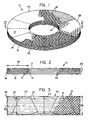
- Figure 1 is an isometric view of a friction disk according to an embodiment of the invention.
- Figure 2 is an enlarged sectional view taken along plane 2-2 of Figure 1, depicting schematically the fiber distribution therein.
- Figure 3 is a schematic depiction showing layout of arcuate sectors to be cut out of a strip or tape of a multidirectional fabric.
- Figure 4 is a plan schematic view of an embodiment of an annular shaped filamentary structure according to the invention formed from a helical tape formed of joined arcuate sectors of a multidirectional fabric.
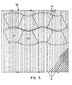
- Figure 5 is a plan view depicting a layout of arcuate sectors to be cut out from a large strip of of a a multidirectional fabric.
- Figure 6 is an exploded schematic view of an embodiment of an annular shaped filamentary structure according to the invention formed from a pair of helical tapes.
- Referring to the drawings, wherein like reference numerals designate like or corresponding parts throughout the several views, there is shown in Figures 1 and 2, a
friction disk 10 comprising astack 29 superposedannular layers 26 formed by joinder of substantially identicalarcuate sectors 20 of multidirectional fabric derived fromtows 12 of OPF cross-linked to one another by filaments 15 (Figure 2) displaced fromlayers 26 by needlepunching to consolidate and densify a preform disk similar to preformdisk 40 shown in Figure 4, the OPF having been converted to carbon fiber and further densified after needlepunching by carbon matrix deposition using conventional CVI processes. In other embodiments, the cross-linked layers may have deposited thereon a matrix of carbon, ceramic, precursor of carbon, precursor of ceramic, and mixtures of these to further bind together the cross-linked layers. Eachannular layer 26 in the embodiment shown in Figures 1 and 2 is formed of six substantially identicalarcuate sectors 20 positioned side by side. - The filaments of
tows 12 within thedisk 10 may be substantially continuous within each respectivearcuate sector 20 between the inside diameter (ID) and outside diameter (OD) cylindricalperipheral surfaces disk 10 and its flat,parallel wear faces filaments 15 that have been displaced perpendicularly to thewear faces - The
sectors 20, 20' may be cut from a narrow strip such asstrip 30 as shown in Figure 3 or a wide sheet such assheet 50 as shown in Figure 5 and joined end to end or in overlapping manner to form afibrous layer 26 of the required structural shape which may be joined to another fibrous layer by needlepunching of the stacked layers to form a fibrous preform such as an annular preform disk. Alternatively, thesectors 20, 20' may be joined end to end or in overlapping manner to form a helical fibrous tape (Figures 4, 6, 7, 8) or an annular layer (Figures 1, 2). The helical tape may be arranged to form a flat, hollow annular preform disk having a plurality of fibrous layers such as preform 40 as shown in Figure 4.Sectors 20,20' or ahelical tape 41 formed fromsectors 20, 20' may be interleaved with an additional helical fibrous tape, formed for example, by collapsing a helical hollow tubular braid as described in U.S.-A-5,217,770 to Morris and Liew. As shown in ghost lines in Figure 6, a helicalflat braid tape 61 may be interleaved withhelical turns 62 formed ofsectors 20 joined end to end or in overlapping manner. The braidedhelical tape 61 itself may be formed from one or more of side by side parallel braids which may be partially overlapped. - The fiber volume, i.e., the quantity of fiber per unit volume, which is usually expressed as a percentage with zero percent meaning that no fiber is present and one hundred percent meaning that only fiber is present, is essentially the same throughout each sector and thus any preform or disk formed exclusively from such sectors. In contrast, in preforms and disks formed from needlepunched stacked layers of curved braided filamentary material formed by bending a straight braid, the fiber volume is greater adjacent the
inner periphery 14 ofdisk 10 and adjacent theouter periphery 16 ofdisk 10, than in the remainder of thedisk 10. This variation in fiber volume is a natural result of forming an otherwise uniform straight tubular braid into a flattened annulus or helix. This naturally occurring variation in fiber volume associated with a curved braid formed by bending a straight braid can be minimized by braiding techniques described in U.S.-A-5,217,770 to Morris and Liew. - Having reference to Figure 3, the
sectors 20 having aradial width 22 are cut out from astraight braid 30 having awidth 35. Becausebraid 30 is a multidirectional fabric, as contrasted with a unidirectional fabric as described in the aforementioned patents to Lawton et al., the relative orientation of adjacent sectors is not critical. The ends ofadjacent sectors 20 may be contiguous as they are laid out and cut from braid such asbraid 30 shown in Figure 3 or tridirectionalcrosslapped fabric 50 shown in Figure 5. As shown, very little offcut waste is generated compared to known methods, including that shown and described in the above mentioned patents to Lawton et al.Adjacent sectors 20 may be laid out 180 degrees relative to one another. It is also possible to merely cut the multidirectional fabric strip into trapezoidal shaped sectors 20' having a radial width 22', which may be trimmed after assembly into an annular preform or even after carbonization or densification of the preform. Thebraid 30 in the preferred embodiment shown in Figure 3 is obtained by collapsing or flattening a straight tubular braid. In addition to the braidingmembers 31 which extend in helical paths relative to the lengthwise direction of thebraid 30, a system oflongitudinal members 34 extending in the lengthwise direction of the braid is introduced into the braid as it is formed. Theselongitudinal members 34 may be referred to as "unidirectionals". Theseunidirectionals 34 improve the dimensional stability as well as the tensile strength, compressive strength and moduli, and fiber volume of the tri-directional fabric.Unidirectionals 34 are introduced from stationary guide eyes in the braiding machine such that the unidirectionals will lie straight (without crimp) parallel to the braid axis 33 (longitudinal direction of the braid) while thehelical braid members 31 introduced by the braiding machine carriers pass over and under the unidirectionals as thebraided fabric 30 is formed.Straight braid 30 inherently has greater lateral stability than the unidirectional "fabric" of Lawton et al.Straight braid 30 may be needlepunched prior to cuttingsectors 20 therefrom to provide even greater dimensional stability of the braid itself and the sectors to be cut therefrom. - Forming some of the braid members and/or unidirectionals of different materials than are used for the remainder of the members forming the braid may benefit final mechanical or other properties, e.g. vibration damping, of the needlepunched and densified structure. Such materials could include other carbon-based and/or ceramic-based fibers. The braiding members and/or unidirectionals may be formed of staple fibers.
- In the embodiment shown in Figure 4, the
preform disk 40 comprises one or more helical turns 43 symmetrical aboutaxis 44 of afibrous tape 41 previously formed ofarcuate sectors 20 joined end to end, e.g. by sewing withthread 42. The radial width of thetape 41 generally corresponds to theradial distance 24 between theinner periphery 14 and theouter periphery 16 of the flat annulus. The included angle of eachsector 20 is such that theradial joints 45 of adjacent layers each formed of otherwise identical sectors are not aligned, e. g. sixty-seven degrees. The helical turns 43 oftape 41 are needlepunched to join them together. When finished,preform disk 40 is similar in appearance to that offriction disk 10 illustrated in Figure 1. One or more additional helically wound tapes (not shown in Figure 4) of similar or dissimilar construction, e. g. of continuous helical braid, may be interleaved withfibrous tape 41 to form a flat, hollow annular structure having a plurality of interleaved filamentary layers. The layers are joined by needlepunching which displaces filaments perpendicularly relative to the faces of the layers to cross-link the layers into an assembly. Thelongitudinal axis 46 of one of the groups of thefilaments 12 in eachsector 20 is disposed chordally relative to the arc of each respective sector and tangentially relative to the annular shapedstructure 40. Also shown in Figure 4 in ghost lines is trapezoidal sector 20' which may be trimmed to the arcuate shape ofsector 20 after manufacture oftape 41 orpreform disk 40. - Having reference to Figure 5, a sheet or strip of multidirectional fabric such as
crosslapped fabric 50 is shown.Fabric 50 is formed in known manner by needling together unidirectional webs of side by side filaments which webs are superposed such that the filaments of any unidirectional web forming the fabric cross at an angle to the filaments of any other unidirectional web forming the fabric. In the preferred embodiment illustrated, thefabric 50 consists of three layers of unidirectional webs and the angle of crossing of the filaments of any web is about sixty degrees relative to any other web forming thefabric 50. It is also possible to produce a suitable fabric using crossing layers, one of which is of parallelised staple fibers from a carding machine. Such carded layer may be formed from offcut waste fiber. - As shown in Figure 6, a
preform 60 having an axis ofsymmetry 66 is made from twohelically wound tapes turns 62 of fibrous tape formed fromsectors 20 to form a flat, hollow annular structure having a plurality of interleaved filamentary layers. The tape layers are joined by needlepunching which displaces filaments perpendicularly relative to the faces of the layers to cross-link the layers into an assembly. -
Fibrous tape 41, as shown in Figure 4, is made by sewing together withthread 42 the radial joints 45 of the abutting circumferentially spaced ends of theadjacent sectors 20 prior to needlepunching of the stacked layers. This enables handling of a plurality of end to end abuttedarcuate sectors 20 as a singlehelical tape portion 41 which can be guided into a rotary needlepunch loom such as that described in DE-A-2911762 to Dilo or WO-A-93/15250 to Lawton and Smith. Even when an apparatus such as that described in WO-A-93/15250 to Lawton and Smith is employed, presewing of the abutted sectors prevents separation of the abutting ends during needlepunching. - A suitable straight braid such as
braid 30 of Figure 3 may be formed from a plurality oftows 12, e.g. 12k OPF tow, on a conventional tubular braiding machine (not illustrated). A simplified version of a conventional Maypole-type braiding machine and its operation are illustrated in U.S.-A- 3,007,497 to Shobert. An eminently suitable braiding machine having one hundred forty-four carriers and seventy-two unidirectional positions is available from W. STEEGER GmbH & Co. of Wuppertal, Germany. - One manner of expressing the character of a braid is in terms of picks/2.54cm (picks/inch; PPI). For a straight collapsed tubular braid formed of 12k tows of OPF and having a nominal width of 17.78cm (seven inches) when flattened, the braid has from about 2.5 to 5 picks/2.54cm (ppi). PPI is a complex function of braider speed, fibrous material pull out rate, angle of pull out and width of braid, and is empirically determined. Five PPI means that five crossovers of the members being braided occur per 2.54cm (one inch) of machine direction movement. PPI is conveniently determinable manually as the braid apparatus is empirically adjusted.
- As previously stated, an optional, additional curved braid such as
curved braid 61 shown in Figure 6 may be interleaved with layers formed of sectors. A curved braid may be more accurately formed by a machine rather than manually as was previously done as described in US-A-5,217,770 to Morris et al. The machinery and manufacture of curved flattened tubular braid is described in USSN 08/149,854 filed November 10, 1993 entitled CURVED BRAID APPARATUS (now US-A- 5,417,138). - One or more layers of
fibrous sectors 20 are joined to one another and/or to one or more other fibrous layers superposed thereon by needlepunching. Preferably, thearcuate sectors 20 are needlepunched into a unitary preform structure as they are fed continuously onto a rotating support. This may be accomplished using a rotary needlepunch loom-such as that described in DE-A-2911762 to Dilo. This Dilo machine is provided with a needling head whose effective width corresponds to the radial extent of the fibrous strip or the arcuate sectors and preform being assembled. The apparatus described in the aforementioned patents to Lawton et al. may be employed; however the rotary receptacle need not have both inner and outer cylindrical walls to guide a continuous helical tape formed of sectors joined end to end; an inner or an outer cylindrical wall alone will suffice. The needling head of the apparatus shown in DE-A-2911762 to Dilo may be controlled programmed to avoid ovemeedling of the preform being made, which may occur at the inner periphery of the preform when using an apparatus such as that described in the aforementioned patents to Lawton et al. - If no rotary loom is available, joinder of one or more layers of
fibrous sectors 20 may be accomplished by arranging the fibrous sectors into one or more superposed layers in a needle penetrable mold or jig and passing the jig and layers to be assembled to and fro through a conventional needlepunch loom. This technique is more fully described in the aforementioned patents to Lawton et al. and in U.S.-A-5,217,770 to Morris and Liew. The use of such a jig is less desirable than use of a rotary needlepunch loom because the fibrous arcuate sectors can not be fed continuously onto the jig as it is passed to and fro through a conventional reciprocal needlepunch loom such as that illustrated in U.S.-A-4,790,052 to Olry. - The resulting needlepunched structure may be thereafter subjected to CVD densification in conventional manner to produce a friction disk similar in appearance to
disk 10 shown in Figure 1 having an average or bulk density of about 1.8 g/cm3. As used herein "density" is determined by weighing a specimen of known dimensions, such as that obtained by machining from the region of interest of a larger specimen, and is expressed as weight per unit volume, e.g., g/cm3. - A plurality of such densified disks made according to the invention may be machined in conventional manner and assembled to form a multidisk brake similar to that shown and described in any of U.S.-A-4,018,482; 4,878,563; and 4,613,017.
- Recycled or virgin OPF staple may be used in the manufacture of yams to be formed into the fabric or fabrics to be used in manufacture of shaped filamentary structures of the invention.
- It is preferred that the tows be of PAN fiber in its oxidized state (OPF) when subjected to all textile processes described herein. While it may be possible to produce suitable preform disks out of greige PAN fiber and thereafter oxidize such preforms in a batch method as opposed to the continuous oxidation method employed in the manufacture of oxidized PAN fiber, this is not deemed most economical, particularly because prior to oxidation the PAN fiber does not have the desired high density nor is it able to withstand the high temperature of the furnace cycles desired to be employed subsequent to formation of the preform disk.
- While the invention has been described with reference to the use of tow, it is within the invention to use yam formed of continuous filaments or staple fibers or blends of these in place of tow for any of the braiding members and any of the multidirectionals.
Claims (25)
- A method of making a multi-layered annular shaped fibrous structure (10, 40) having a radius and a thickness comprising the steps of: forming a multidirectional fabric (30, 50) having filaments (12) extending in at least two directions; cutting arcuate or trapezoidal sectors (20, 20') of an annular shape from said multidirectional fabric, each sector having a radial width (22, 22') generally corresponding to the radial width (24) of the fibrous structure to be formed; assembling the sectors (20, 20') in contiguous relationship to form an annular layer (26) having a radial width (22, 22') generally corresponding to the radial width (24) of the fibrous structure to be formed; providing a stack (29) of thus formed layers (26) of fibrous material, one layer on top of another; and needlepunching the stacked layers (26) to produce cross-linking of the layers (26) by filaments (15) displaced out of the layers (26) and extending in a direction generally perpendicular to the faces (17, 18) of the layers (26).
- The method of claim 1, wherein the multidirectional fabric (30, 50) has filaments (12) extending in three directions generally parallel to the plane defined by the fabric.
- The method of claim 2, in which the longitudinal axis (46) of one of the groups of the filaments (12) in each sector is disposed tangentially relative to the annular shaped structure (10, 40).
- The method of claim 2, in which the longitudinal axis (46) of one of the groups of the filaments in each sector (20) is disposed chordally relative to the arc of that sector.
- The method of claim 1, in which each of the sectors (20) is substantially identical.
- The method of claim 1, in which the ends of the sectors (20) forming an annular layer (26) are offset circumferentially relative to the ends of the sectors forming an immediately adjacent layer (26).
- The method of claim 1, further comprising forming said sectors (20, 20') by cutting from a braided fabric (30).
- The method of claim 7, further comprising providing a flattened straight tubular braid (30) having undirectionals (34), the braid having a width (35) generally corresponding the radial width (22, 22') of the sectors (20, 20') to be formed.
- The method of claim 1, further comprising forming a helical tape (41) by joining end to end sectors (20, 20') cut from one of braided (30) and crosslapped needlepunched fabrics (50) and needling stacked turns (43) of the tape.
- The method of claim 9, wherein the sectors (20, 20') forming the tape (41) are joined end to end by sewing (42):
- The method of claim 1, further comprising forming the multidirectional fabric in the shape of a helical tape (70) by joining a first layer (71) of end to end abutted sectors (20) cut from fibrous material selected from the group consisting of a needlepunched layer of unidirectional filaments, braided fabrics and crosslapped needlepunched fabrics with a second layer (72) of end to end abutted sectors (20) cut from fibrous material selected from the group consisting of a needlepunched layer of unidirectional filaments, braided fabrics and crosslapped needlepunched fabrics, by needlepunching the first and second layers (71, 72) forming the tape (70) and needling stacked turns of the tape.
- The method of claim 11, wherein the tape (70) is formed by needling together two coextensive layers (71, 72) each formed from sectors (20), the joints formed by the abutted ends of the first layer (71) being staggered relative to the joints formed by the abutted ends of the sectors of the second layer (72) forming the tape.
- The method of claim 1, further comprising forming the multidirectional fabric in the shape of a helical tape (80) by arranging sectors (81) cut from fibrous material selected from the group consisting of a needlepunched layer of unidirectional filaments, braided fabrics and crosslapped needlepunched fabrics in partially overlapping relationship with opposite ends of each sector (81) at opposite faces (82, 83) of the tape (80) and needlepunching the arranged sectors (81) forming the tape (80) and needlepunching stacked turns of the tape (80).
- The method of claim 1, further comprising forming the sectors (20, 20') by cutting from a crosslapped needlepunched fabric (50) that is formed by needling together unidirectional webs of side by side filaments which webs are superposed such that the filaments of any unidirectional web forming the fabric cross at an angle to any other unidirectional web forming the fabric.
- The method of claim 14, wherein the angle of crossing of the filaments of any web is about 60 degrees relative to any other web forming the crosslapped needlepunched fabric.
- The method of claim 1, further comprising the steps of stacking at least one layer (62) formed of arcuate sectors (20) formed from a multidirectional fabric with an additional fibrous layer (61).
- The method of claim 16, wherein said additional fibrous layer (61) is formed of braided tape.
- The method of claim 1, further comprising forming a flat hollow annulus (40) by helically winding a fibrous tape (41) formed of arcuate or trapezoidal sectors (20, 20') assembled end to end, the radial width (45) of the tape generally corresponding to the radial distance (24) between the inner periphery (14) and the outer periphery (16) of the flat annulus.
- The method of claim 1, wherein the sectors are formed from the group consisting of PAN fibers including OPF, carbon fibers, graphite fibers, ceramic fibers, precursors of carbon fibers and precursors of ceramic fibers, and mixtures of these.
- The method of claim 1, further including binding together the cross-linked layers by a matrix selected from the group consisting of carbon, ceramic, precursor of carbon, precursor of ceramic, and mixtures of these.
- The method of claim 1, further comprising forming said sectors (20) by cutting from a straight braided filamentary tape (30) having a width (35) generally corresponding to the width (22) of the sectors (20) to be formed, and superposing at least one filamentary layer (61) on said annular layer (26), and needlepunching the stacked layers (20,61) to produce crosslinking of the layers (26,61) by filaments (15) displaced out of the layers (26,61) and extending in a direction generally perpendicular to the faces (17,18) of the layers (26,61).
- The method of any of claims 1 to 21, in which the multi-layered annular shaped fibrous structure is a flat annulus having an inner periphery (14) and an outer periphery (16).
- A flat annular multi-layered fibrous structure manufactured according to anyone of claims 1 to 22 (10,40,60,70,80) having a radius and a thickness comprising a stack (29) of layers (26) of fibrous material, one layer on top of another, that are cross-linked to one another by filaments (15) displaced out of the layers (26) so as to extend in a direction generally perpendicular of the faces (17,18) of the layers (26), the layers (26) being formed from arcuate or trapezoidal sectors (20,20') of an annular shape from a multidirectional fabric (30,50) having filaments (12) that extend in at least two directions, each sector having a radial width (22,22') generally corresponding to the radial width (24) of the fibrous structure; the sectors (20,20') being in contiguous or overlapping relationship to form an annular or helical layer (26,41,70,80) having a radial width (22,22',45) generally corresponding to the radial width (24) of the fibrous structure.
- The structure of claim 23, further including a matrix selected from the group consisting of carbon, ceramic, precursor of carbon, precursor of ceramic, and mixtures of these binding together the cross-linked layers.
- The structure of claim 24 in the form of a friction disc.
Applications Claiming Priority (2)
| Application Number | Priority Date | Filing Date | Title |
|---|---|---|---|
| US366070 | 1994-12-29 | ||
| US08/366,070 US5546880A (en) | 1994-12-29 | 1994-12-29 | Annular filamentary structures and methods of making |
Publications (4)
| Publication Number | Publication Date |
|---|---|
| EP0721835A2 EP0721835A2 (en) | 1996-07-17 |
| EP0721835A3 EP0721835A3 (en) | 1996-11-13 |
| EP0721835B1 EP0721835B1 (en) | 2000-04-05 |
| EP0721835B2 true EP0721835B2 (en) | 2002-12-11 |
Family
ID=23441546
Family Applications (1)
| Application Number | Title | Priority Date | Filing Date |
|---|---|---|---|
| EP95120649A Expired - Lifetime EP0721835B2 (en) | 1994-12-29 | 1995-12-28 | Shaped filamentary structures and methods of making |
Country Status (5)
| Country | Link |
|---|---|
| US (1) | US5546880A (en) |
| EP (1) | EP0721835B2 (en) |
| JP (1) | JPH094661A (en) |
| CA (1) | CA2166251A1 (en) |
| DE (1) | DE69516105T3 (en) |
Cited By (3)
| Publication number | Priority date | Publication date | Assignee | Title |
|---|---|---|---|---|
| CN101297072B (en) * | 2005-10-24 | 2011-09-14 | 马塞尔-布加蒂股份有限公司 | Method for making three-dimensional fibrous annular structures |
| RU2540755C1 (en) * | 2013-12-19 | 2015-02-10 | Российская Федерация от имени которой выступает Министерство промышленности и торговли Российской Федерации (Минпромторг России) | Braided preform for manufacture of composite articles of complex shape |
| EP3325839B1 (en) | 2015-07-22 | 2021-06-09 | Freni Brembo S.p.A. | Shaped material and manufacturing method |
Families Citing this family (71)
| Publication number | Priority date | Publication date | Assignee | Title |
|---|---|---|---|---|
| US5165909A (en) * | 1984-12-06 | 1992-11-24 | Hyperion Catalysis Int'l., Inc. | Carbon fibrils and method for producing same |
| US6029327A (en) | 1994-07-25 | 2000-02-29 | The B.F. Goodrich Company | Process for forming fibrous structures with predetermined Z-fiber distributions |
| US6405417B1 (en) | 1994-07-25 | 2002-06-18 | Goodrich Corporation | Process for forming fibrous structures with predetermined Z-fiber distributions |
| US5546880A (en) † | 1994-12-29 | 1996-08-20 | The Bf Goodrich Company | Annular filamentary structures and methods of making |
| FR2735456B1 (en) * | 1995-06-19 | 1997-09-12 | Europ Propulsion | METHODS AND APPARATUS FOR MANUFACTURING COMPOSITE MATERIAL ANNULAR PARTS AND PREFORMS THEREFOR |
| FR2741634B1 (en) * | 1995-11-27 | 1998-04-17 | Europ Propulsion | PROCESS FOR THE REALIZATION OF FIBROUS PREFORMS INTENDED FOR THE MANUFACTURE OF ANNULAR PIECES IN COMPOSITE MATERIAL |
| EP0801162A1 (en) * | 1996-03-22 | 1997-10-15 | Fabricas Lucia Antonio Betere S.A. (Flabesa) | Process for personalising the hardness, resistance and durability of supporting or seating structures, a supporting or seating structure obtained and a machine for obtaining the same |
| US5758394A (en) * | 1996-12-20 | 1998-06-02 | The B.F. Goodrich Company | Rotary needling process and support for making needled fibrous structures |
| FR2759387B1 (en) * | 1997-02-12 | 1999-05-21 | Carbone Ind | REALIZATION OF ANNULAR FIBROUS PREFORM BY TAPE WINDING |
| FR2761379B1 (en) * | 1997-03-28 | 1999-07-09 | Europ Propulsion | PROCESS FOR PRODUCING ANNULAR FIBROUS STRUCTURES, PARTICULARLY FOR THE MANUFACTURE OF COMPOSITE MATERIAL PARTS |
| US6105223A (en) * | 1997-04-30 | 2000-08-22 | The B. F. Goodrich Company | Simplified process for making thick fibrous structures |
| DE19721473C2 (en) * | 1997-05-22 | 2002-11-14 | Deutsch Zentr Luft & Raumfahrt | Friction unit for frictional engagement with a counter body and method for producing such a friction unit |
| US5952075A (en) * | 1997-09-08 | 1999-09-14 | Fiberite, Inc. | Needled near netshape carbon preforms having polar woven substrates and methods of producing same |
| US6248417B1 (en) * | 1997-09-08 | 2001-06-19 | Cytec Technology Corp. | Needled near netshape carbon preforms having polar woven substrates and methods of producing same |
| US6045644A (en) * | 1998-07-24 | 2000-04-04 | Don; Jarlen | Near net-shape fabrication of friction disk ring structures |
| US7168528B1 (en) | 1999-05-11 | 2007-01-30 | Goodrich Corporation | Three run disk brake stack and method of assembly |
| US6340075B1 (en) | 1999-11-24 | 2002-01-22 | The B. F. Goodrich Company | Three run disk brake stack and method of assembly |
| GB2356642B (en) * | 1999-11-25 | 2001-12-05 | Dunlop Aerospace Ltd | Wear resistant articles |
| US6325186B1 (en) * | 2000-04-04 | 2001-12-04 | Jarlen Don | Near-net shape fabrication of friction disk ring structures |
| DE10045881A1 (en) * | 2000-09-14 | 2002-05-08 | Inventio Ag | Safety device for an elevator |
| US6691393B2 (en) | 2001-04-09 | 2004-02-17 | Honeywell International Inc. | Wear resistance in carbon fiber friction materials |
| EP1568911A1 (en) * | 2001-04-09 | 2005-08-31 | Honeywell International Inc. | Improved wear resistance in carbon fiber friction materials |
| US20040247845A1 (en) * | 2001-08-02 | 2004-12-09 | Toshio Abe | Composite material-use fiber base material |
| US20040074075A1 (en) * | 2001-11-08 | 2004-04-22 | James Mark C. | Wear resistance in carbon fiber friction materials |
| DE10251579B4 (en) * | 2002-03-08 | 2012-02-02 | Airbus Operations Gmbh | Method for producing a circumferential three-dimensional fiber reinforcement structure |
| EP1342554B1 (en) * | 2002-03-08 | 2010-02-03 | Airbus Deutschland GmbH | Method for making textile preforms from textile half-products |
| EP1342553B1 (en) * | 2002-03-08 | 2016-05-18 | Airbus Operations GmbH | Process for producing a fiber reinforced composite windowframe for airplanes and apparatus to implement the method |
| US7014806B2 (en) * | 2002-03-08 | 2006-03-21 | Airbus Deutschland Gmbh | Method for producing a three-dimensional fiber reinforced ring frame component |
| EP1473131A3 (en) * | 2003-04-30 | 2007-01-03 | Airbus Deutschland GmbH | Method for making textile preforms from textile half-products |
| JP4517334B2 (en) * | 2004-01-08 | 2010-08-04 | 株式会社Ihi | Composite material and manufacturing method thereof |
| FR2869330B1 (en) * | 2004-04-23 | 2006-07-21 | Messier Bugatti Sa | PROCESS FOR PRODUCING TWO-DIMENSIONAL HELICOIDAL FIBROUS TABLET |
| KR101300437B1 (en) | 2004-05-25 | 2013-08-26 | 코비디엔 엘피 | Vascular stenting for aneurysms |
| US20060206200A1 (en) * | 2004-05-25 | 2006-09-14 | Chestnut Medical Technologies, Inc. | Flexible vascular occluding device |
| US8617234B2 (en) | 2004-05-25 | 2013-12-31 | Covidien Lp | Flexible vascular occluding device |
| ES2607402T3 (en) | 2004-05-25 | 2017-03-31 | Covidien Lp | Flexible vascular occlusion device |
| US8628564B2 (en) | 2004-05-25 | 2014-01-14 | Covidien Lp | Methods and apparatus for luminal stenting |
| US7442443B2 (en) | 2005-05-31 | 2008-10-28 | Goodrich Corporation | Chromium-nickel stainless steel alloy article having oxide coating formed from the base metal suitable for brake apparatus |
| CA2635365C (en) * | 2005-12-29 | 2014-01-28 | Airbus Espana, S.L. | Process and tools for manufacturing composite ring frames |
| US8152833B2 (en) | 2006-02-22 | 2012-04-10 | Tyco Healthcare Group Lp | Embolic protection systems having radiopaque filter mesh |
| FR2900420B1 (en) * | 2006-04-26 | 2008-07-25 | Snecma Propulsion Solide Sa | METHOD FOR MAKING FIBROUS STRATE FOR MANUFACTURING A COMPOSITE PART PREFORM |
| US8440276B2 (en) * | 2008-02-11 | 2013-05-14 | Albany Engineered Composites, Inc. | Multidirectionally reinforced shape woven preforms for composite structures |
| US8234990B2 (en) * | 2008-07-31 | 2012-08-07 | General Electric Company | Methods for improving conformability of non-crimp fabric and contoured composite components made using such methods |
| US8074330B2 (en) * | 2008-08-13 | 2011-12-13 | Goodrich Corporation | Method and system for enabling z fiber transfer in needled preform |
| KR101886877B1 (en) * | 2009-10-01 | 2018-08-08 | 알바니 엔지니어드 콤포짓스, 인크. | Woven preform, composite, and method of making thereof |
| KR101998538B1 (en) * | 2009-10-01 | 2019-07-09 | 알바니 엔지니어드 콤포짓스, 인크. | Woven preform, composite, and method of making thereof |
| DE102010008370A1 (en) | 2010-02-17 | 2011-08-18 | Thüringisches Institut für Textil- und Kunststoff-Forschung e.V., 07407 | Process for producing a plate-shaped semifinished product made of fiber composite material |
| DE102013201303A1 (en) * | 2012-02-14 | 2013-08-14 | Continental Teves Ag & Co. Ohg | Internally ventilated automotive brake disc made of fiber composite material |
| CN102661344B (en) * | 2012-04-25 | 2014-04-09 | 中国地质大学(武汉) | Layer-shaped friction material with high intensity and low noise and preparation method thereof |
| US9114001B2 (en) | 2012-10-30 | 2015-08-25 | Covidien Lp | Systems for attaining a predetermined porosity of a vascular device |
| US9452070B2 (en) | 2012-10-31 | 2016-09-27 | Covidien Lp | Methods and systems for increasing a density of a region of a vascular device |
| US9943427B2 (en) | 2012-11-06 | 2018-04-17 | Covidien Lp | Shaped occluding devices and methods of using the same |
| US9279459B2 (en) | 2012-11-27 | 2016-03-08 | Schaeffler Technologies Gmbh & Co. Kg | Friction plate with compressed overlapping sections |
| US9045846B2 (en) * | 2012-12-05 | 2015-06-02 | Goodrich Corporation | Spiral textile and system for weaving the same |
| US9157174B2 (en) | 2013-02-05 | 2015-10-13 | Covidien Lp | Vascular device for aneurysm treatment and providing blood flow into a perforator vessel |
| CN103233323B (en) * | 2013-05-07 | 2015-09-02 | 江苏天鸟高新技术股份有限公司 | Fibrae circulares prefabricated component and preparation method thereof |
| US9719199B2 (en) * | 2014-05-23 | 2017-08-01 | Goodrich Corporation | System and method for transport of fibers to/from a circular needle-punching loom |
| WO2016023043A1 (en) * | 2014-08-08 | 2016-02-11 | Advanced Carbon Technologies, Llc | Non-woven, fracture reducing brake rotor preforms and pads |
| US9309613B1 (en) * | 2014-11-03 | 2016-04-12 | Goodrich Corporation | System and method to fabricate helical fabric |
| US11215250B2 (en) | 2015-06-10 | 2022-01-04 | Freni Brembo S.P.A. | Shaped material and manufacturing method |
| JP6443288B2 (en) | 2015-10-02 | 2018-12-26 | 株式会社豊田自動織機 | Fiber structure for fiber reinforced composite material, method for producing fiber structure for fiber reinforced composite material, and fiber reinforced composite material |
| CN105420933B (en) * | 2015-10-30 | 2020-08-28 | 天津工业大学 | Multilayer carbon cloth sewing device |
| AT518883B1 (en) * | 2016-09-27 | 2018-02-15 | Miba Frictec Gmbh | friction plate |
| FR3070696B1 (en) * | 2017-09-01 | 2019-09-13 | Safran Landing Systems | METHOD OF FORMING BY NEEDLETING AN ANNULAR TEXTILE PREFORM FROM A HELICOIDAL FIBROUS TABLET AND MACHINE FOR CARRYING OUT SAID METHOD |
| US11065009B2 (en) | 2018-02-08 | 2021-07-20 | Covidien Lp | Vascular expandable devices |
| US11065136B2 (en) | 2018-02-08 | 2021-07-20 | Covidien Lp | Vascular expandable devices |
| US10746246B2 (en) | 2018-08-27 | 2020-08-18 | Honeywell International Inc. | Segmented layer carbon fiber preform |
| DE102019209499A1 (en) * | 2019-06-28 | 2020-12-31 | Brembo Sgl Carbon Ceramic Brakes Gmbh | Internally ventilated rotor |
| US11614136B2 (en) * | 2020-01-14 | 2023-03-28 | Goodrich Corporation | Wear liner manufacturing systems and methods |
| IT202100009803A1 (en) * | 2021-04-19 | 2022-10-19 | Brembo Spa | SHAPED MATERIAL AND RELATED PRODUCTION METHOD |
| FR3133563B1 (en) * | 2022-03-21 | 2024-03-15 | Safran Landing Systems | Process for manufacturing a cylindrical fibrous blank for annular braking discs |
| CN115823151B (en) * | 2023-02-15 | 2023-06-20 | 西安超码科技有限公司 | Sandwich-structured carbon/ceramic brake disc |
Citations (2)
| Publication number | Priority date | Publication date | Assignee | Title |
|---|---|---|---|---|
| US5546880A (en) † | 1994-12-29 | 1996-08-20 | The Bf Goodrich Company | Annular filamentary structures and methods of making |
| WO1997004492A1 (en) † | 1995-07-21 | 1997-02-06 | Milstein Joseph B | Method of use of thermophotovoltaic emitter materials |
Family Cites Families (34)
| Publication number | Priority date | Publication date | Assignee | Title |
|---|---|---|---|---|
| US1610173A (en) * | 1922-06-16 | 1926-12-07 | Slade Edward | Friction disk and the method of making same |
| US2149483A (en) * | 1936-05-28 | 1939-03-07 | Raybestos Manhattan Inc | Friction element and method of making same |
| US2134744A (en) * | 1936-12-21 | 1938-11-01 | Raybestos Manhattan Inc | Friction material and method of producing same |
| US2587945A (en) * | 1947-07-01 | 1952-03-04 | Connecticut Asbestos Products | Friction disk and method of making same |
| US3007497A (en) * | 1956-01-23 | 1961-11-07 | Samuel M Shobert | Reinforced plastic rods and method of fabricating the same |
| DE1006681B (en) * | 1956-02-24 | 1957-04-18 | Jurid Werke Ag | Reinforcement insert for ring disc-shaped friction linings |
| US2930100A (en) * | 1958-07-16 | 1960-03-29 | Hunter James Machine Co | Needle loom structure |
| US3090101A (en) * | 1960-08-26 | 1963-05-21 | Albany Felt Co | Method of constructing a corrugator belt |
| US3257259A (en) * | 1964-03-25 | 1966-06-21 | Fieldcrest Mills Inc | Method of making non-woven fabrics |
| US3457962A (en) * | 1965-11-16 | 1969-07-29 | Samuel M Shobert | Golf club shaft and method of forming the same |
| US3657061A (en) * | 1966-12-13 | 1972-04-18 | Carborundum Co | Reinforced carbon and graphite bodies |
| US3772115A (en) * | 1966-12-13 | 1973-11-13 | Carborundum Co | Process for producing reinforced carbon and graphite bodies |
| US3730320A (en) * | 1971-05-12 | 1973-05-01 | Goodrich Co B F | High temperature brake disc |
| US3994762A (en) * | 1972-07-21 | 1976-11-30 | Hyfil Limited | Carbon fiber composites |
| US3936552A (en) * | 1975-02-05 | 1976-02-03 | The B. F. Goodrich Company | Nonmetallic composite friction member |
| US4018482A (en) * | 1975-06-19 | 1977-04-19 | The B. F. Goodrich Company | Rim construction for wheels having brake torque drives |
| GB1549687A (en) * | 1977-07-06 | 1979-08-08 | Dunlop Ltd | Production of carbon fibre reinforced carbon composite materials |
| AU517708B2 (en) * | 1978-01-12 | 1981-08-20 | Dunlop Limited | Carbon composite brake disc manufacture |
| JPS55101224A (en) * | 1979-01-30 | 1980-08-01 | Ichikawa Woolen Textile | Multiilayer needle felt cushion material |
| FR2506672A1 (en) * | 1981-06-02 | 1982-12-03 | Lorraine Carbone | METHOD FOR MANUFACTURING FRICTION DISCS |
| FR2557550B1 (en) * | 1983-12-28 | 1986-05-30 | Europ Propulsion | METHOD AND APPARATUS FOR THE MANUFACTURE OF THREE-DIMENSIONAL REVOLUTION STRUCTURES |
| US4790052A (en) * | 1983-12-28 | 1988-12-13 | Societe Europeenne De Propulsion | Process for manufacturing homogeneously needled three-dimensional structures of fibrous material |
| US4613017A (en) * | 1984-07-02 | 1986-09-23 | The B. F. Goodrich Company | Disk brake and method of assembly |
| US5323523A (en) * | 1986-01-28 | 1994-06-28 | Aerospace Preforms Limited | Production of shaped filamentary structures |
| US5388320A (en) * | 1987-01-27 | 1995-02-14 | Aerospace Preforms Limited | Production of shaped filamentary structures |
| GB8602003D0 (en) * | 1986-01-28 | 1986-03-05 | Lawton P G | Carbonisable fibre assembly |
| GB8700805D0 (en) * | 1987-01-15 | 1987-02-18 | Dunlop Ltd | Carbon fibre materials |
| FR2626294B1 (en) * | 1988-01-26 | 1990-07-13 | Carbone Ind | METHOD FOR MANUFACTURING A THREE-DIMENSIONAL FIBROUS STRUCTURE FOR THE LATEST REALIZATION OF A PART IN A COMPOSITE MATERIAL AND MACHINE FOR IMPLEMENTING SAME |
| GB8905006D0 (en) * | 1989-03-04 | 1989-04-19 | Scapa Group Plc | Manufacture of homogeneously needled three-dimensional structures of fibrous material |
| WO1991001397A1 (en) * | 1989-07-25 | 1991-02-07 | Dunlop Limited | Manufacture of carbon fibre preform |
| EP0546001B2 (en) * | 1990-08-31 | 2003-08-20 | Aerospace Preforms Limited | Production of shaped filamentary structures |
| US5217770A (en) * | 1991-08-15 | 1993-06-08 | The B. F. Goodrich Company | Braided shaped filamentary structures and methods of making |
| CA2077130C (en) * | 1991-09-04 | 2003-04-29 | Edward Lee Morris | Carbon fiber reinforced carbon/carbon composite and method of its manufacture |
| GB9220603D0 (en) * | 1992-09-30 | 1992-11-11 | Dunlop Ltd | Toughened carbon composite brake discs |
-
1994
- 1994-12-29 US US08/366,070 patent/US5546880A/en not_active Expired - Lifetime
-
1995
- 1995-12-28 CA CA002166251A patent/CA2166251A1/en not_active Abandoned
- 1995-12-28 DE DE69516105T patent/DE69516105T3/en not_active Expired - Fee Related
- 1995-12-28 EP EP95120649A patent/EP0721835B2/en not_active Expired - Lifetime
-
1996
- 1996-01-04 JP JP8016952A patent/JPH094661A/en active Pending
Patent Citations (2)
| Publication number | Priority date | Publication date | Assignee | Title |
|---|---|---|---|---|
| US5546880A (en) † | 1994-12-29 | 1996-08-20 | The Bf Goodrich Company | Annular filamentary structures and methods of making |
| WO1997004492A1 (en) † | 1995-07-21 | 1997-02-06 | Milstein Joseph B | Method of use of thermophotovoltaic emitter materials |
Cited By (4)
| Publication number | Priority date | Publication date | Assignee | Title |
|---|---|---|---|---|
| CN101297072B (en) * | 2005-10-24 | 2011-09-14 | 马塞尔-布加蒂股份有限公司 | Method for making three-dimensional fibrous annular structures |
| RU2540755C1 (en) * | 2013-12-19 | 2015-02-10 | Российская Федерация от имени которой выступает Министерство промышленности и торговли Российской Федерации (Минпромторг России) | Braided preform for manufacture of composite articles of complex shape |
| EP3325839B1 (en) | 2015-07-22 | 2021-06-09 | Freni Brembo S.p.A. | Shaped material and manufacturing method |
| US11649865B2 (en) | 2015-07-22 | 2023-05-16 | Brembo S.P.A. | Shaped material and manufacturing method |
Also Published As
| Publication number | Publication date |
|---|---|
| DE69516105D1 (en) | 2000-05-11 |
| CA2166251A1 (en) | 1996-06-30 |
| US5546880A (en) | 1996-08-20 |
| DE69516105T3 (en) | 2003-09-25 |
| JPH094661A (en) | 1997-01-07 |
| EP0721835B1 (en) | 2000-04-05 |
| EP0721835A2 (en) | 1996-07-17 |
| DE69516105T2 (en) | 2000-12-21 |
| EP0721835A3 (en) | 1996-11-13 |
Similar Documents
| Publication | Publication Date | Title |
|---|---|---|
| EP0721835B2 (en) | Shaped filamentary structures and methods of making | |
| EP0528336B1 (en) | Braided shaped filamentary structures and method of making | |
| US5662855A (en) | Method of making near net shaped fibrous structures | |
| US5609707A (en) | Carbon fiber reinforced carbon/carbon composite and method of its manufacture | |
| EP0910690B1 (en) | Simplified process for making thick fibrous structures | |
| US6691393B2 (en) | Wear resistance in carbon fiber friction materials | |
| US5952075A (en) | Needled near netshape carbon preforms having polar woven substrates and methods of producing same | |
| EP3211262B1 (en) | Differential needling of a carbon fiber preform | |
| JP2002541002A (en) | Cordal preform for fiber-reinforced products and method of making same | |
| US20240051256A1 (en) | Method of making a fibrous preform and a fibrous preform thus obtained | |
| WO2000050676A1 (en) | Improved needled near netshape carbon preforms having polar woven substrates and methods of producing same | |
| US20040074075A1 (en) | Wear resistance in carbon fiber friction materials | |
| JPH05269902A (en) | Manufacture of fibrous preform for producing a composite material article | |
| JPH08312699A (en) | Near-net-shaped fibrous structure and manufacture thereof | |
| EP4183569A1 (en) | Method for making a fibrous preform of carbon and/or fibres of a carbon precursor of pre-set height and preform directly formed | |
| EP4183568A1 (en) | Method for making a fibrous preform of carbon and/or fibres of a carbon precursor of pre-set height and preform directly formed | |
| EP1568911A1 (en) | Improved wear resistance in carbon fiber friction materials |
Legal Events
| Date | Code | Title | Description |
|---|---|---|---|
| PUAI | Public reference made under article 153(3) epc to a published international application that has entered the european phase |
Free format text: ORIGINAL CODE: 0009012 |
|
| AK | Designated contracting states |
Kind code of ref document: A2 Designated state(s): DE FR GB |
|
| PUAL | Search report despatched |
Free format text: ORIGINAL CODE: 0009013 |
|
| AK | Designated contracting states |
Kind code of ref document: A3 Designated state(s): DE FR GB |
|
| 17P | Request for examination filed |
Effective date: 19970301 |
|
| 17Q | First examination report despatched |
Effective date: 19971006 |
|
| GRAG | Despatch of communication of intention to grant |
Free format text: ORIGINAL CODE: EPIDOS AGRA |
|
| GRAG | Despatch of communication of intention to grant |
Free format text: ORIGINAL CODE: EPIDOS AGRA |
|
| GRAH | Despatch of communication of intention to grant a patent |
Free format text: ORIGINAL CODE: EPIDOS IGRA |
|
| GRAH | Despatch of communication of intention to grant a patent |
Free format text: ORIGINAL CODE: EPIDOS IGRA |
|
| GRAA | (expected) grant |
Free format text: ORIGINAL CODE: 0009210 |
|
| AK | Designated contracting states |
Kind code of ref document: B1 Designated state(s): DE FR GB |
|
| REF | Corresponds to: |
Ref document number: 69516105 Country of ref document: DE Date of ref document: 20000511 |
|
| ET | Fr: translation filed | ||
| PLBQ | Unpublished change to opponent data |
Free format text: ORIGINAL CODE: EPIDOS OPPO |
|
| PLBI | Opposition filed |
Free format text: ORIGINAL CODE: 0009260 |
|
| PLBF | Reply of patent proprietor to notice(s) of opposition |
Free format text: ORIGINAL CODE: EPIDOS OBSO |
|
| 26 | Opposition filed |
Opponent name: HONEYWELL INTERNATIONAL INC. Effective date: 20001208 |
|
| PLBF | Reply of patent proprietor to notice(s) of opposition |
Free format text: ORIGINAL CODE: EPIDOS OBSO |
|
| PLBF | Reply of patent proprietor to notice(s) of opposition |
Free format text: ORIGINAL CODE: EPIDOS OBSO |
|
| REG | Reference to a national code |
Ref country code: GB Ref legal event code: IF02 |
|
| PLAW | Interlocutory decision in opposition |
Free format text: ORIGINAL CODE: EPIDOS IDOP |
|
| PLAW | Interlocutory decision in opposition |
Free format text: ORIGINAL CODE: EPIDOS IDOP |
|
| RAP2 | Party data changed (patent owner data changed or rights of a patent transferred) |
Owner name: GOODRICH CORPORATION |
|
| PUAH | Patent maintained in amended form |
Free format text: ORIGINAL CODE: 0009272 |
|
| STAA | Information on the status of an ep patent application or granted ep patent |
Free format text: STATUS: PATENT MAINTAINED AS AMENDED |
|
| 27A | Patent maintained in amended form |
Effective date: 20021211 |
|
| AK | Designated contracting states |
Kind code of ref document: B2 Designated state(s): DE FR GB |
|
| ET3 | Fr: translation filed ** decision concerning opposition | ||
| PGFP | Annual fee paid to national office [announced via postgrant information from national office to epo] |
Ref country code: DE Payment date: 20070131 Year of fee payment: 12 |
|
| PG25 | Lapsed in a contracting state [announced via postgrant information from national office to epo] |
Ref country code: DE Free format text: LAPSE BECAUSE OF NON-PAYMENT OF DUE FEES Effective date: 20080701 |
|
| PGFP | Annual fee paid to national office [announced via postgrant information from national office to epo] |
Ref country code: GB Payment date: 20141224 Year of fee payment: 20 |
|
| PGFP | Annual fee paid to national office [announced via postgrant information from national office to epo] |
Ref country code: FR Payment date: 20141208 Year of fee payment: 20 |
|
| REG | Reference to a national code |
Ref country code: GB Ref legal event code: PE20 Expiry date: 20151227 |
|
| PG25 | Lapsed in a contracting state [announced via postgrant information from national office to epo] |
Ref country code: GB Free format text: LAPSE BECAUSE OF EXPIRATION OF PROTECTION Effective date: 20151227 |