EP0720893A1 - Appareil de scellement de chevilles actionné par de la poudre - Google Patents
Appareil de scellement de chevilles actionné par de la poudre Download PDFInfo
- Publication number
- EP0720893A1 EP0720893A1 EP95810773A EP95810773A EP0720893A1 EP 0720893 A1 EP0720893 A1 EP 0720893A1 EP 95810773 A EP95810773 A EP 95810773A EP 95810773 A EP95810773 A EP 95810773A EP 0720893 A1 EP0720893 A1 EP 0720893A1
- Authority
- EP
- European Patent Office
- Prior art keywords
- piston
- section
- passage opening
- cylinder
- liquid medium
- Prior art date
- Legal status (The legal status is an assumption and is not a legal conclusion. Google has not performed a legal analysis and makes no representation as to the accuracy of the status listed.)
- Granted
Links
- 238000013016 damping Methods 0.000 claims abstract description 37
- 239000007788 liquid Substances 0.000 claims description 39
- 238000000034 method Methods 0.000 claims description 16
- 230000008569 process Effects 0.000 claims description 16
- 238000006073 displacement reaction Methods 0.000 claims description 11
- 230000007423 decrease Effects 0.000 claims description 3
- 239000002360 explosive Substances 0.000 abstract description 2
- 230000000694 effects Effects 0.000 description 9
- 239000007789 gas Substances 0.000 description 9
- 238000007654 immersion Methods 0.000 description 5
- 230000008602 contraction Effects 0.000 description 3
- 230000035939 shock Effects 0.000 description 3
- 230000006866 deterioration Effects 0.000 description 2
- 239000003380 propellant Substances 0.000 description 2
- 230000008901 benefit Effects 0.000 description 1
- 230000005540 biological transmission Effects 0.000 description 1
- 238000010276 construction Methods 0.000 description 1
- 230000006735 deficit Effects 0.000 description 1
- 238000010304 firing Methods 0.000 description 1
- 230000001771 impaired effect Effects 0.000 description 1
- 230000007246 mechanism Effects 0.000 description 1
- 230000009467 reduction Effects 0.000 description 1
- 230000004044 response Effects 0.000 description 1
Images


Classifications
-
- B—PERFORMING OPERATIONS; TRANSPORTING
- B25—HAND TOOLS; PORTABLE POWER-DRIVEN TOOLS; MANIPULATORS
- B25D—PERCUSSIVE TOOLS
- B25D9/00—Portable percussive tools with fluid-pressure drive, i.e. driven directly by fluids, e.g. having several percussive tool bits operated simultaneously
-
- B—PERFORMING OPERATIONS; TRANSPORTING
- B25—HAND TOOLS; PORTABLE POWER-DRIVEN TOOLS; MANIPULATORS
- B25C—HAND-HELD NAILING OR STAPLING TOOLS; MANUALLY OPERATED PORTABLE STAPLING TOOLS
- B25C1/00—Hand-held nailing tools; Nail feeding devices
- B25C1/08—Hand-held nailing tools; Nail feeding devices operated by combustion pressure
- B25C1/10—Hand-held nailing tools; Nail feeding devices operated by combustion pressure generated by detonation of a cartridge
- B25C1/12—Hand-held nailing tools; Nail feeding devices operated by combustion pressure generated by detonation of a cartridge acting directly on the bolt
- B25C1/123—Hand-held nailing tools; Nail feeding devices operated by combustion pressure generated by detonation of a cartridge acting directly on the bolt trigger operated
-
- B—PERFORMING OPERATIONS; TRANSPORTING
- B25—HAND TOOLS; PORTABLE POWER-DRIVEN TOOLS; MANIPULATORS
- B25C—HAND-HELD NAILING OR STAPLING TOOLS; MANUALLY OPERATED PORTABLE STAPLING TOOLS
- B25C1/00—Hand-held nailing tools; Nail feeding devices
- B25C1/08—Hand-held nailing tools; Nail feeding devices operated by combustion pressure
- B25C1/10—Hand-held nailing tools; Nail feeding devices operated by combustion pressure generated by detonation of a cartridge
- B25C1/18—Details and accessories, e.g. splinter guards, spall minimisers
Definitions
- the invention relates to a powder-operated bolt-actuating device with hydropneumatic damping device with a device part designed as a guide housing for a driving piston guide and a device part designed as a handle part, which can be displaced in the setting direction against the force of a hydropneumatic damping device in the setting direction, the one device part as the receptacle of a liquid medium cylinder containing gas pressure and the other device part cooperates with a piston which can be displaced in the cylinder against the flow resistance of the liquid medium and which divides the cylinder into a front cylinder space and a rear cylinder space.
- Powder-operated setting tools have a driving piston which is driven by the expanding gases of a propellant charge and which acts on a bolt to be set.
- Devices of this type usually have a relatively large recoil. In the past, various proposals have therefore been presented to dampen this recoil and to make the device more comfortable for the operating personnel.
- a powder-operated bolt setting device which has a guide housing for driving piston guidance.
- a spring is provided between the guide housing and a handle part that is displaceable relative thereto, which is intended to absorb and dampen the recoil acting on the operating personnel during the driving-in process of the bolt.
- the damping effect of such a spring solution is only sufficient at low spring rates.
- a small spring rate requires a large spring and increased space requirements, which means that such a damping device equipped device becomes unwieldy.
- the use of a smaller spring with a higher spring rate in turn reduces the damping effect, so that the operating personnel still have a high proportion of the undesirable recoil forces.
- the reset speed is very high in such known springs, so that undesirable vibrations acting on the operating personnel also occur during the reset.
- the recoil is absorbed by the hydropneumatic damping device, which comprises a cylinder containing a liquid medium under gas pressure and a piston which can be displaced within the cylinder against the flow resistance of the liquid medium.
- the cylinder is mounted in a housing part connected to the guide part.
- a shaft connected to the piston protrudes through the cylinder and is supported on the handle part. If the handle part and the guide housing are displaced relative to one another, the displacement force is transmitted to the piston via the shaft.
- the piston divides the cylinder into a front and a rear cylinder space.
- the liquid medium pressurized when immersing or resetting the piston flows through valves from the rear to the front cylinder chamber and back.
- the valve mechanism controls the flow openings for the liquid medium in the cylinder depending on the direction of movement of the piston via throttle valves.
- the opening cross-sections of the valves are larger than when the piston is reset.
- the damping effect when the piston is reset is greater than when immersing, and the piston slowly returns to its starting position. Without this control of the opening cross-section of the valves, the piston would spring back, which can lead to undesirable vibrations which affect the operating personnel.
- the explosive expansion of the propellant gas in the device leads to extreme shock loads. Shock waves can thereby be transmitted to the damping device via the shaft.
- the throttle valves of the valve devices are exposed to great loads and can be destroyed, as a result of which the damping effect is impaired.
- the opening cross-section of the valves is no longer reduced when the piston is reset, which means that the damping is not increased and the piston can spring back.
- the object of the present invention is therefore to improve a powder-operated setting tool with a hydropneumatic damping device to the effect that there is no appreciable deterioration in the damping effect compared to the recoil occurring during the setting process over the operating life of the device.
- a springing back of the piston of the damping device after immersion should be reliably avoided.
- the setting tool should offer a high level of comfort for the operating personnel in operation, and should keep unwanted vibrations away.
- the device should have a handy design if the aforementioned requirements are met.
- a powder-operated setting tool which has the features listed in the characterizing section of patent claim 1.
- a generic powder-operated setting tool is improved in such a way that the hydropneumatic damping device is free of movable valve parts and that for the liquid medium displaced during the displacement process of the piston there is at least one passage opening which has a minimum cross section and is designed such that the liquid medium , which flows into the front cylinder space in the setting direction when the piston is immersed, has an effective flow cross section that corresponds to the minimum cross section of the passage opening, while when the piston is reset, the effective flow cross section of the liquid medium flowing into the rear cylinder space against the setting direction in the region of the passage opening is smaller than their minimum cross section.
- the throttle valve-free design of the hydropneumatic damping device has the advantage that the shock waves occurring during the setting process cannot lead to any damage to the valve device and thus to no impairment of the damping effect of the damping device.
- the inventive design of the at least one passage opening for the liquid medium flowing during the displacement of the piston from the rear cylinder space into the front and vice versa ensures that the piston can quickly dip into the cylinder in order to absorb and dampen the recoil during the setting process that, on the other hand, the return of the piston to the initial position is damped more.
- the passage opening is designed in such a way that the entire liquid medium displaced from the rear cylinder space during the plunging-in process of the piston Minimum cross section of the passage opening is available and the effective flow cross section corresponds to the minimum cross section.
- the return of the piston to its initial position is slowed down by the fact that the liquid medium flowing back into the rear cylinder chamber experiences a jet contraction due to the special design of the passage opening.
- the effective flow cross section of the medium flowing back is thus reduced in the region of the passage opening; it is up to about 40% smaller than the minimum cross section of the passage opening. This reduction in the effective flow cross section results in an increased resistance which the piston pushed back into its starting position experiences during its displacement.
- the passage opening is edged with sharp edges in the region of its minimum cross section and is designed to be expanded in the plunging direction of the piston.
- This configuration of the passage opening ensures that the effective flow cross section during the immersion process corresponds to the geometric minimum cross section of the passage opening.
- the sharp-edged border of the passage opening in the area of its minimum cross section creates a vortex in the liquid flow. The vortices contract behind the narrowest area of the passage opening. This narrows the effective flow cross-section.
- the cross section of the passage opening in the plunging direction of the piston is preferably of substantially continuous or quasi-continuous configuration.
- at least one boundary surface of the passage opening is designed to be continuously curved or to be phased in one or more stages. In this way, an essentially laminar flow of the liquid medium is ensured during the plunging process of the piston, the effective flow cross section of which corresponds to the geometric minimum cross section of the passage opening.
- vortices can already form directly behind the impact edge of the passage opening, which thereby narrow the flow cross-section in the initial area of the flow opening.
- a design variant of the invention that is simple to construct provides for one or more passage openings to be arranged in the piston or on the piston circumference.
- the passage opening is designed as an annular gap, preferably interrupted by guide webs, between the piston and the inner wall of the cylinder.
- the piston interface facing the front cylinder chamber extends essentially perpendicular to the cylinder wall and has the largest diameter.
- the diameter of the piston decreases continuously or quasi-continuously towards the rear cylinder chamber. In this way, the desired shape of the passage opening (s) is achieved, and nevertheless, due to the guide webs, the piston is reliably guided in the cylinder.
- An alternative embodiment variant of the invention provides for one or more passage openings to be arranged as a bypass in the cylinder wall.
- a front mouth of the bypass has the minimum cross section and is arranged in the front cylinder space.
- a rear mouth of the bypass has a larger cross section than the minimum cross section and is located in the rear cylinder space.
- the displacement path of the piston extends between the two mouths.
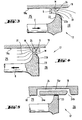
- the bolt-actuating device has a multi-part guide housing 1 connected to a unit, consisting of a front housing part 2, a rear housing part 3 and a cover 4 closing the rear housing part 3.
- a barrel 5 with a bolt guide 6 fixed to it on the front slidably mounted.
- the barrel 5 and the pin guide 6 accommodate a driving piston 7.
- a cartridge bearing 5b opens into the rear of the running bore 5a which serves to guide the driving piston 7.
- a stop screw 8, which interacts with a shoulder 5c of the barrel 5, serves to limit the displacement path of the barrel 5 and the bolt guide 6.
- the barrel 5 is displaced by a plunger 9 which is displaceably mounted in the rear housing part 3 by the force of a spring 11 into the stop position shown in FIG. 1.
- a channel 1a passing through the guide housing 1 is provided.
- An ignition device 12 is arranged in the rear housing part 3. This consists of an ignition pin 13 with an ignition lug 13a, which can protrude into the channel 1a in the setting direction.
- the firing pin 13 is traversed by a driving pin 13b, which is inserted into the displacement path of a driving shoulder 9a of the plunger 9 for the tensioning process of the ignition device 12.
- the ignition pin 13 is acted upon in the setting direction by an ignition spring 14 which, like the spring 11, is supported on the rear of the cover 4.
- an essentially laterally protruding grip part 15 is slidably mounted parallel to the barrel axis.
- a trigger 16 is arranged in the handle part 15.
- a damping device 17 is clamped between a support bearing 3a on the rear housing part 3 and a trough 15a arranged on the handle part 15.
- This consists of a cylinder 18, in the rear zone of which there is a separating piston 19. Before the separating piston 19, the cylinder volume is filled with a liquid medium 21, in particular oil.
- a prestressed gas cushion 22 is located behind the separating piston 19. The gas pressure is transmitted to the liquid medium 21 via the separating piston 19.
- a piston 23 is mounted, which projects from the cylinder 18 with a shaft 23a and is supported on the housing part 2.
- the piston 23 divides the volume available for the liquid medium into a front cylinder space 25 and a rear cylinder space, to which the separating piston 19 and the space with the prestressed gas cushion 22 adjoins.
- the liquid medium 21 under the pressure of the gas cushion 22 acts on all sides of the part of the piston 23 located in the cylinder 18.
- the rear end face of the piston 23 is larger than the front end face reduced by the cross section of the shaft 23a. This difference in area causes the piston 23 to be driven against the support bearing 3a.
- the grip part 15 is held in the position shown relative to the guide housing 1 against the setting direction, which is defined by the run-up of a grip-side stop part 15b at the outlet of a longitudinal opening 2a of the front housing part 2.
- the ignition readiness position according to FIG. 2 is achieved by pressing the bolt-setting device equipped with a cartridge 10 and a nail 20 in the bolt guide 6 against a part 28 to be fastened which rests on a component 27.
- the plunger 9 is displaced from the barrel 5 in the guide housing 1 against the force of the spring 11 against the setting direction.
- the plunger 9 also takes the ignition pin 13 against the force of the ignition spring 14 against the setting direction when the driving shoulder 9a engages on the driving pin 13b.
- the forces to be overcome in order to achieve the ignition readiness position are smaller than the response force of the damping device 17, so that the said forces can be transmitted from the handle part 15 to the guide housing 1 without these parts being mutually displaced.
- the damping device 17 is designed to absorb the recoil during the setting process and prevents the transmission of disturbing or even damaging vibrations to the operator.
- the recoil forces of the barrel 5 are transmitted to the piston 23 via the guide housing 1.
- the damping device according to the invention is equipped with throttle-free passage openings 24 for the liquid medium 21 which is pressurized during the displacement of the piston 23.
- the piston is immersed in the cylinder 18 by the recoil forces of the barrel 5, the liquid medium 21 flowing out of the cylinder space 26 behind the piston 23 into the front cylinder space 25.
- the passage openings 24 are designed such that the liquid medium 21 has the full minimum cross section of the passage openings 24 when immersed.
- the effective flow cross section S of the liquid medium 21 flowing from the rear 26 into the front cylinder chamber 25 corresponds to the minimum cross section of the passage openings 24.
- This minimum cross section and the number of Passage openings 24 are selected in such a way that the plunger 23 is immersed quickly and damped.
- the piston 23 is then returned to the initial position shown in FIG. 1 by the pressure of the gas cushion 22, as described at the beginning.
- the passage openings 24 are designed such that the effective flow cross section S of the liquid medium 21 flowing from the front 25 into the rear cylinder space 26 is smaller than the minimum diameter of the passage openings 24 the liquid medium 21 counteracts the return movement of the piston 23, whereby the damping effect is increased and the piston 23 is slowly returned to the starting position.
- the spring 11 and the ignition spring 14 also drive the other parts in the rest position.
- the operation of the damping device 17 according to the invention with specially designed passage openings 24 is shown schematically.
- the plunging process of the piston 23 is indicated by the arrow E.
- the liquid medium 21 flows from the rear cylinder space 26 through the passage opening 24 into the front cylinder space 25.
- the passage opening 24 is delimited by the cylinder wall 18a and the piston surface 23b facing it.
- the liquid medium 21 is indicated by flow lines. Due to the special design of the passage opening 24, the laminar flow essentially remains, and the effective flow cross section of the liquid medium corresponds to the minimum cross section M of the passage opening 24.
- the cross section of the passage opening 24 increases starting from the minimum cross section M in the direction of the rear cylinder space 26 continuously. This is achieved in that a boundary surface of the passage opening 24, which is also the piston surface 23b facing the cylinder wall 18a, is curved.
- Fig. 4 shows an embodiment in which the cross section of the passage opening 24 widens quasi-continuously. This is achieved in that the piston surface 23b facing the cylinder wall 18a is designed to be phased in one or more stages. In the illustrated embodiment, the piston surface 23b is phased in three stages.
- FIG. 3 shows the return movement of the piston 23 by the arrow R. The liquid medium 21 is symbolized by flow lines. During the return of the piston 23 to its starting position (FIG. 1), the liquid medium 21 displaced from the front cylinder space 25 flows through the passage opening 24 into the rear cylinder space 26.
- Vortexes form on the sharp-edged edge of the passage opening 24 facing the front cylinder space 25 W, which lead to a stralil contraction of the liquid medium 21.
- the effective flow cross section S is smaller than the minimum cross section M of the passage opening 24.
- the backflow of the liquid medium is thereby greatly restricted, as a result of which the piston 23 is only slowly returned to the starting position.
- Fig. 5 shows a similar schematic representation of another embodiment of the damping device 17.
- the passage opening 24 is provided as a bypass in the wall of the cylinder 18.
- the bypass has two openings which are connected by a channel 24c.
- a front orifice 24a is arranged in the front cylinder space 25 before the rest position of the piston 23 and a rear orifice 24b is located in the rear cylinder space 26 behind the maximum immersion position of the piston 23.
- the displacement path of the piston 23 extends between the two orifices 24a and 24b .
- the different behavior of the damping device 17 when the piston 23 is immersed or when it is reset is achieved by the different design of the orifices.
- the rear mouth 24b is preferably funnel-shaped and largely free of sharp-edged boundary areas.
- the front mouth 24a has sharp edges, at which vortices occur, which continue through the channel 24 c and lead to a jet contraction of the liquid medium flowing through.
- grooves are milled into the cylinder wall, which essentially extend over the area of the front and rear cylinder space.
- the grooves cooperate with a piston which abuts the cylinder wall on the shaft side and whose cross-section decreases continuously or quasi-continuously from the bearing region of the piston in the direction of the rear cylinder chamber.
- the powder-powered setting tool according to the invention shows no appreciable deterioration in the damping effect over the entire period of use of the tool compared to the recoil occurring during the setting process. A springing back of the piston of the damping device after immersion is reliably avoided.
- the setting tool offers the operator a high level of comfort during operation, since the operator has hardly any significant vibrations.
- the device has a handy design.
Landscapes
- Engineering & Computer Science (AREA)
- Mechanical Engineering (AREA)
- Chemical & Material Sciences (AREA)
- Combustion & Propulsion (AREA)
- Physics & Mathematics (AREA)
- Fluid Mechanics (AREA)
- Fluid-Damping Devices (AREA)
- Portable Nailing Machines And Staplers (AREA)
- Safety Valves (AREA)
- Details Of Valves (AREA)
- Lift Valve (AREA)
- Nozzles (AREA)
- Earth Drilling (AREA)
- Fertilizing (AREA)
- Catching Or Destruction (AREA)
Applications Claiming Priority (2)
| Application Number | Priority Date | Filing Date | Title |
|---|---|---|---|
| DE19500320A DE19500320A1 (de) | 1995-01-07 | 1995-01-07 | Pulverkraftbetriebenes Bolzensetzgerät |
| DE19500320 | 1995-01-07 |
Publications (2)
| Publication Number | Publication Date |
|---|---|
| EP0720893A1 true EP0720893A1 (fr) | 1996-07-10 |
| EP0720893B1 EP0720893B1 (fr) | 1998-07-29 |
Family
ID=7751099
Family Applications (1)
| Application Number | Title | Priority Date | Filing Date |
|---|---|---|---|
| EP95810773A Expired - Lifetime EP0720893B1 (fr) | 1995-01-07 | 1995-12-07 | Appareil de scellement de chevilles actionné par de la poudre |
Country Status (8)
| Country | Link |
|---|---|
| US (1) | US5653370A (fr) |
| EP (1) | EP0720893B1 (fr) |
| JP (1) | JP3451157B2 (fr) |
| KR (1) | KR100354367B1 (fr) |
| AT (1) | ATE168919T1 (fr) |
| AU (1) | AU699758B2 (fr) |
| DE (2) | DE19500320A1 (fr) |
| ES (1) | ES2119346T3 (fr) |
Cited By (1)
| Publication number | Priority date | Publication date | Assignee | Title |
|---|---|---|---|---|
| EP1025960A1 (fr) * | 1999-02-02 | 2000-08-09 | HILTI Aktiengesellschaft | Outil de scellement |
Families Citing this family (15)
| Publication number | Priority date | Publication date | Assignee | Title |
|---|---|---|---|---|
| DE19544105A1 (de) * | 1995-11-27 | 1997-05-28 | Hilti Ag | Bolzensetzgerät mit Stoßdämpfer |
| DE19831053A1 (de) * | 1998-07-13 | 2000-01-20 | Hilti Ag | Pulverkraftbetriebenes Setzgerät |
| US5992723A (en) * | 1998-08-04 | 1999-11-30 | Lee; Chung-Heng | Shaft-operated nailing tool |
| US6729356B1 (en) * | 2000-04-27 | 2004-05-04 | Endovascular Technologies, Inc. | Endovascular graft for providing a seal with vasculature |
| US6658288B1 (en) | 2000-05-05 | 2003-12-02 | Endovascular Technologies, Inc. | Apparatus and method for aiding thrombosis through the application of electric potential |
| DE10107979B4 (de) * | 2001-02-19 | 2012-12-13 | Hilti Aktiengesellschaft | Setzgerät |
| DE10251307B4 (de) * | 2002-11-04 | 2014-04-10 | Hilti Aktiengesellschaft | Brennkraftbetriebenes Setzgerät |
| DE10259567A1 (de) * | 2002-12-19 | 2004-07-01 | Hilti Ag | Brennkraftbetriebenes Setzgerät |
| DE102005000113B4 (de) * | 2005-09-13 | 2014-03-27 | Hilti Aktiengesellschaft | Setzgerät |
| CA493745A (fr) * | 2006-10-04 | 1953-06-16 | E. Glassburn William | Relais de cale jointe |
| EP2886257A1 (fr) * | 2013-12-18 | 2015-06-24 | HILTI Aktiengesellschaft | Appareil d'enfoncement |
| EP2886258A1 (fr) * | 2013-12-18 | 2015-06-24 | HILTI Aktiengesellschaft | Appareil d'enfoncement |
| EP2886260A1 (fr) * | 2013-12-19 | 2015-06-24 | HILTI Aktiengesellschaft | Appareil d'enfoncement |
| EP2923800A1 (fr) * | 2014-03-28 | 2015-09-30 | HILTI Aktiengesellschaft | Cloueur à poudre |
| CN111347375B (zh) * | 2020-02-17 | 2022-11-01 | 天津大学 | 一种液氮射钉枪装置 |
Citations (6)
| Publication number | Priority date | Publication date | Assignee | Title |
|---|---|---|---|---|
| US2574059A (en) * | 1946-04-26 | 1951-11-06 | Schneider & Cie | Hydropneumatic recuperator for guns |
| US2731636A (en) | 1952-08-20 | 1956-01-24 | Prospection & D Inv S Tech Spi | Improvements in explosively actuated fastener driving tools |
| US2966829A (en) * | 1957-05-02 | 1961-01-03 | Tannenbaum Joseph | Recoil mechanism |
| US3985061A (en) * | 1975-05-21 | 1976-10-12 | The United States Of America | Sleeve bearing for supporting reciprocating members |
| US4774873A (en) * | 1986-09-15 | 1988-10-04 | The United States Of America As Represented By The Secretary Of The Army | Sleeve recuperator |
| EP0331168A1 (fr) | 1988-03-03 | 1989-09-06 | HILTI Aktiengesellschaft | Outil à enfoncer des goujons actionné par la poudre |
Family Cites Families (4)
| Publication number | Priority date | Publication date | Assignee | Title |
|---|---|---|---|---|
| US3646757A (en) * | 1969-09-29 | 1972-03-07 | Aerpat Ag | Lock bolt placing apparatus |
| DE2843727C2 (de) * | 1978-10-06 | 1986-02-06 | Gasfeder Verwaltungsgesellschaft mbh, 7336 Uhingen | Ausziehbare Haltevorrichtung für ein Werkzeug, insbesondere Montagewerkzeug |
| US4658913A (en) * | 1982-06-03 | 1987-04-21 | Yantsen Ivan A | Hydropneumatic percussive tool |
| DE4032204C2 (de) * | 1990-10-11 | 1999-10-21 | Hilti Ag | Setzgerät für Befestigungselemente |
-
1995
- 1995-01-07 DE DE19500320A patent/DE19500320A1/de not_active Withdrawn
- 1995-12-07 DE DE59502980T patent/DE59502980D1/de not_active Expired - Lifetime
- 1995-12-07 ES ES95810773T patent/ES2119346T3/es not_active Expired - Lifetime
- 1995-12-07 AT AT95810773T patent/ATE168919T1/de not_active IP Right Cessation
- 1995-12-07 EP EP95810773A patent/EP0720893B1/fr not_active Expired - Lifetime
-
1996
- 1996-01-05 AU AU40843/96A patent/AU699758B2/en not_active Ceased
- 1996-01-05 US US08/583,368 patent/US5653370A/en not_active Expired - Lifetime
- 1996-01-05 KR KR1019960000076A patent/KR100354367B1/ko not_active IP Right Cessation
- 1996-01-08 JP JP00089296A patent/JP3451157B2/ja not_active Expired - Fee Related
Patent Citations (6)
| Publication number | Priority date | Publication date | Assignee | Title |
|---|---|---|---|---|
| US2574059A (en) * | 1946-04-26 | 1951-11-06 | Schneider & Cie | Hydropneumatic recuperator for guns |
| US2731636A (en) | 1952-08-20 | 1956-01-24 | Prospection & D Inv S Tech Spi | Improvements in explosively actuated fastener driving tools |
| US2966829A (en) * | 1957-05-02 | 1961-01-03 | Tannenbaum Joseph | Recoil mechanism |
| US3985061A (en) * | 1975-05-21 | 1976-10-12 | The United States Of America | Sleeve bearing for supporting reciprocating members |
| US4774873A (en) * | 1986-09-15 | 1988-10-04 | The United States Of America As Represented By The Secretary Of The Army | Sleeve recuperator |
| EP0331168A1 (fr) | 1988-03-03 | 1989-09-06 | HILTI Aktiengesellschaft | Outil à enfoncer des goujons actionné par la poudre |
Cited By (1)
| Publication number | Priority date | Publication date | Assignee | Title |
|---|---|---|---|---|
| EP1025960A1 (fr) * | 1999-02-02 | 2000-08-09 | HILTI Aktiengesellschaft | Outil de scellement |
Also Published As
| Publication number | Publication date |
|---|---|
| JP3451157B2 (ja) | 2003-09-29 |
| AU699758B2 (en) | 1998-12-17 |
| KR100354367B1 (ko) | 2002-12-06 |
| DE19500320A1 (de) | 1996-07-11 |
| KR960029035A (ko) | 1996-08-17 |
| JPH08229844A (ja) | 1996-09-10 |
| ATE168919T1 (de) | 1998-08-15 |
| US5653370A (en) | 1997-08-05 |
| DE59502980D1 (de) | 1998-09-03 |
| ES2119346T3 (es) | 1998-10-01 |
| EP0720893B1 (fr) | 1998-07-29 |
| AU4084396A (en) | 1996-07-18 |
Similar Documents
| Publication | Publication Date | Title |
|---|---|---|
| EP0720893B1 (fr) | Appareil de scellement de chevilles actionné par de la poudre | |
| DE102005048949B3 (de) | Schwingungsdämpfer mit verstellbarer Dämpfkraft | |
| DE1256485B (de) | Hydraulischer Stossdaempfer | |
| DE2516810B2 (de) | Mit Druckflüssigkeit betriebener Schlagapparat | |
| EP0577955A1 (fr) | Muliplicateur de pression pneumo-hydraulique | |
| DE4027021A1 (de) | Hydraulisch betriebene schlagdrehbohrvorrichtung, insbesondere zum ankerlochbohren | |
| DE10140580A1 (de) | Kolben-Zylinderaggregat mit einer geschwindigkeitsabhängigen Dämpfkraft | |
| DE69602905T2 (de) | Druckreduzierventil | |
| EP0780195A1 (fr) | Outil de scellement actionné par poudre avec une soupape de non retour pour retourner le piston d'entraînement | |
| DE69404310T2 (de) | Mündungsbremse | |
| DE60109016T2 (de) | Stossdämpfer | |
| DE2643483B2 (de) | Hydraulischer Schlagapparat | |
| EP0331168B1 (fr) | Outil à enfoncer des goujons actionné par la poudre | |
| DE1936858B2 (de) | Selbstpumpendes hydraulisches Federbein mit innerer Niveauregelung für Fahrzeuge | |
| WO1985002444A1 (fr) | Moteur pneumatique pour appareils de pulverisation de peinture, pompes a graisse et autres | |
| DE107117T1 (de) | Hydropneumatische rueckstossbremse mit energierueckgewinnung fuer artilleriegeschuetze und handfeuerwaffen. | |
| DE2258593A1 (de) | Druckgasbetaetigter zylinder mit hydraulischer kraftverstaerkung | |
| DE1099357B (de) | Axialkolbenpumpe mit Nieder- und Hochdruckteil | |
| DE647120C (de) | Durch Verdichtung eines Stroemungsmittels arbeitender Stossdaempfer | |
| DE3207995A1 (de) | Hyraulischer zylinder und kolben mit automatischem kolbenventil | |
| DE8127300U1 (de) | Spannvorrichtung | |
| WO2004040120A1 (fr) | Dispositif pour reduire la quantite de liquide qui est aspiree par une pompe d'alimentation | |
| DE4424079C1 (de) | Hydraulischer Schlaghammer | |
| DE1428010C3 (de) | Vorrichtung zur Regelung eines von einer Brennkraftmaschine angetrie benen Verdichters | |
| DE2758128C2 (de) | Vorrichtung zum Dämpfen von beim Anfahren, Anhalten und Umkehren der Bewegungsrichtung auftretenden Stößen bei hydrostatischen Antrieben |
Legal Events
| Date | Code | Title | Description |
|---|---|---|---|
| PUAI | Public reference made under article 153(3) epc to a published international application that has entered the european phase |
Free format text: ORIGINAL CODE: 0009012 |
|
| AK | Designated contracting states |
Kind code of ref document: A1 Designated state(s): AT CH DE ES FR GB IT LI |
|
| 17P | Request for examination filed |
Effective date: 19960723 |
|
| GRAG | Despatch of communication of intention to grant |
Free format text: ORIGINAL CODE: EPIDOS AGRA |
|
| GRAG | Despatch of communication of intention to grant |
Free format text: ORIGINAL CODE: EPIDOS AGRA |
|
| GRAH | Despatch of communication of intention to grant a patent |
Free format text: ORIGINAL CODE: EPIDOS IGRA |
|
| 17Q | First examination report despatched |
Effective date: 19980107 |
|
| GRAH | Despatch of communication of intention to grant a patent |
Free format text: ORIGINAL CODE: EPIDOS IGRA |
|
| GRAA | (expected) grant |
Free format text: ORIGINAL CODE: 0009210 |
|
| ITF | It: translation for a ep patent filed | ||
| AK | Designated contracting states |
Kind code of ref document: B1 Designated state(s): AT CH DE ES FR GB IT LI |
|
| REF | Corresponds to: |
Ref document number: 168919 Country of ref document: AT Date of ref document: 19980815 Kind code of ref document: T |
|
| REG | Reference to a national code |
Ref country code: CH Ref legal event code: EP |
|
| REF | Corresponds to: |
Ref document number: 59502980 Country of ref document: DE Date of ref document: 19980903 |
|
| GBT | Gb: translation of ep patent filed (gb section 77(6)(a)/1977) |
Effective date: 19980814 |
|
| REG | Reference to a national code |
Ref country code: ES Ref legal event code: FG2A Ref document number: 2119346 Country of ref document: ES Kind code of ref document: T3 |
|
| ET | Fr: translation filed | ||
| PLBE | No opposition filed within time limit |
Free format text: ORIGINAL CODE: 0009261 |
|
| STAA | Information on the status of an ep patent application or granted ep patent |
Free format text: STATUS: NO OPPOSITION FILED WITHIN TIME LIMIT |
|
| 26N | No opposition filed | ||
| PGFP | Annual fee paid to national office [announced via postgrant information from national office to epo] |
Ref country code: AT Payment date: 20001213 Year of fee payment: 6 |
|
| PGFP | Annual fee paid to national office [announced via postgrant information from national office to epo] |
Ref country code: CH Payment date: 20001215 Year of fee payment: 6 |
|
| PG25 | Lapsed in a contracting state [announced via postgrant information from national office to epo] |
Ref country code: AT Free format text: LAPSE BECAUSE OF NON-PAYMENT OF DUE FEES Effective date: 20011207 |
|
| PG25 | Lapsed in a contracting state [announced via postgrant information from national office to epo] |
Ref country code: LI Free format text: LAPSE BECAUSE OF NON-PAYMENT OF DUE FEES Effective date: 20011231 Ref country code: CH Free format text: LAPSE BECAUSE OF NON-PAYMENT OF DUE FEES Effective date: 20011231 |
|
| REG | Reference to a national code |
Ref country code: GB Ref legal event code: IF02 |
|
| REG | Reference to a national code |
Ref country code: CH Ref legal event code: PL |
|
| PG25 | Lapsed in a contracting state [announced via postgrant information from national office to epo] |
Ref country code: IT Free format text: LAPSE BECAUSE OF NON-PAYMENT OF DUE FEES Effective date: 20051207 |
|
| PGFP | Annual fee paid to national office [announced via postgrant information from national office to epo] |
Ref country code: DE Payment date: 20121114 Year of fee payment: 18 |
|
| PGFP | Annual fee paid to national office [announced via postgrant information from national office to epo] |
Ref country code: ES Payment date: 20121227 Year of fee payment: 18 Ref country code: GB Payment date: 20121205 Year of fee payment: 18 |
|
| PGFP | Annual fee paid to national office [announced via postgrant information from national office to epo] |
Ref country code: FR Payment date: 20130107 Year of fee payment: 18 |
|
| REG | Reference to a national code |
Ref country code: DE Ref legal event code: R119 Ref document number: 59502980 Country of ref document: DE |
|
| GBPC | Gb: european patent ceased through non-payment of renewal fee |
Effective date: 20131207 |
|
| REG | Reference to a national code |
Ref country code: DE Ref legal event code: R119 Ref document number: 59502980 Country of ref document: DE Effective date: 20140701 |
|
| REG | Reference to a national code |
Ref country code: FR Ref legal event code: ST Effective date: 20140829 |
|
| PG25 | Lapsed in a contracting state [announced via postgrant information from national office to epo] |
Ref country code: DE Free format text: LAPSE BECAUSE OF NON-PAYMENT OF DUE FEES Effective date: 20140701 |
|
| PG25 | Lapsed in a contracting state [announced via postgrant information from national office to epo] |
Ref country code: FR Free format text: LAPSE BECAUSE OF NON-PAYMENT OF DUE FEES Effective date: 20131231 Ref country code: GB Free format text: LAPSE BECAUSE OF NON-PAYMENT OF DUE FEES Effective date: 20131207 |
|
| REG | Reference to a national code |
Ref country code: ES Ref legal event code: FD2A Effective date: 20150327 |
|
| PG25 | Lapsed in a contracting state [announced via postgrant information from national office to epo] |
Ref country code: ES Free format text: LAPSE BECAUSE OF NON-PAYMENT OF DUE FEES Effective date: 20131208 |