EP0720693B1 - Flow-metered pumping with load compensation system and method - Google Patents
Flow-metered pumping with load compensation system and method Download PDFInfo
- Publication number
- EP0720693B1 EP0720693B1 EP94928220A EP94928220A EP0720693B1 EP 0720693 B1 EP0720693 B1 EP 0720693B1 EP 94928220 A EP94928220 A EP 94928220A EP 94928220 A EP94928220 A EP 94928220A EP 0720693 B1 EP0720693 B1 EP 0720693B1
- Authority
- EP
- European Patent Office
- Prior art keywords
- speed
- pump
- motor
- load
- pump motor
- Prior art date
- Legal status (The legal status is an assumption and is not a legal conclusion. Google has not performed a legal analysis and makes no representation as to the accuracy of the status listed.)
- Expired - Lifetime
Links
- 238000005086 pumping Methods 0.000 title claims abstract description 25
- 238000000034 method Methods 0.000 title claims description 12
- 238000005406 washing Methods 0.000 claims description 12
- 239000007788 liquid Substances 0.000 claims description 10
- 239000000126 substance Substances 0.000 claims description 8
- 238000004140 cleaning Methods 0.000 claims 5
- 230000004913 activation Effects 0.000 claims 3
- 230000001105 regulatory effect Effects 0.000 claims 2
- 230000009467 reduction Effects 0.000 abstract description 4
- 230000000694 effects Effects 0.000 abstract description 3
- 239000003570 air Substances 0.000 description 8
- 238000005259 measurement Methods 0.000 description 8
- 239000012530 fluid Substances 0.000 description 6
- 230000009977 dual effect Effects 0.000 description 5
- 238000010586 diagram Methods 0.000 description 4
- 230000001133 acceleration Effects 0.000 description 2
- 238000004891 communication Methods 0.000 description 2
- 238000005070 sampling Methods 0.000 description 2
- 239000012080 ambient air Substances 0.000 description 1
- 238000013459 approach Methods 0.000 description 1
- 238000006243 chemical reaction Methods 0.000 description 1
- 238000012937 correction Methods 0.000 description 1
- 230000003247 decreasing effect Effects 0.000 description 1
- 238000006073 displacement reaction Methods 0.000 description 1
- 230000000737 periodic effect Effects 0.000 description 1
- 230000001360 synchronised effect Effects 0.000 description 1
Images
Classifications
-
- G—PHYSICS
- G05—CONTROLLING; REGULATING
- G05D—SYSTEMS FOR CONTROLLING OR REGULATING NON-ELECTRIC VARIABLES
- G05D7/00—Control of flow
- G05D7/06—Control of flow characterised by the use of electric means
- G05D7/0617—Control of flow characterised by the use of electric means specially adapted for fluid materials
- G05D7/0629—Control of flow characterised by the use of electric means specially adapted for fluid materials characterised by the type of regulator means
- G05D7/0676—Control of flow characterised by the use of electric means specially adapted for fluid materials characterised by the type of regulator means by action on flow sources
- G05D7/0682—Control of flow characterised by the use of electric means specially adapted for fluid materials characterised by the type of regulator means by action on flow sources using a plurality of flow sources
-
- D—TEXTILES; PAPER
- D06—TREATMENT OF TEXTILES OR THE LIKE; LAUNDERING; FLEXIBLE MATERIALS NOT OTHERWISE PROVIDED FOR
- D06F—LAUNDERING, DRYING, IRONING, PRESSING OR FOLDING TEXTILE ARTICLES
- D06F39/00—Details of washing machines not specific to a single type of machines covered by groups D06F9/00 - D06F27/00
- D06F39/02—Devices for adding soap or other washing agents
- D06F39/022—Devices for adding soap or other washing agents in a liquid state
-
- F—MECHANICAL ENGINEERING; LIGHTING; HEATING; WEAPONS; BLASTING
- F04—POSITIVE - DISPLACEMENT MACHINES FOR LIQUIDS; PUMPS FOR LIQUIDS OR ELASTIC FLUIDS
- F04B—POSITIVE-DISPLACEMENT MACHINES FOR LIQUIDS; PUMPS
- F04B43/00—Machines, pumps, or pumping installations having flexible working members
- F04B43/0009—Special features
- F04B43/0081—Special features systems, control, safety measures
-
- F—MECHANICAL ENGINEERING; LIGHTING; HEATING; WEAPONS; BLASTING
- F04—POSITIVE - DISPLACEMENT MACHINES FOR LIQUIDS; PUMPS FOR LIQUIDS OR ELASTIC FLUIDS
- F04B—POSITIVE-DISPLACEMENT MACHINES FOR LIQUIDS; PUMPS
- F04B49/00—Control, e.g. of pump delivery, or pump pressure of, or safety measures for, machines, pumps, or pumping installations, not otherwise provided for, or of interest apart from, groups F04B1/00 - F04B47/00
- F04B49/06—Control using electricity
- F04B49/065—Control using electricity and making use of computers
-
- D—TEXTILES; PAPER
- D06—TREATMENT OF TEXTILES OR THE LIKE; LAUNDERING; FLEXIBLE MATERIALS NOT OTHERWISE PROVIDED FOR
- D06F—LAUNDERING, DRYING, IRONING, PRESSING OR FOLDING TEXTILE ARTICLES
- D06F33/00—Control of operations performed in washing machines or washer-dryers
- D06F33/30—Control of washing machines characterised by the purpose or target of the control
- D06F33/32—Control of operational steps, e.g. optimisation or improvement of operational steps depending on the condition of the laundry
- D06F33/37—Control of operational steps, e.g. optimisation or improvement of operational steps depending on the condition of the laundry of metering of detergents or additives
-
- F—MECHANICAL ENGINEERING; LIGHTING; HEATING; WEAPONS; BLASTING
- F04—POSITIVE - DISPLACEMENT MACHINES FOR LIQUIDS; PUMPS FOR LIQUIDS OR ELASTIC FLUIDS
- F04B—POSITIVE-DISPLACEMENT MACHINES FOR LIQUIDS; PUMPS
- F04B2203/00—Motor parameters
- F04B2203/02—Motor parameters of rotating electric motors
- F04B2203/0201—Current
-
- F—MECHANICAL ENGINEERING; LIGHTING; HEATING; WEAPONS; BLASTING
- F04—POSITIVE - DISPLACEMENT MACHINES FOR LIQUIDS; PUMPS FOR LIQUIDS OR ELASTIC FLUIDS
- F04B—POSITIVE-DISPLACEMENT MACHINES FOR LIQUIDS; PUMPS
- F04B2203/00—Motor parameters
- F04B2203/02—Motor parameters of rotating electric motors
- F04B2203/0203—Magnetic flux
-
- F—MECHANICAL ENGINEERING; LIGHTING; HEATING; WEAPONS; BLASTING
- F04—POSITIVE - DISPLACEMENT MACHINES FOR LIQUIDS; PUMPS FOR LIQUIDS OR ELASTIC FLUIDS
- F04B—POSITIVE-DISPLACEMENT MACHINES FOR LIQUIDS; PUMPS
- F04B2203/00—Motor parameters
- F04B2203/02—Motor parameters of rotating electric motors
- F04B2203/0208—Power
-
- F—MECHANICAL ENGINEERING; LIGHTING; HEATING; WEAPONS; BLASTING
- F04—POSITIVE - DISPLACEMENT MACHINES FOR LIQUIDS; PUMPS FOR LIQUIDS OR ELASTIC FLUIDS
- F04B—POSITIVE-DISPLACEMENT MACHINES FOR LIQUIDS; PUMPS
- F04B2205/00—Fluid parameters
- F04B2205/05—Pressure after the pump outlet
Definitions
- the present invention relates generally to metered pumping systems, and particularly to a constant flow pumping system using air-backed diaphragm pumps.
- Air-backed diaphragm pumps provide an economical and reliable solution for many fluid handling applications. However, they are not suitable for use in a system where a precise or highly stable flow rate is required. The flow rate of such pumps drops with increasing pressure on the pump outlet for several reasons. First, the increased load slows the motor down resulting in a reduced flow rate. Second, the unsupported regions of the pump diaphragm balloon slightly in proportion to the pressure on the outlet, reducing the effective displacement and flow rate of the pump. These diaphragm distortion-based flow rate losses are independent of motor type.
- One method of eliminating the distortion based diaphragm flow rate loss is to support the diaphragm with some incompressible liquid in a sealed chamber behind the diaphragm.
- liquid-backed pumps are inefficient and relatively expensive compared to air-backed pumps.
- a rotor vane pump can be used instead of a diaphragm pump.
- a rotor vane pump can accurately maintain a specified flow rate through varied outlet pressures.
- rotor vane pumps are very expensive.
- rotor vane pumps cannot pump fluids containing large particulates (> 50 micron) and as a result require the use of micro filters to screen any fluid that is pumped.
- Air-backed diaphragm pumps are inexpensive and can pump fluids with relatively large particulates without impairing the pump.
- the '825 patent is directed to a portable battery powered pump which provides constant mass flow of air sample through a particulate filter or vapor trap.
- the system is used for sampling ambient air where the speed of the motor is monitored by a photo-optical device.
- the speed of the motor is varied depending upon feedback received from the photo-optical speed measuring device.
- the motor current is also measured to provide a signal to indicate restricted flow.
- the measured current may also be fed back which, in combination with the motor speed signal, causes an increased speed as air flow resistance increases.
- an automatic constant air flow rate pump unit is provided for sampling air.
- the instantaneous air flow is calculated and compared with the programmed desired air flow rate.
- the motor speed is modulated in response to the controlling computer comparing the instantaneous air flow rate with the programmed rate causing the pump to approach the desired air flow rate.
- An object of the invention is to provide a low cost metered flow pumping system that provides substantially constant flow rate across a range of pump output pressures.
- Another object of the present invention is to provide a metered flow pumping system that is not sensitive to the presence fluid particulates.
- Another object of the invention is to provide a metered flow pumping system using an air-backed diaphragm pump.
- the present invention is an improved flow-metered pumping system using an air-backed diaphragm pump with load compensation.
- a variable motor speed controller is used to compensate for flow rate reduction caused by pressure effects.
- the load on the motor driving a diaphragm pump increases in proportion to the pressure on the output of the pump. This load is measured and used in a feedback loop to increase the speed of the motor.
- the gain of this feedback loop is set at such a level as to compensate for pressure induced diaphragm distortion losses and to achieve substantially constant flow rate across a range of pump output pressures.
- a flow-metered pumping system comprising:
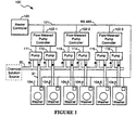
- Figure 1 is a block diagram of a washing machine system that uses the flow-metered pumping system of the instant invention to provide a constant flow rate of chemical solution to the washing machines.
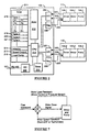
- FIG. 2 is a block diagram of the flow-metered pumping system of the instant invention.
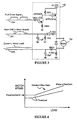
- Figure 3 depicts a pump motor drive circuit and the drive and measurement signals associated therewith.
- Figure 4 depicts a graph showing the motor speed for an air-backed diaphragm pump needed to maintain a constant flow rate for a range of motor loads.
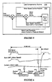
- Figure 5 is a flow chart for a dual control loop to maintain a constant flow through an air-backed diaphragm pump.
- Figure 6 is a timing diagram showing the sequence of flow control steps used in the dual control loop embodiment of the present invention.
- Figure 7 is a flow chart for an alternate control method to maintain a constant flow through a pump.
- FIG. 1 shows a washing machine system 100 utilizing metered flow pump controllers 102-1, 102-2, 102-3 of the present invention.
- the washing machine system includes washing machines 104-1 to 104-6 which receive chemical solution pumped at a measured flow rate by pumps 111-116. These metered-flow pumps are controlled by metered flow pump controllers 102-1 to 102-3.
- Each pump controller 102 can control up to two pumps. Each of the two pumps attached to one controller can feed a separate washer or they both can be attached to a single washer to provide double the maximum flow of solution to that washer.
- Washer 104-1 is shown connected to a single pump 111, which is one of two pumps controlled by metered flow controller 102-1. Pump 111 draws chemical solution from main conduit 30 and delivers the solution to washer 104-1 via feed conduit 31. Other washers in the system are connected to the pumps and main conduit in a similar manner.
- Master controller 120 coordinates the various subsystems of the washing machine system. It communicates to the pump controllers and washing machines over serial connection line 121. In the instant embodiment, this serial connection is implemented using a RS 485 communication protocol. The master controller 120 specifies desired flow rates to the metered-flow pump controllers 102 over serial connection line 121.
- FIG. 2 shows the metered flow pumping system of the instant invention including the controller 102, and two pumps 111, and 112.
- the instant invention has the capability to independently regulate two pumps but can be operated to control a single pump or multiple pumps without departing from the scope of the invention.
- Each pump 111, 112 consists of a pulse controlled permanent magnet DC motor 130, motor driver 132, and an air-backed diaphragm pump 134.
- the motor drivers 132 deliver power to motors 130 according to the signals on pulse length modulation (PLM) signal lines 234, 235 which are output from the controller 120.
- PLM pulse length modulation
- the controller 102 consists of a CPU 210 which executes software stored in a ROM 211 in conjunction with a RAM 212 for manipulating controller hardware to perform control functions.
- the ROM 211 stores control programs 214-216 and data tables 218-221.
- the data tables hold parameters used by the controller software in controlling the pump motors.
- the controller also has a timer 213 for scheduling the execution of control functions.
- A-D converters 230, 231 translate analog signals from the pump motors into digital values that are used by the CPU 210.
- the controller has output port registers 232 and 233 connected to PLM signal lines 234, 235.
- the CPU 210 writes to these registers to control the PLM signal lines 234, 235.
- the controller has I/O interface 240 sending and receiving messages to and from an outside source using the RS 485 communication protocol.
- all of the controller elements are contained within a 68HC705B5 single chip micro-controller, but they can be built using discreet components without departing from the scope of the invention.
- the controller software 214-216 instructs the CPU 210 to calculate the amount of time that the PLM signals output on lines 234, 235 should be ON in a given cycle according to the control algorithms discussed below.
- the CPU 210 programs the timer 213 to generate a signal at the specified time interval.
- the CPU 210 writes a high value to the output port corresponding to a PLM signal to turn on that PLM signal and writes a low value to the same output port to turn off the PLM signal when the timer 213 indicates that the specified time has elapsed.
- the PLM signals are periodic (8.192 ms cycle time in the instant embodiment) and control power to the pump motor.
- a PLM signal When a PLM signal is high the motor is supplied with power that causes acceleration.
- the PLM signal When the PLM signal is low the power is cut off and the motor coasts.
- the speed of a motor can be controlled by adjusting the duty cycle of the PLM signal. The more that the signal is "on" during a cycle, the faster the motor will rotate.
- each motor provides the controller with two sense signals.
- the motor back-emf signals received on lines 241, 242 are used by the controller as a measure of motor speed. Motor speed can be measured by other means such as an encoder or tachometer without departing from the scope of the invention.
- the motor current signals received on lines 243 and 244 are used by the controller as an indication of the load on each motor. Motor loading can also be measured by other means such as a torque or pressure sensor without departing from the scope of the invention.
- the measurement of the back-emf signal is synchronized with the PLM drive signal.
- the controller software reads the back-emf signal at the end of the PLM drive cycle just before the PLM signal is turned on for the next drive cycle. This timing allows the measurement of a motor's back-emf without interference from the PLM drive signal.
- the timing of the motor current signal is not critical. In the instant embodiment, the motor current is read in the middle of the PLM cycle but can be read at other points in the PLM drive cycle without effecting the operation of the invention.
- Figure 4 depicts a motor speed and motor load graph that shows relationship between motor speed and motor load for an air-backed diaphragm pump for two different flow rates.
- the load i.e., output pressure
- the motor speed must be increased in order to maintain a constant flow rate.
- the threshold load is different for different flow rates and that different positive feedback gains are needed to maintain different flow rates.
- Figure 5 shows the feedback control system implemented by the controller 210.
- the controller uses a dual feedback loop system to control the flow rate through the motor.
- the controller 210 executes a first motor speed feedback routine 215 to control motor speed.
- the controller uses a specified Speed Command value as the target motor speed. It gets a back-EMF signal from the motor that is proportional to motor speed.
- the timer is used to signal the controller when to read the back-EMF signal.
- the A-D converters are used to convert the analog back-emf signal into a digital signal for manipulation by the CPU.
- the controller uses the digital conversion of the back-EMF signal and speed command value to select the duty cycle for the PLM signal.
- An error value proportional to the difference between the actual speed (as reflected by the digitized back-EMF signal) and the speed command value is generated by the controller.
- the change in the PLM signal duty cycle is determined by multiplying the error by a proportional gain signal and adding the integral of the error with respect to time multiplied by an integral gain value. This change value is added to a "steady state" PLM duty cycle value that is determined by multiplying the speed command value by an initial gain.
- This routine is executed once during each PLM drive cycle after the back-emf has been read.
- the control software includes a second feedback loop routine 216 to adjust the speed command value used by the first feedback loop to compensate for diaphragm distortion-induced flow rate losses at high output pressures.
- the controller receives an externally sourced flow command value over the RS 485 link that specifies the target flow rate through the pump.
- the flow command value in the preferred embodiment is actually a base pump speed value which will achieve a desired flow rate if the load on the pump motor is very low.
- the controller gets a motor current signal from the motor that is proportional to the load on the motor.
- the controller uses the motor current and flow command value to select an appropriate speed command value.
- the motor current is compared to a threshold value. If the motor current is greater than the threshold, the difference between the motor current and the threshold is multiplied by a flow gain and added to the flow command value to generate a new speed command value for the motor speed feedback routine 215. As the load increases, the speed command value is increased to compensate for throughput losses caused by pressure effects.
- the following pseudocode shows the operation of the controller software implementing the second control loop:
- the positive feedback gain coefficient, FlowGain, in this routine is computed from flow and speed measurements of actual air-backed diaphragm pumps so that the flow rate of fluid through the pump remains substantially constant for a specified range of output pressures or motor loads. This routine is executed once during each PLM cycle just after the motor current signal has been read.
- the initialization routine 213 selects values for the flow gain, proportional gain and integral gain, and motor current threshold using the data tables 218-221. There is a separate table for each of these parameters. Each table consists of a sequence of flow rate / value pairs. The value paired with a flow rate is the optimized parameter value corresponding to that flow rate. These pairs are stored in the table in sequence of increasing flow rates.
- the initialization routine scans the table starting at the highest flow rate and locates the largest flow rate that is less than or equal to the new flow command. The parameter is initialized to the value corresponding this located flow rate. Using a parameter lookup table indexed according to flow rate allows the controller software to be optimized for broad range of flow rates. In the preferred embodiment, the parameters can also be down-loaded over the serial link, allowing the master controller to optimize the control software for certain situations.
- the initialization routine then ramps the motor speed up or down to the desired flow rate by increasing or decreasing speed command value by a constant amount each cycle until the target motor speed is reached. Once up to speed, the initialization routine then enables the dual loop control algorithm to control speed and compensate for load.
- the following pseudocode shows the flow of the initialization routine:
- Figure 6 is a timing diagram showing the timing relationship between the measurement of motor signals, the motor drive signals, and the software implementing the dual loop control algorithm.
- the motor drive signal When the PLM motor drive signal is high in Figure 6, the motor is receiving power that causes acceleration. When the motor drive signal is low the motor receives no power and coasts.
- the back-EMF waveform represents the back-emf of the motor driven by the PLM motor drive signal.
- the current sense waveform shows the current through the motor driven by the PLM motor drive signal.
- Motor current and back-emf measurement timing is linked to the motor drive timing because the back-emf must be sensed at the end of the drive interval just before the "on" portion of the drive waveform begins.
- the current measurements are made near the middle of the PLM drive cycle.
- the PLM motor drive signal is turned on and off according to the output of the controller timer. That same timer is used to signal the controller software to measure current and back-emf, thereby insuring that there is a precise relationship between the PLM drive signal and the motor signal measurement points.
- the motor current is read shortly after the motor drive signal is turned off.
- the load compensation routine 216 then executes and calculates a speed command value for use by the first control loop routine.
- the timer is programmed to cause a back-emf read a specified time before the start of the next PLM drive cycle.
- the speed control routine 215 is executed after the back-emf has been measured to calculate a new duty cycle value for the PLM drive signal that will be used by a counter to control the "on" portion of the subsequent PLM duty cycle.
- Figure 7 shows the flow of an alternative method of controlling the motor using only a single control loop.
- the controller implements a signal feed back loop to control motor speed.
- the controller uses a specified speed command value that is the target motor speed. It gets a signal from the motor, motor current that is proportional to the load on the motor.
- the controller uses the motor current and speed command value to select the duty cycle for the PLM motor drive signal, increasing the duty cycle of the PLM motor drive signal as the load increases.
- Controller software implementing a single control loop method has only a single feedback loop that performs both the speed control and load compensation functions.
- the sequence of instructions in the software routine is similar to the first feedback loop control routine discussed above. In this embodiment, however, the specified flow command value is used instead of a speed command value as the target motor speed.
- load compensation is implemented by directly adjusting the PLM duty cycle rather than adjusting the target motor speed.
- the following pseudocode shows the operation of the controller software implementing this feedback loop:
- This routine is executed once during each PLM cycle after motor current and back-emf have been measured.
Landscapes
- Engineering & Computer Science (AREA)
- Mechanical Engineering (AREA)
- General Engineering & Computer Science (AREA)
- General Physics & Mathematics (AREA)
- Computer Hardware Design (AREA)
- Physics & Mathematics (AREA)
- Textile Engineering (AREA)
- Automation & Control Theory (AREA)
- Control Of Positive-Displacement Pumps (AREA)
- Reciprocating Pumps (AREA)
- Details Of Flowmeters (AREA)
- Flow Control (AREA)
- External Artificial Organs (AREA)
- Control Of Non-Electrical Variables (AREA)
- Electrical Discharge Machining, Electrochemical Machining, And Combined Machining (AREA)
Applications Claiming Priority (3)
| Application Number | Priority Date | Filing Date | Title |
|---|---|---|---|
| US12716293A | 1993-09-27 | 1993-09-27 | |
| US127162 | 1993-09-27 | ||
| PCT/CA1994/000517 WO1995009305A1 (en) | 1993-09-27 | 1994-09-20 | Flow-metered pumping with load compensation system and method |
Publications (2)
| Publication Number | Publication Date |
|---|---|
| EP0720693A1 EP0720693A1 (en) | 1996-07-10 |
| EP0720693B1 true EP0720693B1 (en) | 1998-05-27 |
Family
ID=22428628
Family Applications (1)
| Application Number | Title | Priority Date | Filing Date |
|---|---|---|---|
| EP94928220A Expired - Lifetime EP0720693B1 (en) | 1993-09-27 | 1994-09-20 | Flow-metered pumping with load compensation system and method |
Country Status (12)
| Country | Link |
|---|---|
| US (1) | US5509788A (pl) |
| EP (1) | EP0720693B1 (pl) |
| JP (1) | JPH09505863A (pl) |
| AT (1) | ATE166702T1 (pl) |
| AU (1) | AU698430B2 (pl) |
| BR (1) | BR9407705A (pl) |
| CA (1) | CA2171716C (pl) |
| DE (1) | DE69410623T2 (pl) |
| ES (1) | ES2117801T3 (pl) |
| PL (1) | PL174818B1 (pl) |
| WO (1) | WO1995009305A1 (pl) |
| ZA (1) | ZA947491B (pl) |
Families Citing this family (28)
| Publication number | Priority date | Publication date | Assignee | Title |
|---|---|---|---|---|
| DE19539395A1 (de) * | 1995-10-10 | 1997-04-17 | Hako Gmbh & Co | Überwachungsvorrichtung für elektrisch angetriebene Flüssigkeitspumpen in Naßreinigungsmaschinen |
| WO1997026457A1 (de) * | 1996-01-18 | 1997-07-24 | SEZ Semiconductor-Equipment Zubehör für die Halbleiterfertigung AG | Verfahren und vorrichtung zum dosieren von fluiden |
| CA2279320A1 (en) | 1998-10-27 | 2000-04-27 | Capstone Turbine Corporation | Turbogenerator power control system |
| DE29821910U1 (de) * | 1998-12-09 | 1999-02-04 | ABEL GmbH & Co. KG, 21514 Büchen | Regelvorrichtung für eine Membranpumpe |
| EP1602386A1 (en) * | 1999-04-23 | 2005-12-07 | Ventrassist Pty Ltd | A rotary blood pump and control system therefor |
| AUPP995999A0 (en) | 1999-04-23 | 1999-05-20 | University Of Technology, Sydney | Non-contact estimation and control system |
| DE29914759U1 (de) | 1999-08-24 | 1999-12-16 | Schmidt, Uwe, Dipl.-Ing., 82024 Taufkirchen | Mehrkanaldosiersystem für Meerwasseraquaristik |
| US6353303B1 (en) * | 1999-10-19 | 2002-03-05 | Fasco Industries, Inc. | Control algorithm for induction motor/blower system |
| US6353302B1 (en) * | 1999-10-19 | 2002-03-05 | Fasco Industries, Inc. | Speed computation function for induction motor/blower systems control algorithm |
| US6353299B1 (en) * | 1999-10-19 | 2002-03-05 | Fasco Industries, Inc. | Control algorithm for brushless DC motor/blower system |
| EP1286604B1 (en) * | 2000-01-18 | 2008-04-30 | Stryker Corporation | Air filtration system including a helmet assembly with at least two air outlets to distribute air about a head of a user |
| US6542827B1 (en) | 2000-08-31 | 2003-04-01 | Wallace C. Koster | Well tending method and apparatus |
| WO2004001515A2 (en) * | 2002-05-31 | 2003-12-31 | Scott Technologies, Inc. | Speed and fluid flow controller |
| WO2003104911A2 (en) * | 2002-06-05 | 2003-12-18 | Imperial Sheet Metal Ltd. | Fluid flow balancing system |
| KR100480117B1 (ko) * | 2002-10-04 | 2005-04-07 | 엘지전자 주식회사 | 왕복동식 압축기의 스트로크 보상장치 및 방법 |
| KR100486582B1 (ko) * | 2002-10-15 | 2005-05-03 | 엘지전자 주식회사 | 왕복동식 압축기의 스트로크 검출장치 및 방법 |
| DE102004007154A1 (de) * | 2004-02-12 | 2005-08-25 | Robert Bosch Gmbh | Pumpenregelung |
| JP2006153426A (ja) * | 2004-11-08 | 2006-06-15 | Matsushita Electric Ind Co Ltd | 電動送風装置 |
| BRPI0710040B1 (pt) * | 2006-03-30 | 2017-12-26 | Diversey, Inc. | Chemical product distribution system including chamber linked to chemical product source in powder and method of distribution of liquid and powder chemical product |
| JP4425253B2 (ja) * | 2006-08-30 | 2010-03-03 | ダイキン工業株式会社 | 油圧ユニットおよび油圧ユニットにおけるモータの速度制御方法 |
| US20090053072A1 (en) * | 2007-08-21 | 2009-02-26 | Justin Borgstadt | Integrated "One Pump" Control of Pumping Equipment |
| DE102009020414A1 (de) * | 2009-05-08 | 2010-11-11 | Lewa Gmbh | Vergleichmäßigung des Förderstroms bei oszillierenden Verdrängerpumpen |
| US8459195B2 (en) | 2011-04-28 | 2013-06-11 | Michael H. IRVING | Self load sensing circuit board controller diaphragm pump |
| US9447536B2 (en) * | 2011-10-14 | 2016-09-20 | Delaware Capital Formation, Inc. | Intelligent network for chemical dispensing system |
| EP3038673B1 (en) | 2013-08-30 | 2018-10-10 | Kpr U.S., Llc | Enteral feeding pump with pump set flushing and flow compensation |
| WO2016178890A1 (en) * | 2015-05-01 | 2016-11-10 | Graco Minnesota Inc. | Adaptive flow control |
| DE102015110862B4 (de) | 2015-07-06 | 2019-03-07 | Beatrice Saier | Dosiereinrichtung zur Dosierung und Zuführung von Medien und Verfahren |
| EP3543533B1 (en) * | 2016-11-17 | 2021-03-31 | Hangzhou Sanhua Research Institute Co., Ltd. | Control system and control method |
Family Cites Families (21)
| Publication number | Priority date | Publication date | Assignee | Title |
|---|---|---|---|---|
| US2137928A (en) * | 1936-01-24 | 1938-11-22 | Baker Perkins Ltd | Automatic control of washing and other machines |
| US2197294A (en) * | 1937-07-22 | 1940-04-16 | Baker Perkins Ltd | Automatic control of washing and other machines |
| US3771333A (en) * | 1972-07-25 | 1973-11-13 | Jetronics Ind Inc | Programmable control of the injection of additives in a laundering operation |
| US3976926A (en) * | 1974-08-05 | 1976-08-24 | Hewlett-Packard Company | Digital DC motor speed control circuit |
| DE2455598A1 (de) * | 1974-11-23 | 1976-05-26 | Franz Orlita | Anlage mit einer verdraengerpumpe, insbesondere dosierpumpe, und einer steuereinrichtung zur konstanthaltung der foerdermenge pro zeiteinheit |
| US4209258A (en) * | 1978-02-14 | 1980-06-24 | Oakes W Peter | Automatic continuous mixer apparatus |
| US4241299A (en) * | 1979-04-06 | 1980-12-23 | Mine Safety Appliances Company | Control system for battery-operated pump |
| JPS5756693A (en) * | 1980-09-18 | 1982-04-05 | Toshiba Corp | Flow rate control method for pump |
| US4384825A (en) * | 1980-10-31 | 1983-05-24 | The Bendix Corporation | Personal sampling pump |
| JPS57129189A (en) * | 1981-02-04 | 1982-08-11 | Nec Corp | Control device for motor |
| JPS5986493A (ja) * | 1982-11-10 | 1984-05-18 | Fuji Electric Co Ltd | 電動機の速度制御装置 |
| US4552513A (en) * | 1983-03-07 | 1985-11-12 | Spectra-Physics, Inc. | Multiple piston pump control |
| JPS6154890A (ja) * | 1984-08-22 | 1986-03-19 | Brother Ind Ltd | Dcモ−タの制御装置 |
| JPS6229778A (ja) * | 1985-07-31 | 1987-02-07 | Tech Res Assoc Openair Coal Min Mach | 静油圧駆動制御装置 |
| US4712853A (en) * | 1986-02-27 | 1987-12-15 | Spectra-Physics, Inc. | Rapidly starting low power scan mechanism |
| US5163818A (en) * | 1990-02-05 | 1992-11-17 | Ametek, Inc. | Automatic constant air flow rate pump unit for sampling air |
| JPH0478888A (ja) * | 1990-07-20 | 1992-03-12 | Ricoh Co Ltd | 電子写真装置の感光体取付構造 |
| US5141402A (en) * | 1991-01-29 | 1992-08-25 | Vickers, Incorporated | Power transmission |
| US5262068A (en) * | 1991-05-17 | 1993-11-16 | Millipore Corporation | Integrated system for filtering and dispensing fluid having fill, dispense and bubble purge strokes |
| JPH05248363A (ja) * | 1992-03-03 | 1993-09-24 | Kayaba Ind Co Ltd | 回転ポンプの駆動装置 |
| JP3569924B2 (ja) * | 1992-03-19 | 2004-09-29 | 松下電器産業株式会社 | 流体回転装置 |
-
1994
- 1994-09-20 JP JP7510025A patent/JPH09505863A/ja active Pending
- 1994-09-20 CA CA002171716A patent/CA2171716C/en not_active Expired - Lifetime
- 1994-09-20 WO PCT/CA1994/000517 patent/WO1995009305A1/en not_active Ceased
- 1994-09-20 AT AT94928220T patent/ATE166702T1/de not_active IP Right Cessation
- 1994-09-20 PL PL94313700A patent/PL174818B1/pl unknown
- 1994-09-20 ES ES94928220T patent/ES2117801T3/es not_active Expired - Lifetime
- 1994-09-20 DE DE69410623T patent/DE69410623T2/de not_active Expired - Lifetime
- 1994-09-20 BR BR9407705A patent/BR9407705A/pt not_active IP Right Cessation
- 1994-09-20 EP EP94928220A patent/EP0720693B1/en not_active Expired - Lifetime
- 1994-09-20 AU AU77356/94A patent/AU698430B2/en not_active Expired
- 1994-09-26 ZA ZA947491A patent/ZA947491B/xx unknown
-
1995
- 1995-08-16 US US08/515,750 patent/US5509788A/en not_active Expired - Lifetime
Also Published As
| Publication number | Publication date |
|---|---|
| US5509788A (en) | 1996-04-23 |
| DE69410623D1 (de) | 1998-07-02 |
| BR9407705A (pt) | 1997-02-04 |
| ZA947491B (en) | 1995-05-15 |
| AU698430B2 (en) | 1998-10-29 |
| ES2117801T3 (es) | 1998-08-16 |
| EP0720693A1 (en) | 1996-07-10 |
| JPH09505863A (ja) | 1997-06-10 |
| PL174818B1 (pl) | 1998-09-30 |
| AU7735694A (en) | 1995-04-18 |
| CA2171716A1 (en) | 1995-04-06 |
| CA2171716C (en) | 1999-03-23 |
| ATE166702T1 (de) | 1998-06-15 |
| DE69410623T2 (de) | 1998-10-15 |
| PL313700A1 (en) | 1996-07-22 |
| WO1995009305A1 (en) | 1995-04-06 |
Similar Documents
| Publication | Publication Date | Title |
|---|---|---|
| EP0720693B1 (en) | Flow-metered pumping with load compensation system and method | |
| EP1222395B1 (en) | Method and apparatus for controlling a pump | |
| US7229474B2 (en) | Method for controlling the position of a permanent magnetically supported rotating component | |
| US4749927A (en) | Adaptive digitally controlled motor drive system and method | |
| WO2004001515A3 (en) | Speed and fluid flow controller | |
| US5295737A (en) | Electric motor-driven hydraulic pump | |
| US5996422A (en) | Buck air sampling pump flow control algorithm | |
| CA2605891A1 (en) | Controller for a motor and a method of controlling the motor | |
| US20020097992A1 (en) | Disturbance compensation control system | |
| CN109450308B (zh) | 摇摆驱动控制装置及方法 | |
| EP0684010B1 (en) | Automatic blood pressure monitor with a dual-speed control circuit for the DC inflation pump motor | |
| JP3241784B2 (ja) | モ−タ制御装置 | |
| US5191504A (en) | Control apparatus for electromagnetic device having proportional solenoid | |
| US4577164A (en) | Drive regulator utilizing variable pulse width signal | |
| JPH0766299B2 (ja) | 比例ソレノイドを有する電磁装置の制御装置 | |
| CN212155072U (zh) | 一种流量稳定可调的微型泵 | |
| KR100658770B1 (ko) | 유압 브레이크 시스템의 펌프 구동용 모터 제어장치 및 그방법 | |
| RU2157248C1 (ru) | Медицинский отсасыватель | |
| JPH0121363Y2 (pl) | ||
| KR100202689B1 (ko) | 플로팅형 엑츄에이터의 회전상태 표시방법 | |
| SU1305441A1 (ru) | Способ защиты компрессора от помпажа | |
| WO2019189298A1 (ja) | 制御装置、流体送出装置 | |
| KR20230012065A (ko) | 유체압 유닛 | |
| DE50004980D1 (de) | Pumpensteuergerät | |
| JPH02163438A (ja) | デイーゼルエンジンの燃料噴射ポンプの噴射時期制御装置 |
Legal Events
| Date | Code | Title | Description |
|---|---|---|---|
| PUAI | Public reference made under article 153(3) epc to a published international application that has entered the european phase |
Free format text: ORIGINAL CODE: 0009012 |
|
| 17P | Request for examination filed |
Effective date: 19960329 |
|
| AK | Designated contracting states |
Kind code of ref document: A1 Designated state(s): AT BE CH DE DK ES FR GB IT LI NL SE |
|
| 17Q | First examination report despatched |
Effective date: 19961111 |
|
| RAP1 | Party data changed (applicant data changed or rights of an application transferred) |
Owner name: UNILEVER PLC Owner name: UNILEVER N.V. |
|
| RBV | Designated contracting states (corrected) |
Designated state(s): AT BE CH DE DK ES FR GB IT LI NL SE |
|
| GRAG | Despatch of communication of intention to grant |
Free format text: ORIGINAL CODE: EPIDOS AGRA |
|
| GRAG | Despatch of communication of intention to grant |
Free format text: ORIGINAL CODE: EPIDOS AGRA |
|
| GRAG | Despatch of communication of intention to grant |
Free format text: ORIGINAL CODE: EPIDOS AGRA |
|
| GRAH | Despatch of communication of intention to grant a patent |
Free format text: ORIGINAL CODE: EPIDOS IGRA |
|
| GRAH | Despatch of communication of intention to grant a patent |
Free format text: ORIGINAL CODE: EPIDOS IGRA |
|
| GRAA | (expected) grant |
Free format text: ORIGINAL CODE: 0009210 |
|
| AK | Designated contracting states |
Kind code of ref document: B1 Designated state(s): AT BE CH DE DK ES FR GB IT LI NL SE |
|
| PG25 | Lapsed in a contracting state [announced via postgrant information from national office to epo] |
Ref country code: BE Free format text: LAPSE BECAUSE OF FAILURE TO SUBMIT A TRANSLATION OF THE DESCRIPTION OR TO PAY THE FEE WITHIN THE PRESCRIBED TIME-LIMIT Effective date: 19980527 Ref country code: AT Free format text: LAPSE BECAUSE OF FAILURE TO SUBMIT A TRANSLATION OF THE DESCRIPTION OR TO PAY THE FEE WITHIN THE PRESCRIBED TIME-LIMIT Effective date: 19980527 |
|
| REF | Corresponds to: |
Ref document number: 166702 Country of ref document: AT Date of ref document: 19980615 Kind code of ref document: T |
|
| REG | Reference to a national code |
Ref country code: CH Ref legal event code: EP |
|
| REF | Corresponds to: |
Ref document number: 69410623 Country of ref document: DE Date of ref document: 19980702 |
|
| REG | Reference to a national code |
Ref country code: CH Ref legal event code: NV Representative=s name: E. BLUM & CO. PATENTANWAELTE |
|
| REG | Reference to a national code |
Ref country code: ES Ref legal event code: FG2A Ref document number: 2117801 Country of ref document: ES Kind code of ref document: T3 |
|
| ITF | It: translation for a ep patent filed | ||
| PG25 | Lapsed in a contracting state [announced via postgrant information from national office to epo] |
Ref country code: DK Free format text: LAPSE BECAUSE OF FAILURE TO SUBMIT A TRANSLATION OF THE DESCRIPTION OR TO PAY THE FEE WITHIN THE PRESCRIBED TIME-LIMIT Effective date: 19980827 |
|
| ET | Fr: translation filed | ||
| PLBE | No opposition filed within time limit |
Free format text: ORIGINAL CODE: 0009261 |
|
| STAA | Information on the status of an ep patent application or granted ep patent |
Free format text: STATUS: NO OPPOSITION FILED WITHIN TIME LIMIT |
|
| 26N | No opposition filed | ||
| REG | Reference to a national code |
Ref country code: GB Ref legal event code: IF02 |
|
| NLS | Nl: assignments of ep-patents |
Owner name: DIVERSEY IP INTERNATIONAL BV |
|
| REG | Reference to a national code |
Ref country code: CH Ref legal event code: PUE Owner name: UNILEVER N.V. TRANSFER- DIVERSEY IP INTERNATIONAL |
|
| REG | Reference to a national code |
Ref country code: GB Ref legal event code: 732E |
|
| REG | Reference to a national code |
Ref country code: FR Ref legal event code: TP |
|
| REG | Reference to a national code |
Ref country code: CH Ref legal event code: PFA Owner name: DIVERSEY IP INTERNATIONAL BV Free format text: DIVERSEY IP INTERNATIONAL BV#WORLD HEADQUARTERS TOWER B, 8TH FLOOR SCHIPHOL BOULEVARD 209#1118 BH LUCHTHAVEN SCHIPHOL AIRPORT (NL) -TRANSFER TO- DIVERSEY IP INTERNATIONAL BV#WORLD HEADQUARTERS TOWER B, 8TH FLOOR SCHIPHOL BOULEVARD 209#1118 BH LUCHTHAVEN SCHIPHOL AIRPORT (NL) |
|
| PGFP | Annual fee paid to national office [announced via postgrant information from national office to epo] |
Ref country code: CH Payment date: 20100930 Year of fee payment: 17 |
|
| PGFP | Annual fee paid to national office [announced via postgrant information from national office to epo] |
Ref country code: SE Payment date: 20100929 Year of fee payment: 17 |
|
| REG | Reference to a national code |
Ref country code: CH Ref legal event code: PL |
|
| REG | Reference to a national code |
Ref country code: SE Ref legal event code: EUG |
|
| PG25 | Lapsed in a contracting state [announced via postgrant information from national office to epo] |
Ref country code: LI Free format text: LAPSE BECAUSE OF NON-PAYMENT OF DUE FEES Effective date: 20110930 Ref country code: CH Free format text: LAPSE BECAUSE OF NON-PAYMENT OF DUE FEES Effective date: 20110930 |
|
| REG | Reference to a national code |
Ref country code: NL Ref legal event code: PLEX Effective date: 20120724 |
|
| PG25 | Lapsed in a contracting state [announced via postgrant information from national office to epo] |
Ref country code: SE Free format text: LAPSE BECAUSE OF NON-PAYMENT OF DUE FEES Effective date: 20110921 |
|
| PGFP | Annual fee paid to national office [announced via postgrant information from national office to epo] |
Ref country code: DE Payment date: 20130927 Year of fee payment: 20 Ref country code: NL Payment date: 20130926 Year of fee payment: 20 Ref country code: ES Payment date: 20130926 Year of fee payment: 20 |
|
| PGFP | Annual fee paid to national office [announced via postgrant information from national office to epo] |
Ref country code: FR Payment date: 20130919 Year of fee payment: 20 Ref country code: GB Payment date: 20130927 Year of fee payment: 20 |
|
| PGFP | Annual fee paid to national office [announced via postgrant information from national office to epo] |
Ref country code: IT Payment date: 20130924 Year of fee payment: 20 |
|
| REG | Reference to a national code |
Ref country code: DE Ref legal event code: R071 Ref document number: 69410623 Country of ref document: DE |
|
| REG | Reference to a national code |
Ref country code: NL Ref legal event code: V4 Effective date: 20140920 |
|
| REG | Reference to a national code |
Ref country code: GB Ref legal event code: PE20 Expiry date: 20140919 |
|
| PG25 | Lapsed in a contracting state [announced via postgrant information from national office to epo] |
Ref country code: DE Free format text: LAPSE BECAUSE OF EXPIRATION OF PROTECTION Effective date: 20140923 |
|
| PG25 | Lapsed in a contracting state [announced via postgrant information from national office to epo] |
Ref country code: GB Free format text: LAPSE BECAUSE OF EXPIRATION OF PROTECTION Effective date: 20140919 |
|
| REG | Reference to a national code |
Ref country code: ES Ref legal event code: FD2A Effective date: 20150108 |
|
| PG25 | Lapsed in a contracting state [announced via postgrant information from national office to epo] |
Ref country code: ES Free format text: LAPSE BECAUSE OF EXPIRATION OF PROTECTION Effective date: 20140921 |