EP0720008B1 - Fahrzeugaufpralldatengenerator - Google Patents
Fahrzeugaufpralldatengenerator Download PDFInfo
- Publication number
- EP0720008B1 EP0720008B1 EP95309081A EP95309081A EP0720008B1 EP 0720008 B1 EP0720008 B1 EP 0720008B1 EP 95309081 A EP95309081 A EP 95309081A EP 95309081 A EP95309081 A EP 95309081A EP 0720008 B1 EP0720008 B1 EP 0720008B1
- Authority
- EP
- European Patent Office
- Prior art keywords
- crash
- vehicle
- frequency domain
- domain signal
- acceleration signals
- Prior art date
- Legal status (The legal status is an assumption and is not a legal conclusion. Google has not performed a legal analysis and makes no representation as to the accuracy of the status listed.)
- Expired - Lifetime
Links
- 230000001133 acceleration Effects 0.000 claims description 36
- 238000000034 method Methods 0.000 claims description 26
- 238000001914 filtration Methods 0.000 claims description 13
- 230000001131 transforming effect Effects 0.000 claims description 11
- 239000002131 composite material Substances 0.000 claims description 8
- 238000012360 testing method Methods 0.000 description 14
- 238000004519 manufacturing process Methods 0.000 description 6
- 238000010304 firing Methods 0.000 description 5
- 230000004888 barrier function Effects 0.000 description 3
- 230000018109 developmental process Effects 0.000 description 3
- 238000001228 spectrum Methods 0.000 description 3
- 238000010200 validation analysis Methods 0.000 description 3
- 238000013461 design Methods 0.000 description 2
- 238000004088 simulation Methods 0.000 description 2
- 230000033772 system development Effects 0.000 description 2
- 230000003750 conditioning effect Effects 0.000 description 1
- 238000009863 impact test Methods 0.000 description 1
- 230000003116 impacting effect Effects 0.000 description 1
Images


Classifications
-
- G—PHYSICS
- G01—MEASURING; TESTING
- G01M—TESTING STATIC OR DYNAMIC BALANCE OF MACHINES OR STRUCTURES; TESTING OF STRUCTURES OR APPARATUS, NOT OTHERWISE PROVIDED FOR
- G01M17/00—Testing of vehicles
- G01M17/007—Wheeled or endless-tracked vehicles
- G01M17/0078—Shock-testing of vehicles
Definitions
- the present invention relates in general to testing of transportation vehicles, and more specifically to generating realistic crash data sets from other crash data sets without the expense of running another crash test.
- crash testing facilitates the design, validation, and testing of occupant restraint and other crash protection systems.
- government regulations require extensive impact testing of vehicles.
- an automotive manufacturer may conduct hundreds of vehicle crash tests each year.
- Accelerometers in a test vehicle measure instantaneous acceleration at various locations within the vehicle during a crash.
- the accelerometer signals are each recorded separately using a data acquisition system.
- Many vehicles of an identical model are typically tested at various speeds and crash modes. Examples of crash modes are head on-collision with a barrier, slanted impact with a barrier, offset impact with another vehicle, and head on-collision with a pole.
- Crash testing of a single vehicle model typically includes more than one crash test at the same speed and same crash mode.
- Accelerometers are used as crash sensors in production vehicles for deploying airbags, for example. Recorded data sets from crash tests provide information allowing development of a deployment procedure or algorithm used in a microprocessor to detect an occurrence of acceleration corresponding to impacts of such a type and severity that an airbag should be inflated. The microprocessor sends a firing signal to the airbag when it detects an acceleration corresponding to such an impact. The deployment procedure is developed for recognising these events based on the data sets collected during crash testing of prototype vehicles. The crash data sets are collected from an accelerometer mounted at the same location within the prototype vehicle as the location where the production accelerometer will be mounted.
- the present invention has the advantage of creating realistic data sets for system development and validation of a crash sensor that accurately simulates a crash of a vehicle without requiring an additional crash test.
- the present invention provides a method of obtaining crash data from vehicle crashes wherein first acceleration signals are recorded during a crash of a first vehicle and second acceleration signals are recorded during a crash of a second vehicle.
- a first frequency domain signal is generated by filtering and transforming the first acceleration signals, the first frequency domain signal being substantially limited to frequencies below a predetermined cutoff frequency.
- a second frequency domain signal is generated by filtering and transforming the second acceleration signals, the second frequency domain signal being substantially limited to frequencies above the predetermined cutoff frequency.
- the first frequency domain signal and the second frequency domain signal are added to produce a composite signal.
- the composite signal is inverse transformed to generate hybrid crash data having characteristics of both of the crashes of the first vehicle and the second vehicle.
- a corresponding apparatus is as set out in claim 9.
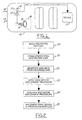
- FIG. 1 shows a vehicle 10 including a passive restraint module 11 having an accelerometer block 12 and a control block 13.
- passive restraint module 11 controls an airbag firing unit 14 mounted in steering column 15, for example.
- module 11 sends a firing signal to module 14, an airbag is inflated to the position shown at 16.
- Accelerometer block 12 preferably includes both an accelerometer and a signal conditioning circuit, such as a lowpass filter for providing instantaneous acceleration signals to control block 13.
- a signal conditioning circuit such as a lowpass filter for providing instantaneous acceleration signals to control block 13.
- the instantaneous acceleration signal from accelerometer block 12 is provided to an on-board data acquisition system (ODAS) 17.
- ODAS 17 records about 250 milliseconds of instantaneous acceleration data.
- the recorded data has a frequency spectrum from 0 Hz to about 4 kHz.
- the crashes are conducted in various crash modes according to different angles of impact and point of impact as shown by arrows 18 and 19, with various types of impacting objects such as barriers, poles, and other vehicles, and at various impact speeds.
- Figure 2 illustrates a procedure for deriving a deployment procedure used in control block 13 to detect whether an impact event is one in which a passive restraint should be deployed.
- prototype vehicles are designed and manufactured having a substantially identical structural form and that are representative of the structure and structural strength of the final production vehicles.
- the prototype vehicles are crashed in a plurality of modes and at a plurality of speeds while an on-board data acquisition system records data from the accelerometer in the form of instantaneous acceleration signals.
- the signals are digitised for storage as a plurality of data sets, each set corresponding to signals from one accelerometer during one crash at a particular crash mode and speed.
- step 23 the data sets are applied to an initial deployment procedure that may be derived empirically (such as a deployment procedure from a similar model vehicle).
- step 24 the performance of the initial deployment procedure in response to the data sets is evaluated and the deployment procedure is refined as necessary to provide desired results of either firing an airbag or not firing an airbag as appropriate depending on the crash data applied.
- the generation of data sets in step 22 includes the generation of more data sets than there are crashes of prototype vehicles, using the present invention as further described in Figure 3.
- two data sets are obtained for purposes of generating a new data set.
- the two data sets selected may preferably be from first and second crashes at substantially identical crash modes and at substantially the same speed. It is desirable that the crash modes be identical or similar so that the instantaneous acceleration signals are gathered representative of the same vehicle components crushing during a crash. It is helpful if the two data sets were obtained at about the same speed so that the same components are crushing at about the same time in the two data sets. Nevertheless, useful data sets may be generated even when the crash modes and speeds are not substantially the same.
- the present invention combines the two data sets in a manner to produce a new crash data set which contains different acceleration peaks while retaining the overall characteristics of the original crash data.
- the first data set is low-pass filtered using a predetermined upper cutoff frequency of about 60 Hz.
- the second data set is high-pass filtered using a lower cutoff frequency of about 60 Hz.
- the first and second filtered data sets are Fourier transformed into the frequency domain in step 33.
- step 34 the two Fourier transforms are added to obtain a single Fourier transform and an inverse Fourier transform is applied to the sum in step 35 to generate the new data set.
- the Fourier transforms of step 33 could be conducted prior to the filtering in steps 31 and 32. In either embodiment, first and second frequency domain signals are derived prior to adding together the Fourier transforms.
- a cutoff frequency for dividing the portions of the first and second data sets by filtering is selected at about 60 Hz because it has been found empirically that 60 Hz is about the upper limit of a base signal in the instantaneous acceleration signal that is more consistent from crash to crash than is a higher frequency signal beginning at about 60 Hz and extending up to the maximum frequency used in the deployment procedure (typically about 300 Hz). With an upper cutoff frequency of about 300 Hz, it follows from Nyquist's theorem that the recorded data signals during crashes must extend up to at least 600 Hz. Applicants have recorded instantaneous acceleration signals with an upper cutoff frequency of about 4 kHz and have generated new data sets from the recorded signals using an upper cutoff frequency of about 1 kHz.
- Figure 4 illustrates an apparatus for practising the present invention.
- a first data set is coupled into a lowpass filter 40 providing a lowpass filtered output to a fast Fourier transform (FFT) block 41.
- the transformed output in the frequency domain is coupled to one input of a summer 42.
- the second data set is coupled into a highpass filter 43 providing a highpass filtered output to a fast Fourier transform (FFT) block 44.
- a second frequency domain signal from FFT 41 is coupled to a second input of summer 42.
- Filters 40 and 43 can be implemented using FIR Butterworth filters, for example.
- Summer 42 produces a composite signal consisting of the sum of the first and second frequency domain signals.
- the composite signal is provided to inverse fast Fourier transform block 45 which produces a new data set signal in the time domain.
- the new data set characterises a hybrid crash data that has characteristics of both of the first and second vehicle crashes but is different from either one.
- the new data is realistic of an actual crash and can be used in developing crash protection components or otherwise studying crash events for any purpose.
- the upper cutoff frequency of LPF 40 and the lower cutoff frequency of HPF 43 in Figure 4 each correspond to about 60 Hz.
- three or more original crash data sets may be combined to form a new data set.
- one crash data set would provide the base signal through a lowpass filter having an upper cutoff of 60 Hz, thereby providing the base signal for the new crash data set.
- the remaining two or more original data sets would be split over the frequency spectrum of the highpass filter thereby generating yet another distinct hybrid crash data set which provides a realistic simulation of a crash.
- the highpass filtered data is statistically varied in generating yet another new data set.
- statistical variation is achieved by adding a randomised signal having a random value within predetermined limits to the original signal.
- the statistically varied upper frequency signal could even be from the same crash as provides the lower frequency base signals.
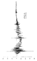
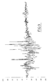
- Figure 5 shows an original crash data set from a first crash at a particular crash mode and crash speed. Acceleration peaks in the data set are utilised by a deployment procedure to recognise a crash where an airbag should be deployed.
- Figure 6 illustrates a second data set obtained from a crash of a second vehicle in the same crash mode and crash speed as in Figure 5.
- the variation in data between Figures 5 and 6 can be seen.
- a deployment procedure should nevertheless recognise both as an event where deployment of an airbag should be performed, for example.
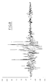
- Figure 7 plots the data set of Figure 5 after lowpass filtering with an upper cutoff frequency of 60 Hz.
- Figure 7 corresponds to the base signal within the crash data.
- Figure 8 shows the data set of Figure 6 after highpass filtering with a lower cutoff frequency of 60 Hz and an upper cutoff frequency of 1 kHz. This upper frequency region is where the greatest variation occurs from crash to crash.
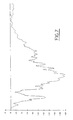
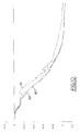
- Figure 10 plots velocity during a crash corresponding to the data sets of Figures 5, 6, and 9.
- the resulting velocity shows the similarity of the new crash data to the original crash data.
- Line 50 represents the velocity during the first vehicle crash and line 51 represents velocity during the second vehicle crash.
- Line 52 shows velocity corresponding to the hybrid crash data obtained from the first and second crashes. Line 52 follows a baseline similar to line 50 and has a higher frequency appearance more closely resembling line 51.
- the hybrid crash data produces a realistic simulation of a crash and is useful in the design and development of a crash sensor as described above.
Landscapes
- Physics & Mathematics (AREA)
- General Physics & Mathematics (AREA)
- Air Bags (AREA)
Claims (11)
- Verfahren zur Erzielung von Kollisionsdaten aus Fahrzeugaufprallversuchen, folgende Schritte aufweisend:Aufzeichnen erster Beschleunigungssignale während eines Aufprallversuches eines ersten Fahrzeuges;Aufzeichnen zweiter Beschleunigungssignale während eines Aufprallversuches eines zweiten Fahrzeuges;Erzeugen eines ersten Frequenzbereichssignales durch Filterung und Umrechnung der besagten ersten Beschleunigungssignale, wobei besagtes erstes Frequenzbereichssignal im wesentlichen auf Frequenzen unter einer vorgegebenen Grenzfrequenz beschränkt ist;Erzeugen eines zweiten Frequenzbereichssignales durch Filterung und Umrechnung der besagten zweiten Beschleunigungssignale, wobei besagtes zweites Frequenzbereichssignal im wesentlichen auf Frequenzen oberhalb der besagten Grenzfrequenz beschränkt ist;Addieren des besagten ersten Frequenzbereichssignales und des besagten zweiten Frequenzbereichssignales zur Erzeugung eines Kombinationssignales; undumgekehrtes Umrechnen des besagten Kombinationssignales zur Erzeugung von Hybrid-Kollisionsdaten, welche Merkmale von beiden besagten Kollisionen des besagten ersten Fahrzeuges und des besagten zweiten Fahrzeuges aufweisen.
- Verfahren nach Anspruch 1, in welchem die besagte Grenzfrequenz bei etwa 60 Hz liegt.
- Verfahren nach Anspruch 1, in welchem die besagte Umrechnung durch eine Fourier-Transformation bewerkstelligt wird, und worin besagte umgekehrte Umrechnung durch eine Fourier-Transformation in umgekehrter Richtung bewerkstelligt wird.
- Verfahren nach Anspruch 1, in welchem besagtes erstes und zweites Fahrzeug jeweils eine im wesentlichen identische Strukturform hat.
- Verfahren nach Anspruch 1, in welchem besagter Aufprall des besagten ersten Fahrzeuges und besagter Aufprall des besagten zweiten Fahrzeuges in einer im wesentlichen identischen Aufprallart durchgeführt werden.
- Verfahren nach Anspruch 1, in welchem besagter Aufprall des besagten ersten Fahrzeuges und besagter Aufprall des besagten zweiten Fahrzeuges mit im wesentlichen identischer Aufprallgeschwindigkeit durchgeführt werden.
- Verfahren nach Anspruch 1, in welchem besagter Aufprall des besagten ersten Fahrzeuges und besagter Aufprall des besagten zweiten Fahrzeuges in unterschiedlichen Aufprallarten mit in etwa der gleichen Geschwindigkeit durchgeführt werden.
- Verfahren nach Anspruch 1, außerdem den Schritt der Aufzeichnung dritter Beschleunigungssignale im Verlauf eines Aufpralles eines dritten Fahrzeuges beinhaltend, wobei besagte dritte Beschleunigungssignale gefiltert und umgerechnet werden, um in besagtes zweites Frequenzbereichssignal mit einbezogen zu werden.
- Vorrichtung zur Erzeugung von Kollisions-Beschleunigungsdaten, folgendes aufweisend:eine erste Kollisionsanordnung mit einem ersten Beschleunigungsmesser, wobei besagte erste Kollisionsanordnung erste Beschleunigungssignale von besagtem erstem Beschleunigungsmesser während eines Aufpralles eines ersten Fahrzeuges aufzeichnet;eine zweite Kollisionsanordnung mit einem zweiten Beschleunigungsmesser, wobei besagte zweite Kollisionsanordnung zweite Beschleunigungssignale von besagtem zweitem Beschleunigungsmesser während eines Aufpralles eines zweiten Fahrzeuges aufzeichnet;einen Prozessor (40-45), welcher durch Filterung und Umrechnung der besagten ersten Beschleunigungssignale ein erstes Frequenzbereichssignal erzeugt, wobei besagtes erstes Frequenzbereichssignal im wesentlichen auf Frequenzen unterhalb einer vorgegebenen Grenzfrequenz beschränkt ist, wobei besagter Prozessor durch Filterung und Umrechnung der besagten zweiten Beschleunigungssignale außerdem ein zweites Frequenzbereichssignal erzeugt, wobei besagtes zweites Frequenzbereichssignal im wesentlichen auf Frequenzen oberhalb der besagten vorgegebenen Grenzfrequenz beschränkt ist, wobei besagter Prozessor besagtes erstes Frequenzbereichssignal zu besagtem zweitem Frequenzbereichssignal addiert, um so ein Kombinationssignal zu erzeugen, wobei besagter Prozessor besagtes Kombinationssignal einer Umrechnung in umgekehrter Richtung unterzieht, um Hybrid-Kollisionsdaten zu erzeugen, welche Merkmale beider besagter Kollisionen des besagten ersten Fahrzeuges und des besagten zweiten Fahrzeuges aufweisen; undeine Wiedergabevorrichtung, welche die besagten Hybrid-Kollisionsdaten wiedergibt, so daß eine realistische Kollision eines Fahrzeuges simuliert wird.
- Vorrichtung nach Anspruch 9, worin besagter Prozessor einen Tiefpaßfilter, einen Hochpaßfilter, einen Fourier-Transformationsrechner, eine Signalkombinationsschaltung und einen umgekehrten Fourier-Transformationsrechner aufweist.
- Vorrichtung nach Anspruch 9, außerdem eine dritte Kollisionsanordnung aufweisend, welche dritte Beschleunigungssignale während eines Aufpralles eines dritten Fahrzeuges aufzeichnet, wobei besagter Prozessor besagte dritte Beschleunigungssignale zur Eingliederung in besagtes zweites Frequenzbereichssignal filtert und umrechnet.
Applications Claiming Priority (2)
| Application Number | Priority Date | Filing Date | Title |
|---|---|---|---|
| US365381 | 1994-12-27 | ||
| US08/365,381 US5608629A (en) | 1994-12-27 | 1994-12-27 | Vehicle crash data generator |
Publications (3)
| Publication Number | Publication Date |
|---|---|
| EP0720008A2 EP0720008A2 (de) | 1996-07-03 |
| EP0720008A3 EP0720008A3 (de) | 1997-09-03 |
| EP0720008B1 true EP0720008B1 (de) | 2001-03-21 |
Family
ID=23438666
Family Applications (1)
| Application Number | Title | Priority Date | Filing Date |
|---|---|---|---|
| EP95309081A Expired - Lifetime EP0720008B1 (de) | 1994-12-27 | 1995-12-13 | Fahrzeugaufpralldatengenerator |
Country Status (4)
| Country | Link |
|---|---|
| US (1) | US5608629A (de) |
| EP (1) | EP0720008B1 (de) |
| JP (1) | JPH08219937A (de) |
| DE (1) | DE69520421T2 (de) |
Families Citing this family (30)
| Publication number | Priority date | Publication date | Assignee | Title |
|---|---|---|---|---|
| US8090598B2 (en) | 1996-01-29 | 2012-01-03 | Progressive Casualty Insurance Company | Monitoring system for determining and communicating a cost of insurance |
| US8140358B1 (en) | 1996-01-29 | 2012-03-20 | Progressive Casualty Insurance Company | Vehicle monitoring system |
| JP3272960B2 (ja) * | 1996-08-19 | 2002-04-08 | 株式会社データ・テック | ドライビングレコーダ及び車両の運行解析装置 |
| US6430488B1 (en) * | 1998-04-10 | 2002-08-06 | International Business Machines Corporation | Vehicle customization, restriction, and data logging |
| US6272412B1 (en) * | 1998-11-09 | 2001-08-07 | Ford Global Technologies, Inc. | Passive restraint control system for vehicles |
| US6185490B1 (en) | 1999-03-15 | 2001-02-06 | Thomas W. Ferguson | Vehicle crash data recorder |
| US6556905B1 (en) | 2000-08-31 | 2003-04-29 | Lisa M. Mittelsteadt | Vehicle supervision and monitoring |
| US7584033B2 (en) | 2000-08-31 | 2009-09-01 | Strategic Design Federation W. Inc. | Automobile monitoring for operation analysis |
| US7941258B1 (en) | 2000-08-31 | 2011-05-10 | Strategic Design Federation W, Inc. | Automobile monitoring for operation analysis |
| DE10113501A1 (de) * | 2001-03-20 | 2002-09-26 | Delphi Tech Inc | Verfahren und Vorrichtung zur Simulation eines Seitenaufpralls eines Fahrzeugs auf ein schmales Hindernis |
| DE10297004T5 (de) * | 2001-07-06 | 2004-11-04 | Honda Giken Kogyo K.K. | Fahrzeugcrashtestvorrichtung |
| US7749528B2 (en) * | 2001-08-29 | 2010-07-06 | Ricardo Azevedo Pontes De Carvalho | Implantable and sealable medical device for unidirectional delivery of therapeutic agents to tissues |
| DE10145524B4 (de) * | 2001-09-14 | 2005-12-22 | Key Safety Systems, Inc., Sterling Heights | Airbagvorrichtung für ein Kraftfahrzeug |
| ATE324579T1 (de) * | 2002-02-22 | 2006-05-15 | Fraunhofer Ges Forschung | Verfahren zur analyse von streuungen der ergebnisse von crash-vorgängen |
| US6825767B2 (en) | 2002-05-08 | 2004-11-30 | Charles Humbard | Subscription system for monitoring user well being |
| US6745139B2 (en) * | 2002-08-14 | 2004-06-01 | Ford Global Technologies, Llc | CAE waveform assessor |
| US6795759B2 (en) * | 2002-08-26 | 2004-09-21 | International Business Machines Corporation | Secure logging of vehicle data |
| US6999863B2 (en) * | 2003-01-06 | 2006-02-14 | General Motors Corporation | Variation manager for crash sensing algorithms |
| US20040230394A1 (en) * | 2003-03-28 | 2004-11-18 | Saari Byron J. | Vehicle crash simulator with dynamic motion simulation |
| JP4168944B2 (ja) * | 2004-01-28 | 2008-10-22 | 株式会社デンソー | 乗員保護システムおよび判定装置 |
| DE102004043594B4 (de) * | 2004-09-06 | 2012-12-27 | Robert Bosch Gmbh | Sicherheitssystem für Fahrzeuginsassen und Verfahren für dessen Steuerung |
| US9916625B2 (en) | 2012-02-02 | 2018-03-13 | Progressive Casualty Insurance Company | Mobile insurance platform system |
| KR101219826B1 (ko) * | 2010-09-28 | 2013-01-18 | 현대자동차주식회사 | 차량의 에어백 컨트롤 유닛 평가용 신호제어장치 및 그 평가 방법, 차량의 평가용 에어백 컨트롤 유닛 및 그 신호처리방법, 차량의 에어백 컨트롤 유닛의 평가 시스템 및 그 평가 방법 |
| JP5772712B2 (ja) * | 2012-05-14 | 2015-09-02 | 株式会社デンソー | 車両装置 |
| US8977426B2 (en) | 2012-06-04 | 2015-03-10 | Geotab Inc. | VIN based accelerometer threshold |
| ES2736901A1 (es) | 2018-06-29 | 2020-01-08 | Geotab Inc | Caracterización de una colisión de vehículo |
| US11941986B2 (en) | 2021-02-03 | 2024-03-26 | Geotab Inc. | Methods for characterizing a low-impact vehicle collision using high-rate acceleration data |
| US11862022B2 (en) | 2021-02-03 | 2024-01-02 | Geotab Inc. | Methods for characterizing a vehicle collision |
| US11884285B2 (en) | 2021-02-03 | 2024-01-30 | Geotab Inc. | Systems for characterizing a vehicle collision |
| WO2025166446A1 (en) | 2024-02-09 | 2025-08-14 | Geotab Inc. | Systems and methods for detecting vehicle collisions |
Family Cites Families (17)
| Publication number | Priority date | Publication date | Assignee | Title |
|---|---|---|---|---|
| DE2207831A1 (de) * | 1972-02-19 | 1973-08-23 | Dynamit Nobel Ag | Elektronischer sensor zum ausloesen von sicherheitseinrichtungen beim aufprall von fahrzeugen |
| US4524603A (en) * | 1983-09-06 | 1985-06-25 | Ford Motor Company | Method of impact testing motor vehicles |
| US4707823A (en) * | 1986-07-21 | 1987-11-17 | Chrysler Motors Corporation | Fiber optic multiplexed data acquisition system |
| US4873867A (en) * | 1988-02-12 | 1989-10-17 | Trc, Inc. | Redundant signal device for auto crash testing |
| US4992943A (en) * | 1989-02-13 | 1991-02-12 | Mccracken Jack J | Apparatus for detecting and storing motor vehicle impact data |
| US5216607A (en) * | 1989-05-30 | 1993-06-01 | Trw Vehicle Safety Systems Inc. | Method and apparatus for sensing a vehicle crash using energy and velocity as measures of crash violence |
| US4979763A (en) * | 1989-05-30 | 1990-12-25 | Trw Vehicle Safety Systems Inc. | Method and apparatus for sensing a vehicle crash |
| US5034891A (en) * | 1989-11-03 | 1991-07-23 | Trw Vehicle Safety Systems Inc. | Method and apparatus for sensing a vehicle crash with frequency domain boost |
| US5185701A (en) * | 1989-11-03 | 1993-02-09 | Trw Vehicle Safety Systems Inc. | Method for determining frequency components in a vehicle crash |
| US5040118A (en) * | 1989-11-06 | 1991-08-13 | Trw Technar Inc. | Apparatus and method employing multiple crash evaluation algorithms and evaluation expertise for actuating a restraint system in a passenger vehicle |
| US5073860A (en) * | 1989-11-07 | 1991-12-17 | Trw Vehicle Safety Systems Inc. | Method and apparatus for sensing a vehicle crash in real time using frequency domain analysis |
| US5065322A (en) * | 1990-04-04 | 1991-11-12 | Trw Vehicle Safety Systems Inc. | Method and apparatus for sensing a vehicle crash in real time using a frequency domain summation algorithm |
| US5036467A (en) * | 1990-04-04 | 1991-07-30 | Trw Vehicle Safety Systems Inc. | Method and apparatus for sensing a vehicle crash in real time using a frequency domain integration and summation algorithm |
| US5243544A (en) * | 1991-01-02 | 1993-09-07 | Honeywell Inc. | Microgravity accelerometer data acquisition system |
| US5337238A (en) * | 1991-10-08 | 1994-08-09 | Automotive Systems Laboratory, Inc. | System and method for actuating vehicle safety device using damped measures |
| JPH0640308A (ja) * | 1992-07-21 | 1994-02-15 | Naldec Kk | 車両の安全装置 |
| JP3392180B2 (ja) * | 1993-05-10 | 2003-03-31 | ボッシュ エレクトロニクス株式会社 | 車両用安全装置の制御システム |
-
1994
- 1994-12-27 US US08/365,381 patent/US5608629A/en not_active Expired - Fee Related
-
1995
- 1995-10-26 JP JP7279397A patent/JPH08219937A/ja active Pending
- 1995-12-13 DE DE69520421T patent/DE69520421T2/de not_active Expired - Fee Related
- 1995-12-13 EP EP95309081A patent/EP0720008B1/de not_active Expired - Lifetime
Also Published As
| Publication number | Publication date |
|---|---|
| EP0720008A2 (de) | 1996-07-03 |
| US5608629A (en) | 1997-03-04 |
| DE69520421D1 (de) | 2001-04-26 |
| DE69520421T2 (de) | 2001-06-28 |
| EP0720008A3 (de) | 1997-09-03 |
| JPH08219937A (ja) | 1996-08-30 |
Similar Documents
| Publication | Publication Date | Title |
|---|---|---|
| EP0720008B1 (de) | Fahrzeugaufpralldatengenerator | |
| US5109341A (en) | Method and apparatus for sensing a vehicle crash in the frequency domain | |
| US5034891A (en) | Method and apparatus for sensing a vehicle crash with frequency domain boost | |
| US5073860A (en) | Method and apparatus for sensing a vehicle crash in real time using frequency domain analysis | |
| US5036467A (en) | Method and apparatus for sensing a vehicle crash in real time using a frequency domain integration and summation algorithm | |
| US5164901A (en) | Method and apparatus for testing a vehicle occupant restraint system | |
| US5065322A (en) | Method and apparatus for sensing a vehicle crash in real time using a frequency domain summation algorithm | |
| US5185701A (en) | Method for determining frequency components in a vehicle crash | |
| US5339242A (en) | Method and apparatus for vehicle crash discrimination based on oscillation and energy content | |
| EP0709257A1 (de) | Verfahren und Steuerungsvorrichtung für das Entfalten des Airbags eines Kraftfahrzeugs | |
| JPH03208749A (ja) | 車両ジャークに応答して乗用車の乗客拘束装置を作動させる乗客拘束装置用作動装置及びその作動方法 | |
| DE19710451A1 (de) | Einrichtung zum Detektieren einer Fahrzeugkollision und Einrichtung zum Bestimmen des Starts einer Passagierschutzeinrichtung | |
| CN117755232A (zh) | 一种安全气囊的点火方法、装置和车辆 | |
| Brown et al. | Confirmation of Toyota EDR Pre-crash Data | |
| CN114739617B (zh) | 基于环境感知的汽车碰撞测试系统、方法及设备 | |
| JPH09509117A (ja) | 車両加速度データに対する構造共振を最小にする方法 | |
| CN105588723A (zh) | 一种用于测量汽车安全气囊系统引爆时间段的装置及方法 | |
| CN117686236A (zh) | 一种安全气囊点爆测试方法及系统 | |
| Klove et al. | Special problems and considerations in the development of air cushion restraint systems | |
| JPH0676038B2 (ja) | 乗物の衝突における周波数成分を決定するための方法 | |
| Lee et al. | Development and test of a motor vehicle event data recorder | |
| JP3123430B2 (ja) | 乗員保護装置の起動制御装置、並びに積和演算回路学習方法及びその装置 | |
| CN116484603A (zh) | 一种车辆碰撞伤害分析方法及系统 | |
| Breed et al. | Are Barrier Crashes Sufficient for Evaluating Air Bag Sensor Performance? | |
| Kanamoto et al. | Electronic crash sensing unit for airbag |
Legal Events
| Date | Code | Title | Description |
|---|---|---|---|
| PUAI | Public reference made under article 153(3) epc to a published international application that has entered the european phase |
Free format text: ORIGINAL CODE: 0009012 |
|
| AK | Designated contracting states |
Kind code of ref document: A2 Designated state(s): DE FR GB IT |
|
| PUAL | Search report despatched |
Free format text: ORIGINAL CODE: 0009013 |
|
| AK | Designated contracting states |
Kind code of ref document: A3 Designated state(s): DE FR GB IT |
|
| 17P | Request for examination filed |
Effective date: 19980103 |
|
| GRAG | Despatch of communication of intention to grant |
Free format text: ORIGINAL CODE: EPIDOS AGRA |
|
| RIC1 | Information provided on ipc code assigned before grant |
Free format text: 7G 01M 17/007 A, 7B 60R 21/00 B |
|
| 17Q | First examination report despatched |
Effective date: 20000512 |
|
| GRAG | Despatch of communication of intention to grant |
Free format text: ORIGINAL CODE: EPIDOS AGRA |
|
| GRAH | Despatch of communication of intention to grant a patent |
Free format text: ORIGINAL CODE: EPIDOS IGRA |
|
| GRAH | Despatch of communication of intention to grant a patent |
Free format text: ORIGINAL CODE: EPIDOS IGRA |
|
| GRAA | (expected) grant |
Free format text: ORIGINAL CODE: 0009210 |
|
| AK | Designated contracting states |
Kind code of ref document: B1 Designated state(s): DE FR GB IT |
|
| REF | Corresponds to: |
Ref document number: 69520421 Country of ref document: DE Date of ref document: 20010426 |
|
| ITF | It: translation for a ep patent filed | ||
| ET | Fr: translation filed | ||
| REG | Reference to a national code |
Ref country code: GB Ref legal event code: IF02 |
|
| PLBE | No opposition filed within time limit |
Free format text: ORIGINAL CODE: 0009261 |
|
| STAA | Information on the status of an ep patent application or granted ep patent |
Free format text: STATUS: NO OPPOSITION FILED WITHIN TIME LIMIT |
|
| 26N | No opposition filed | ||
| REG | Reference to a national code |
Ref country code: FR Ref legal event code: TP |
|
| PGFP | Annual fee paid to national office [announced via postgrant information from national office to epo] |
Ref country code: GB Payment date: 20031124 Year of fee payment: 9 |
|
| PGFP | Annual fee paid to national office [announced via postgrant information from national office to epo] |
Ref country code: FR Payment date: 20031201 Year of fee payment: 9 |
|
| PGFP | Annual fee paid to national office [announced via postgrant information from national office to epo] |
Ref country code: DE Payment date: 20031230 Year of fee payment: 9 |
|
| PG25 | Lapsed in a contracting state [announced via postgrant information from national office to epo] |
Ref country code: GB Free format text: LAPSE BECAUSE OF NON-PAYMENT OF DUE FEES Effective date: 20041213 |
|
| PG25 | Lapsed in a contracting state [announced via postgrant information from national office to epo] |
Ref country code: DE Free format text: LAPSE BECAUSE OF NON-PAYMENT OF DUE FEES Effective date: 20050701 |
|
| GBPC | Gb: european patent ceased through non-payment of renewal fee |
Effective date: 20041213 |
|
| PG25 | Lapsed in a contracting state [announced via postgrant information from national office to epo] |
Ref country code: FR Free format text: LAPSE BECAUSE OF NON-PAYMENT OF DUE FEES Effective date: 20050831 |
|
| REG | Reference to a national code |
Ref country code: FR Ref legal event code: ST |
|
| PG25 | Lapsed in a contracting state [announced via postgrant information from national office to epo] |
Ref country code: IT Free format text: LAPSE BECAUSE OF NON-PAYMENT OF DUE FEES Effective date: 20051213 |
|
| REG | Reference to a national code |
Ref country code: FR Ref legal event code: CD Ref country code: FR Ref legal event code: CA |