EP0719983A1 - Method and device for feeding gaseous fuel in a premix burner - Google Patents
Method and device for feeding gaseous fuel in a premix burner Download PDFInfo
- Publication number
- EP0719983A1 EP0719983A1 EP95810781A EP95810781A EP0719983A1 EP 0719983 A1 EP0719983 A1 EP 0719983A1 EP 95810781 A EP95810781 A EP 95810781A EP 95810781 A EP95810781 A EP 95810781A EP 0719983 A1 EP0719983 A1 EP 0719983A1
- Authority
- EP
- European Patent Office
- Prior art keywords
- fuel
- premixing
- zone
- oxygen
- premix
- Prior art date
- Legal status (The legal status is an assumption and is not a legal conclusion. Google has not performed a legal analysis and makes no representation as to the accuracy of the status listed.)
- Granted
Links
Images
Classifications
-
- F—MECHANICAL ENGINEERING; LIGHTING; HEATING; WEAPONS; BLASTING
- F23—COMBUSTION APPARATUS; COMBUSTION PROCESSES
- F23D—BURNERS
- F23D14/00—Burners for combustion of a gas, e.g. of a gas stored under pressure as a liquid
- F23D14/46—Details, e.g. noise reduction means
- F23D14/62—Mixing devices; Mixing tubes
-
- F—MECHANICAL ENGINEERING; LIGHTING; HEATING; WEAPONS; BLASTING
- F23—COMBUSTION APPARATUS; COMBUSTION PROCESSES
- F23C—METHODS OR APPARATUS FOR COMBUSTION USING FLUID FUEL OR SOLID FUEL SUSPENDED IN A CARRIER GAS OR AIR
- F23C2900/00—Special features of, or arrangements for combustion apparatus using fluid fuels or solid fuels suspended in air; Combustion processes therefor
- F23C2900/07002—Premix burners with air inlet slots obtained between offset curved wall surfaces, e.g. double cone burners
-
- Y—GENERAL TAGGING OF NEW TECHNOLOGICAL DEVELOPMENTS; GENERAL TAGGING OF CROSS-SECTIONAL TECHNOLOGIES SPANNING OVER SEVERAL SECTIONS OF THE IPC; TECHNICAL SUBJECTS COVERED BY FORMER USPC CROSS-REFERENCE ART COLLECTIONS [XRACs] AND DIGESTS
- Y02—TECHNOLOGIES OR APPLICATIONS FOR MITIGATION OR ADAPTATION AGAINST CLIMATE CHANGE
- Y02E—REDUCTION OF GREENHOUSE GAS [GHG] EMISSIONS, RELATED TO ENERGY GENERATION, TRANSMISSION OR DISTRIBUTION
- Y02E20/00—Combustion technologies with mitigation potential
- Y02E20/34—Indirect CO2mitigation, i.e. by acting on non CO2directly related matters of the process, e.g. pre-heating or heat recovery
Definitions
- the invention relates to a method for feeding a gaseous fuel into a premix burner, which has a main line for the supply of oxygen-containing gas into at least one mixing and / or a combustion zone, at least a first part of the fuel being fed to the main line, in which it is mixed with oxygen-containing primary gas is mixed within at least one premixing zone and forms a premixing, and an apparatus for carrying out the method.
- a method and a device for carrying it out are e.g. known from the document EP-A-0 187 441.
- premix burners It is generally known in premix burners to mix the gaseous fuel and / or the combustion air with one another in two or more stages. For example, part of the air required for complete combustion of the fuel is mixed with the fuel within a mixing zone and fed to a subsequent combustion zone (see, for example, the document EP-AO 187 441). Is possible but also the mixing of only part of the fuel with part of the combustion air.
- the ignition normally takes place immediately after the mixture leaves the premixing zone, ie the composition of the fuel / primary air mixture is selected so that it is within the ignition limit. The remaining air and possibly the remaining fuel is fed directly to the flame.
- a good mixing of the gas flows is important to avoid NOx emissions. Local fluctuations in the fuel / air concentration inevitably lead to higher NOx production.
- flame holders serve as conventional remedies for this problem.
- the use of such mechanical flame holders is again associated with additional structural outlay, with a residual risk always remaining.
- the mechanical flame holders are also exposed to extremely high thermal loads, which often leads to their wear and sometimes to their demolition. These parts could then endanger other parts located further downstream, such as turbine blades.
- premix burners of the double-cone type can be designated as flame-holding burners which do not require a mechanical flame holder.
- Such double-cone burners are known, for example, from EP-B1-0 321 809 and are described later in relation to FIGS. 3 and 4.
- the fuel, there gas, is injected into the combustion air flowing in from the compressor through a series of injector nozzles. As a rule, these are evenly distributed over the entire gap.
- a method for feeding a fuel into a premix burner is therefore proposed.
- a device for executing the method according to the invention is also proposed.
- the composition of the premix provides the necessary security against the flame repelling.
- the new device according to claim 8 has the advantage of simplicity. In contrast to the above-mentioned device according to EP-A-0 187 441, the new device does not require multiple housings and lines. In principle, the device can consist of only one housing both for operation with xx fuel and with yy fuel.
- a premix burner which essentially has a premix zone VMZ, an end mixing zone EMZ and a combustion zone VZ. At least a first part of a gaseous fuel B is fed to the premix burner via a feed line 4.
- a main line 10 is used to supply oxygen-containing gas G, in the example air, to the premixing zone VMZ in the form of primary gas PG.
- a premixing VM is formed in the premixing zone VMZ.
- the concentration of the fuel in the premixing VM is selected under the respective operating conditions of the burner, that the premixing is outside the ignition limit. Depending on the fuel used, the premixing can be either too rich or too lean.
- the concentration of the fuel in the premixing is above the ignitability limit.
- the mass fraction of the fuel in the premix is between about 50 and 100%. If, on the other hand, a fuel with a high calorific value is used, the concentration of the fuel in the premixing is below the ignitability limit.
- the mass fraction of the fuel in the premix is in this case between about 0 and 2.2%.
- the premixing VM is then fed to a final mixing zone EMZ, and is mixed therein either with the remaining fuel RB likewise supplied and / or with an oxygen-containing secondary gas SG.
- the resulting final mixture EM is fed to a subsequent combustion zone VZ. If necessary, an oxygen-containing tertiary gas TG can be fed to the combustion zone VZ.
- premixing zones can be connected in series or in parallel in this way.
- the main line 10 for the supply of air into the mixing zones VMZ and EMZ and into the combustion zone VZ of the premix burner is designed as a housing with a longitudinal axis XX.
- First supply means for supplying fuel to the premixing zone VMZ are designated by 4. This is the fuel supply, which opens into a nozzle plate 15 arranged perpendicular to the longitudinal axis. The combustion air reaches the housing above the nozzle plate 15 via line 1.
- Second feed means 6 arranged inside the housing 10 serve to forward the premixing VM from the premixing zone VMZ into a final mixing zone EMZ.
- Third, at least partially arranged within the housing 10 supply means 5, 17 and 2, 16 are used for supplying residual fuel RB and / or air SG in the final mixing zone EMZ.
- the fuel line 5 branches off from the line 4. It can be closed by means of a shut-off device V1 and guides the fuel into the outlet nozzles 17, which here open into the final mixing zone transversely to the direction of flow of the mixture. If air is also fed to the final mixing zone EMZ, it reaches the final mixing zone via a line 2 branching off the air line 1 via outlet nozzles 16. This line 2 can also be closed by a shut-off device V2.
- the prepared mixture passes via a transfer 7 into the downstream combustion zone VZ.
- An additional channel 3, which can be shut off by means of shut-off device V3, is provided for supplying a third stream of air TG into the combustion zone VZ.
- shut-off device V1 When the shut-off device V1 is closed and the shut-off device V2 is open, all of the fuel and part of the air are fed to the premixing zone VMZ.
- This mode of operation is selected for a fuel with a low calorific value, the mass fraction of the fuel in the premixing being between approximately 50 and 100%.
- shut-off device V1 When the shut-off device V1 is open and the shut-off device V2 is closed, all of the air and only part of the fuel is fed to the premixing zone VMZ. The remaining fuel is fed to the final mixing zone EMZ.
- This mode of operation is selected for a fuel with a high calorific value, the mass fraction of the fuel in the premixing being between about 0 and 2.2%.
- 3 and 4 show two exemplary embodiments of combustion chambers which are designed on the one hand for fuel with a low heating value and on the other hand for fuel with a high heating value.
- 50 is a jacketed plenum, which generally receives the combustion air delivered by a compressor, not shown, and feeds it to a combustion chamber.
- a dome 51 is placed on the combustion chamber, the combustion chamber VZ of which is delimited by a front plate 52.
- a burner 110 is arranged in this dome in such a way that the burner outlet 118 is at least approximately flush with the front plate 52.
- the combustion chamber can be both an annular combustion chamber and a cylindrical silo combustion chamber.
- the illustrated case could be an annular combustion chamber, which means that a plurality of burners 110 are arranged on the annular front plate 52 next to one another, evenly or offset from one another, distributed over the circumference.
- the combustion air flows out of the plenum 50 into the interior of the cathedral.
- the main part PG passes through the nozzle plate 15 into the premixing zone VMZ.
- the entire fuel in this case a fuel with a low calorific value, reaches the nozzle plate via the feed line 4, from which it is injected into the premixing zone. This creates a rich mixture that cannot ignite.
- This premixing is then fed to the final mixing zone EMZ.
- the above-mentioned burners 110 assume the function of final mixing.
- the premix burner 110 shown schematically in FIGS. 3 and 5 is a so-called double-cone burner, as is known, for example, from EP-B1-0 321 809. It essentially consists of two hollow, conical partial bodies 111, 112 which are nested one inside the other in the direction of flow. The respective central axes 113, 114 of the two partial bodies are offset from one another. The adjacent walls of the two partial bodies in their longitudinal extension form tangential slots 119 for the premixing, which in this way reaches the interior of the burner.
- the line 2 starting from the dome 51 is provided for the supply of the secondary air SG.
- inflow openings 117 distributed in the longitudinal direction are provided in the region of the tangential slots 119 in the walls of the two partial bodies. The final mixture formation with the premixing thus already begins in the zone of the inlet slots 119.
- the combustion air also flows from the plenum 50 into the interior of the dome.
- the total amount of air G reaches the premixing zone VMZ through the nozzle plate 15.
- Part B of the fuel in this case a fuel with a high calorific value, passes via the feed line 4 into the nozzle plate, from which it is injected into the premixing zone. This creates a lean mixture that cannot ignite either.
- This premixing is then fed to the final mixing zone EMZ, which in turn takes over the function of the above-mentioned burner 110.
- the lean premixing flows through the tangential slots of the burner into the interior of the burner.
- the inflow openings (FIGS. 5A and B) distributed in the longitudinal direction in the region of the tangential slots in the walls of the two partial bodies now serve to inject the residual fuel RB, which is brought in via the central fuel lance 5 protruding from the dome.
- the mixture enrichment of the lean premix with the residual fuel RB also begins here in the zone of the inlet slots.
Abstract
Description
Die Erfindung betrifft ein Verfahren zum Zuleiten eines gasförmigen Brennstoffs in einen Vormischbrenner, der eine Hauptleitung für die Zufuhr von sauerstoffhaltigem Gas in mindestens eine Misch- und/oder eine Verbrennungszone aufweist, wobei zumindest ein erster Teil des Brennstoffes der Hauptleitung zugeführt wird, worin es mit sauerstoffhaltigem Primärgas innerhalb zumindest einer Vormischzone vermischt wird und eine Vorvermischung bildet, sowie eine Vorrichtung zur Durchführung des Verfahrens. Ein solches Verfahren und eine Vorrichtung zu dessen Durchführung sind z.B. aus der Schrift EP-A-0 187 441 bekannt.The invention relates to a method for feeding a gaseous fuel into a premix burner, which has a main line for the supply of oxygen-containing gas into at least one mixing and / or a combustion zone, at least a first part of the fuel being fed to the main line, in which it is mixed with oxygen-containing primary gas is mixed within at least one premixing zone and forms a premixing, and an apparatus for carrying out the method. Such a method and a device for carrying it out are e.g. known from the document EP-A-0 187 441.
Es ist allgemein bekannt, bei Vormischbrennern den gasförmigen Brennstoff und/oder die Verbrennungsluft in zwei oder mehreren Stufen miteinander zu vermischen. Dabei wird z.B. ein Teil der zur vollständigen Verbrennung des Brennstoffs notwendigen Luft innerhalb einer Mischzone mit dem Brennstoff vermischt und einer anschliessenden Verbrennungszone zugeleitet (s. z.B. die Schrift EP-A-O 187 441). Möglich ist aber auch die Vermischung erst eines Teils des Brennstoffs mit einem Teil der Verbrennungsluft. Die Zündung findet normalerweise unmittelbar nach dem Austritt des Gemisches aus der Vormischzone statt, d.h., die Zusammensetzung des Gemisches Brennstoff/Primärluft wird so gewählt, dass es innerhalb der Zündgrenze liegt. Die restliche Luft und eventuell der restliche Brennstoff wird direkt der Flamme zugeführt.It is generally known in premix burners to mix the gaseous fuel and / or the combustion air with one another in two or more stages. For example, part of the air required for complete combustion of the fuel is mixed with the fuel within a mixing zone and fed to a subsequent combustion zone (see, for example, the document EP-AO 187 441). Is possible but also the mixing of only part of the fuel with part of the combustion air. The ignition normally takes place immediately after the mixture leaves the premixing zone, ie the composition of the fuel / primary air mixture is selected so that it is within the ignition limit. The remaining air and possibly the remaining fuel is fed directly to the flame.
Dabei ist eine gute Durchmischung der Gasströme für die Vermeidung von NOx-Emissionen wichtig. Lokale Fluktuationen der Brennstoff/Luft-Konzentration führen zwangsweise zu höherer NOx-Produktion.A good mixing of the gas flows is important to avoid NOx emissions. Local fluctuations in the fuel / air concentration inevitably lead to higher NOx production.
Bei den bekannten Verfahren ist eine gute Durchmischung von Brennstoff und Luft innerhalb der Mischzone nicht immer gewährleistet, z.B. weil aus baulichen Gründen die Länge der Mischzone oft begrenzt bleiben muss. Als Abhilfe verwendet man u.a. Strömungsschikanen in der Mischzone, die eine Durchmischung der Strömungsmedien fördern sollen. Der Einbau solcher Schikanen bedeutet jedoch einen Mehraufwand bei der Konstruktion und führt ausserdem zu unerwünschten Druckverlusten.In the known methods, good mixing of fuel and air within the mixing zone is not always guaranteed, e.g. because for structural reasons the length of the mixing zone often has to remain limited. As a remedy, i.a. Flow baffles in the mixing zone, which are intended to promote mixing of the flow media. However, the installation of such baffles means additional construction effort and also leads to undesirable pressure losses.
Ausserdem besteht immer die Gefahr des Zurückschlagens der Flamme innerhalb der Zuleitung des Gemisches zur Verbrennungszone und auch in der Vormischzone. Als herkömmliche Abhilfen zu diesem Problem dienen sogenannte, "Flammenhalter". Die Verwendung solcher mechanischer Flammenhalter ist wieder mit zusätzlichem baulichem Aufwand verbunden, wobei ein Restrisiko immer vorhanden bleibt. Die mechanischen Flammenhalter sind ausserdem extrem hohen thermischen Belastungen ausgesetzt, was oft zu deren Verschleiss und manchmal zu ihrem Abriss führt. Diese Teile könnten dann andere, weiter stromabwärts befindliche Teile, wie z.B. Turbinenschaufeln, gefährden.In addition, there is always the risk of the flame striking back within the feed line of the mixture to the combustion zone and also in the premixing zone. So-called "flame holders" serve as conventional remedies for this problem. The use of such mechanical flame holders is again associated with additional structural outlay, with a residual risk always remaining. The mechanical flame holders are also exposed to extremely high thermal loads, which often leads to their wear and sometimes to their demolition. These parts could then endanger other parts located further downstream, such as turbine blades.
Als flammenhaltende Brenner, welche ohne mechanischen Flammenhalter auskommen, können die sogenannten Vormischbrenner der Doppelkegelbauart bezeichnet werden. Derartige Doppelkegelbrenner sind beispielsweise aus der EP-B1-0 321 809 bekannt und werden später zu Fig. 3 und 4 beschrieben. Der Brennstoff, dort Gas, wird in den Eintrittsspalten in die vom Verdichter heranströmende Verbrennungsluft über eine Reihe von Injektordüsen eingespritzt. Diese sind in der Regel über den ganzen Spalt gleichmässig verteilt.The so-called premix burners of the double-cone type can be designated as flame-holding burners which do not require a mechanical flame holder. Such double-cone burners are known, for example, from EP-B1-0 321 809 and are described later in relation to FIGS. 3 and 4. The fuel, there gas, is injected into the combustion air flowing in from the compressor through a series of injector nozzles. As a rule, these are evenly distributed over the entire gap.
Um eine verlässliche Zündung des Gemischs in der nachgeschalteten Brennkammer und einen genügenden Ausbrand zu erzielen, ist eine innige Mischung des Brennstoffs mit der Luft erforderlich. Eine gute Durchmischung trägt auch dazu bei, sogenannte "hot spots" in der Brennkammer zu vermeiden, die unter anderem zur Bildung des unerwünschten NOX führen.In order to achieve a reliable ignition of the mixture in the downstream combustion chamber and a sufficient burnout, an intimate mixture of the fuel with the air is required. A good mixing also helps to avoid so-called "hot spots" in the combustion chamber, which among other things lead to the formation of the undesired NO x .
Es wäre prinzipiell auch möglich, einen Teil der zur Verbrennung erforderlichen Luft stromaufwärts in die Brennstoffleitung einzuspeisen, um eine Art Vorvermischung entlang der Brennstoffleitung zu erreichen. Bei vielen Anwendungen der Vormischbrenner, wie z.B. innerhalb der Brennkammern von Gasturbinen, ist jedoch der Druck in der Luftleitung bedeutend niedriger als der Druck in der Brennstoffleitung. Bei einer solchen Einspeisung müsste folglich die Verbrennungsluft abermals hoch verdichtet werden, was einen erheblichen maschinellen Mehraufwand bedeuten würde. Dies hätte wiederum zur Folge, dass praktisch - trotz des grossen Aufwands - nur ein kleiner Teil der Luft dem Brennstoff auf diese Art beigemischt werden könnte, so dass eine befriedigende Lösung des Promblems immer noch nicht gewährleistet sein würde.In principle, it would also be possible to feed some of the air required for combustion upstream into the fuel line in order to achieve a kind of premixing along the fuel line. In many premix burner applications, such as within the combustion chambers of gas turbines, however, the pressure in the air line is significantly lower than the pressure in the fuel line. With such an infeed, the combustion air would consequently have to be compressed again to a high degree, which would mean considerable additional mechanical expenditure. This in turn would have the consequence that practically - despite the great effort - only a small part of the air could be mixed with the fuel in this way, so that a satisfactory solution to the problem would still not be guaranteed.
Zur Überwindung dieser Probleme wird daher ein Verfahren zum Zuleiten eines Brennstoffs in einen Vormischbrenner gemäss dem Patentanspruch 1 vorgeschlagen. Es wird auch eine Vorrichtung zum Ausführen des erfindungsgemässen Verfahrens nach Patentanspruch 8 vorgeschlagen.To overcome these problems, a method for feeding a fuel into a premix burner is therefore proposed. A device for executing the method according to the invention is also proposed.
In den Unteransprüchen werden vorteilhafte Ausführungen der erfindungsgemässen Verfahren und Vorrichtung dargestellt.Advantageous embodiments of the method and device according to the invention are presented in the subclaims.
Durch die Massnahme, die Konzentration des Brennstoffes in der Vorvermischung unter den jeweiligen Betriebsbedingungen des Brenners so zu wählen, dass die Vorvermischung ausserhalb der Zündgrenze liegt und die Vorvermischung einer Endmischzone zuzuführen, darin mit dem ebenfalls zugeleiteten restlichen Brennstoff und/oder mit sauerstoffhaltigen Sekundärgas zu vermischen und das resultierende Endgemisch einer nachfolgenden Verbrennungszone zuzuführen, wird eine wesentlich verbesserte Durchmischung erzielt. Die Zusammensetzung der Vormischung ergibt die erforderliche Sicherheit gegen das Zurückschlagen der Flamme.By taking the measure to select the concentration of the fuel in the premix under the respective operating conditions of the burner so that the premix is outside the ignition limit and to feed the premix to a final mixing zone, to mix it with the remaining fuel and / or with oxygen-containing secondary gas and feeding the resulting final mixture to a subsequent combustion zone, a significantly improved mixing is achieved. The composition of the premix provides the necessary security against the flame repelling.
Die neue Vorrichtung nach Anspruch 8 weist den Vorteil der Einfachheit auf. Im Gegensatz zur eingangs erwähnten Vorrichtung nach EP-A-0 187 441 bedarf es bei der neuen Vorrichtung nicht mehrerer Gehäuse und Leitungen. Grundsätzlich kann die Vorrichtung sowohl für den Betrieb mit xx Brennstoff als auch mit yy Brennstoff aus nur einem Gehäuse zu bestehen.The new device according to claim 8 has the advantage of simplicity. In contrast to the above-mentioned device according to EP-A-0 187 441, the new device does not require multiple housings and lines. In principle, the device can consist of only one housing both for operation with xx fuel and with yy fuel.
In der Zeichnung sind mehrere Ausführungsbeispiele der Erfindung schematisch und vereinfacht dargestellt.In the drawing, several embodiments of the invention are shown schematically and in a simplified manner.
Es zeigen:
- Fig. 1
- ein Schema des allgemeinen Prinzips;
- Fig. 2
- eine schematisierte Vorrichtung;
- Fig. 3
- einen Teillängsschnitt einer Brennkammer, die mit Brennstoff hohen Heizwertes betriebenen ist;
- Fig. 4
- einen Teillängsschnitt einer Brennkammer, die mit Brennstoff niedrigen Heizwertes betriebenen ist;
- Fig. 5A
- einen Querschnitt durch einen Vormischbrenner der Doppelkegel-Bauart im Bereich seines Austritts;
- Fig. 5B
- einen Querschnitt durch denselben Vormischbrenner im Bereich der Kegelspitze.
- Fig. 1
- a schematic of the general principle;
- Fig. 2
- a schematic device;
- Fig. 3
- a partial longitudinal section of a combustion chamber which is operated with fuel of high calorific value;
- Fig. 4
- a partial longitudinal section of a combustion chamber which is operated with fuel of low calorific value;
- Figure 5A
- a cross section through a premix burner of the double cone type in the region of its outlet;
- Figure 5B
- a cross section through the same premix burner in the region of the cone tip.
Es sind nur die für das Verständnis der Erfindung wesentlichen Elemente gezeigt. Nicht dargestellt sind beispielsweise die vollständige Brennkammer und deren Zuordnung zu einer Anlage, die Brennstoffbereitstellung, die Regeleinrichtungen und dergleichen, Die Strömungsrichtung der Arbeitsmittel ist mit Pfeilen bezeichnet. Funktionsgleiche Elemente sind in den verschiedenen Figuren mit denselben Bezugszeichen versehen.Only the elements essential for understanding the invention are shown. The complete combustion chamber and its assignment to a system, the fuel supply, the control devices and the like are not shown, for example. The direction of flow of the working means is indicated by arrows. Functionally identical elements are provided with the same reference symbols in the different figures.
Das Verfahrensprinzip gemäss Fig. 1 wird in einem Vormischbrenner durchgeführt, der im wesentlichen eine Vormischzone VMZ, eine Endmischzone EMZ und eine Verbrennungszone VZ aufweist. Zumindest ein erster Teil eines gasförmigen Brennstoffes B wird über eine Zufuhrleitung 4 dem Vormischbrenner zugeführt. Über eine Hauptleitung 10 geschieht die Zufuhr von sauerstoffhaltigem Gas G, im Beispielsfall Luft, zur Vormischzone VMZ in Form von Primärgas PG. In der Vormischzone VMZ wird eine Vorvermischung VM gebildet. Die Konzentration des Brennstoffes in der Vorvermischung VM wird unter den jeweiligen Betriebsbedingungen des Brenners so gewählt, dass die Vorvermischung ausserhalb der Zündgrenze liegt. Je nach verwendetem Brennstoff kann die Vorvermischung sowohl zu fett als auch zu mager sein. Wird ein Brennstoff mit niedrigem Heizwert verwendet, so liegt die Konzentration des Brennstoffes in der Vorvermischung oberhalb der Zündbarkeitsgrenze. Der Massenanteil des Brennstoffes in der Vorvermischung liegt zwischen etwa 50 und 100 %. Wird hingegen ein Brennstoff mit hohem Heizwert verwendet, so liegt die Konzentration des Brennstoffes in der Vorvermischung unterhalb der Zündbarkeitsgrenze. Der Massenanteil des Brennstoffes in der Vorvermischung liegt in diesem Fall zwischen etwa 0 und 2.2 %. Es versteht sich, dass diese Zahlenangaben nur Richtwerte sind; die genauen Werte hängen ab vom Gastyp, von der Brennlufttemperatur und -druck am Brennereintritt, von Gastemperatur und der Luftgeschwindigkeit im Brenner.1 is carried out in a premix burner which essentially has a premix zone VMZ, an end mixing zone EMZ and a combustion zone VZ. At least a first part of a gaseous fuel B is fed to the premix burner via a
Danach wird die Vorvermischung VM einer Endmischzone EMZ zugeführt, und wird darin entweder mit dem ebenfalls zugeleiteten restlichen Brennstoff RB und/oder mit sauerstoffhaltigen Sekundärgas SG vermischt.
Das resultierende Endgemisch EM wird einer nachfolgenden Verbrennungszone VZ zugeführt. Sofern erforderlich, kann der Verbrennungszone VZ noch ein sauerstoffhaltiges Tertiärgas TG zugeführt werden.The premixing VM is then fed to a final mixing zone EMZ, and is mixed therein either with the remaining fuel RB likewise supplied and / or with an oxygen-containing secondary gas SG.
The resulting final mixture EM is fed to a subsequent combustion zone VZ. If necessary, an oxygen-containing tertiary gas TG can be fed to the combustion zone VZ.
Es versteht sich, dass auf diese Weise mehrere Vormischzonen in Reihen- oder Parallelschaltung vorhanden sein können.It is understood that several premixing zones can be connected in series or in parallel in this way.
In Fig. 2 ist eine schematische Vorrichtung zum Ausführen des Verfahrens dargestellt. Die Hauptleitung 10 für die Zufuhr von Luft in die Mischzonen VMZ und EMZ und in die Verbrennungszone VZ des Vormischbrenners ist als Gehäuse ausgebildet mit einer Längsachse X-X. Erste Zufuhrmittel zum Zuführen von Brennstoff in die Vormischzone VMZ sind mit 4 bezeichnet. Dabei handelt es sich um die Brennstoffzuführung, die in eine senkrecht zur Längsachse angeordnete Düsenplatte 15 mündet. Die Verbrennungsluft gelangt über die Leitung 1 in das Gehäuse oberhalb der Düsenplatte 15.2 shows a schematic device for executing the method. The
Zweite, innerhalb des Gehäuses 10 angeordnete Zufuhrmittel 6 dienen dem Weiterleiten der Vorvermischung VM aus der Vormischzone VMZ in eine Endmischzone EMZ. Dritte, zumindest teilweise innerhalb des Gehäuses 10 angeordnete Zufuhrmittel 5, 17 respektiv 2, 16 dienen zum Zuführen von Restbrennstoff RB und/oder Luft SG in die Endmischzone EMZ. Hierzu zweigt die Brennstoffleitung 5 von der Leitung 4 ab. Sie kann mittels eines Absperrorgans V1 verschlossen werden und führt den Brennstoff in die Austrittsdüsen 17, die hier quer zur Strömungsrichtung des Gemisches in die Endmischzone münden. Wird der Endmischzone EMZ ebenfalls Luft zugeleitet, so gelangt diese über eine von der Luftleitung 1 abzweigende Leitung 2 über Austrittsdüsen 16 in die Endmischzone. Auch diese Leitung 2 kann mittels eines Absperrorgans V2 verschlossen werden.Second feed means 6 arranged inside the
Aus der Endmischzone EMZ gelangt das fertig aufbereitete Gemisch über eine Überführung 7 in die nachgeschaltete Verbrennungszone VZ. Ein zusätzlicher, mittels Absperrorgan V3 absperrbarer Kanal 3 ist vorgesehen zum Zuführen eines dritten Stroms von Luft TG in die Verbrennungszone VZ.From the final mixing zone EMZ, the prepared mixture passes via a
Folgende Prozesse können mit dieser Vorrichtung realisiert werden:The following processes can be implemented with this device:
Bei geschlossenem Absperrorgan V1 und offenem Absperrorgan V2 wird der gesamte Brennstoff und ein Teil der Luft der Vormischzone VMZ zugeführt. Diese Fahrweise wird gewählt bei einem Brennstoff niedrigen Heizwertes, wobei der Massenanteil des Brennstoffes in der Vorvermischung zwischen etwa 50 und 100 % liegt.When the shut-off device V1 is closed and the shut-off device V2 is open, all of the fuel and part of the air are fed to the premixing zone VMZ. This mode of operation is selected for a fuel with a low calorific value, the mass fraction of the fuel in the premixing being between approximately 50 and 100%.
Bei offenem Absperrorgan V1 und geschlossenem Absperrorgan V2 wird die gesamte Luft und nur ein Teil der Brennstoffes der Vormischzone VMZ zugeführt. Der restliche Brennstoff wird der Endmischzone EMZ zugeführt. Diese Fahrweise wird gewählt bei einem Brennstoff hohen Heizwertes, wobei der Massenanteil des Brennstoffes in der Vorvermischung zwischen etwa 0 und 2.2 % liegt.When the shut-off device V1 is open and the shut-off device V2 is closed, all of the air and only part of the fuel is fed to the premixing zone VMZ. The remaining fuel is fed to the final mixing zone EMZ. This mode of operation is selected for a fuel with a high calorific value, the mass fraction of the fuel in the premixing being between about 0 and 2.2%.
Selbstverständlich kann auch eine Fahrweise mit offenen Absperrorganen V1 und V2 gewählt werden.Of course, a control strategy with open shut-off devices V1 and V2 can also be selected.
Alle Fahrweisen können ergänzt werden durch Zufuhr von Tertiärluft TG in die Verbrennungzone VZ durch entsprechendes Öffnen des Absperrorgans V3.All modes of operation can be supplemented by supplying tertiary air TG into the combustion zone VZ by opening the shut-off device V3 accordingly.
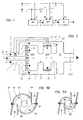
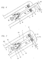
Die Fig. 3 und 4 zeigen zwei Ausführungsbeispiele von Brennkammern, die zum einen für Brennstoff niedrigen Heizwertes, zum andern für Brennstoff hohen Heizwertes konzipiert sind.3 and 4 show two exemplary embodiments of combustion chambers which are designed on the one hand for fuel with a low heating value and on the other hand for fuel with a high heating value.
In Fig. 3 ist mit 50 ein ummanteltes Plenum bezeichnet, welches in der Regel die von einem nicht dargestellten Verdichter geförderte Verbrennungsluft aufnimmt und einer Brennkammer zuführt. Auf die Brennkammer, deren Brennraum VZ durch eine Frontplatte 52 begrenzt ist, ist ein Dom 51 aufgesetzt. In diesem Dom ist ein Brenner 110 so angeordnet, dass der Brenneraustritt 118 zumindest annähernd bündig ist mit der Frontplatte 52. Bei der Brennkammer kann es sich sowohl um eine Ringbrennkammer als auch um eine zylindrische Silobrennkammer handeln. Der dargestellte Fall könnte eine Ringbrennkammer sein, was bedeutet, dass über den Umfang verteilt eine Mehrzahl von Brennern 110 nebeneinander, gleichmässig oder gegeneinander versetzt, auf der kreisringförmigen Frontplatte 52 angeordnet sind.In Fig. 3, 50 is a jacketed plenum, which generally receives the combustion air delivered by a compressor, not shown, and feeds it to a combustion chamber. A
Nach Fig. 3 strömt die Verbrennungsluft aus dem Plenum 50 in das Dominnere. Der Hauptteil PG gelangt durch die Düsenplatte 15 in die Vormischzone VMZ. Der gesamte Brennstoff, in diesem Fall ein Brennstoff mit niedrigem Heizwert, gelangt über die Zufuhrleitung 4 in die Düsenplatte, aus der sie in die Vormischzone eingedüst wird. Dabei wird ein fettes Gemisch erzielt, welches nicht entflammen kann. Diese Vorvermischung wird dann der Endmischzone EMZ zugeleitet. Im vorliegenden Beispiel übernehmen die obengenannte Brenner 110 die Funktion der Endvermischung.3, the combustion air flows out of the
Beim schematisch in Fig. 3 und 5 dargestellten Vormischbrenner 110 handelt es sich um einen sogenannten Doppelkegelbrenner, wie er beispielsweise aus der EP-B1-0 321 809 bekannt ist. Im wesentlichen besteht er aus zwei hohlen, kegelförmigen Teilkörpern 111, 112, die in Strömungsrichtung ineinandergeschachtelt sind. Dabei sind die jeweiligen Mittelachsen 113, 114 der beiden Teilkörper gegeneinander versetzt. Die benachbarten Wandungen der beiden Teilkörper bilden in deren Längserstreckung tangentiale Schlitze 119 für die Vorvermischung, die auf diese Weise in das Brennerinnere gelangt.The
Für die Zufuhr der Sekundärluft SG ist die vom Dom 51 ausgehende Leitung 2 vorgesehen. Im Brenner 110 sind im Bereich der tangentialen Schlitze 119 in den Wandungen der beiden Teilkörper in Längsrichtung verteilte Einströmöffnungen 117 vorgesehen. Die endgültige Gemischbildung mit der Vorvermischung beginnt somit bereits in der Zone der, Eintrittsschlitze 119.The
Am Brenneraustritt 118 stellt sich eine homogene Brennstoffkonzentration über dem beaufschlagten kreisringförmigen Querschnitt ein. Es entsteht am Brenneraustritt eine definierte kalottenförmige Rückströmzone 122, an deren Spitze die Zündung erfolgt. Soweit sind Doppelkegelbrenner aus der eingangs genannten EP-B1-0 321 809 bekannt.At the
Beim Ausführungsbeispiel nach Fig. 4 strömt die Verbrennungsluft aus dem Plenum 50 ebenfalls in das Dominnere. Hier gelangt die gesamte Luftmenge G durch die Düsenplatte 15 in die Vormischzone VMZ. Ein Teil B des Brennstoff, in diesem Fall ein Brennstoff mit hohem Heizwert, gelangt über die Zufuhrleitung 4 in die Düsenplatte, aus der sie in die Vormischzone eingedüst wird. Dabei wird ein mageres Gemisch erzeugt, welches ebenfalls nicht entflammen kann. Diese Vorvermischung wird dann der Endmischzone EMZ zugeleitet, welche Funktion wiederum der obengenannte Brenner 110 übernimmt.In the exemplary embodiment according to FIG. 4, the combustion air also flows from the
Die magere Vorvermischung strömt über die tangentialen Schlitze des Brenners in das Brennerinnere. Die im Bereich der tangentialen Schlitze in den Wandungen der beiden Teilkörper in Längsrichtung verteilten Einströmöffnungen (Fig.5A und B) dienen nunmehr der Eindüsung des Restbrennstoffes RB, welcher über die zentrale, aus dem Dom herausragende Brennstofflanze 5 herangeführt wird. Die Gemischanreicherung der mageren Vorvermischung mit dem Restbrennstoff RB beginnt auch hier bereits in der Zone der Eintrittsschlitze.The lean premixing flows through the tangential slots of the burner into the interior of the burner. The inflow openings (FIGS. 5A and B) distributed in the longitudinal direction in the region of the tangential slots in the walls of the two partial bodies now serve to inject the residual fuel RB, which is brought in via the
- 11
- LuftleitungAir duct
- 22nd
- Zufuhrmittel, LuftleitungSupply means, air line
- 33rd
- Kanalchannel
- 44th
- Zufuhrmittel, BrennstoffleitungSupply means, fuel line
- 55
- Zufuhrmittel, BrennstoffleitungSupply means, fuel line
- 66
- Zufuhrmittel zwischen VMZ und EMZMeans of supply between VMZ and EMZ
- 77
- Überführung, LuftleitungFlyover, air line
- 1010th
- HauptleitungMain line
- 1515
- DüsenplatteNozzle plate
- 1616
- AustrittsdüsenOutlet nozzles
- 1717th
- AustrittsdüsenOutlet nozzles
- 5050
- Plenumplenum
- 5151
- DomCathedral
- 5252
- Frontplatte der BrennkammerFront plate of the combustion chamber
- 5858
- BrennraumCombustion chamber
- 110110
- DoppelkegelbrennerDouble cone burner
- 111111
- TeilkörperPartial body
- 112112
- TeilkörperPartial body
- 113113
- MittelachseCentral axis
- 114114
- MittelachseCentral axis
- 117117
- GaseinströmöffnungGas inflow opening
- 118118
- Brenneraustritt = BrennraumBurner outlet = combustion chamber
- 119119
- tangentialer Spalttangential gap
- 122122
- kalottenförmige Rückströmzonedome-shaped backflow zone
- BB
- Brennstofffuel
- GG
- sauerstoffhaltiges Gasoxygen-containing gas
- VMVM
- VorvermischungPremixing
- VMZVMZ
- VormischzonePremixing zone
- EMEM
- EndgemischFinal mix
- EMZEMZ
- EndmischzoneFinal mixing zone
- VZVZ
- Verbrennungszone (VZ)Combustion zone (VZ)
- RBRB
- restlicher Brennstoffremaining fuel
- PGPG
- PrimärgasPrimary gas
- SGSG
- SekundärgasSecondary gas
- TGTG
- TertiärgasTertiary gas
- V1V1
- AbsperrorganShut-off device
- V2V2
- AbsperrorganShut-off device
- V3V3
- AbsperrorganShut-off device
Claims (12)
dadurch gekennzeichnet, dass
characterized in that
und die Vorrichtung
and the device
Applications Claiming Priority (2)
| Application Number | Priority Date | Filing Date | Title |
|---|---|---|---|
| DE4446842 | 1994-12-27 | ||
| DE4446842A DE4446842B4 (en) | 1994-12-27 | 1994-12-27 | Method and device for feeding a gaseous fuel into a premix burner |
Publications (3)
| Publication Number | Publication Date |
|---|---|
| EP0719983A1 true EP0719983A1 (en) | 1996-07-03 |
| EP0719983B1 EP0719983B1 (en) | 1999-10-27 |
| EP0719983B2 EP0719983B2 (en) | 2002-08-28 |
Family
ID=6537290
Family Applications (1)
| Application Number | Title | Priority Date | Filing Date |
|---|---|---|---|
| EP95810781A Expired - Lifetime EP0719983B2 (en) | 1994-12-27 | 1995-12-11 | Method and device for feeding gaseous fuel to a premix burner |
Country Status (5)
| Country | Link |
|---|---|
| US (1) | US5895211A (en) |
| EP (1) | EP0719983B2 (en) |
| JP (1) | JPH08233220A (en) |
| CN (1) | CN1106532C (en) |
| DE (2) | DE4446842B4 (en) |
Cited By (2)
| Publication number | Priority date | Publication date | Assignee | Title |
|---|---|---|---|---|
| EP0719983B2 (en) † | 1994-12-27 | 2002-08-28 | Alstom | Method and device for feeding gaseous fuel to a premix burner |
| EP1614963A1 (en) * | 2004-07-09 | 2006-01-11 | Siemens Aktiengesellschaft | Premix Combustion System and Method |
Families Citing this family (22)
| Publication number | Priority date | Publication date | Assignee | Title |
|---|---|---|---|---|
| GB9911867D0 (en) * | 1999-05-22 | 1999-07-21 | Rolls Royce Plc | A combustion chamber assembly and a method of operating a combustion chamber assembly |
| DE10056124A1 (en) * | 2000-11-13 | 2002-05-23 | Alstom Switzerland Ltd | Burner system with staged fuel injection and method of operation |
| WO2005124231A2 (en) * | 2004-06-11 | 2005-12-29 | Vast Power Systems, Inc. | Low emissions combustion apparatus and method |
| CN101243287B (en) * | 2004-12-23 | 2013-03-27 | 阿尔斯托姆科技有限公司 | Premix burner with mixing section |
| WO2008070210A2 (en) * | 2006-06-15 | 2008-06-12 | Indiana University Research And Technology Corporation | Pilot fuel injection for a wave rotor engine |
| EP2179222B2 (en) * | 2007-08-07 | 2021-12-01 | Ansaldo Energia IP UK Limited | Burner for a combustion chamber of a turbo group |
| EP2058590B1 (en) * | 2007-11-09 | 2016-03-23 | Alstom Technology Ltd | Method for operating a burner |
| EP2220433B1 (en) * | 2007-11-27 | 2013-09-04 | Alstom Technology Ltd | Method and device for burning hydrogen in a premix burner |
| TWI325401B (en) * | 2007-12-17 | 2010-06-01 | Duen Gang Mou | Vessel structure |
| US8650881B2 (en) * | 2009-06-30 | 2014-02-18 | General Electric Company | Methods and apparatus for combustor fuel circuit for ultra low calorific fuels |
| US8863525B2 (en) | 2011-01-03 | 2014-10-21 | General Electric Company | Combustor with fuel staggering for flame holding mitigation |
| DE102011050802B4 (en) * | 2011-06-01 | 2013-03-21 | Green Gas Germany Gmbh | Method for operating gas engines with a CH4-containing lean gas and mixing device for carrying out the method |
| US9435539B2 (en) | 2013-02-06 | 2016-09-06 | General Electric Company | Variable volume combustor with pre-nozzle fuel injection system |
| US9689572B2 (en) | 2013-02-06 | 2017-06-27 | General Electric Company | Variable volume combustor with a conical liner support |
| US9422867B2 (en) | 2013-02-06 | 2016-08-23 | General Electric Company | Variable volume combustor with center hub fuel staging |
| US9546598B2 (en) | 2013-02-06 | 2017-01-17 | General Electric Company | Variable volume combustor |
| US9562687B2 (en) | 2013-02-06 | 2017-02-07 | General Electric Company | Variable volume combustor with an air bypass system |
| US9587562B2 (en) | 2013-02-06 | 2017-03-07 | General Electric Company | Variable volume combustor with aerodynamic support struts |
| US9441544B2 (en) | 2013-02-06 | 2016-09-13 | General Electric Company | Variable volume combustor with nested fuel manifold system |
| US9447975B2 (en) | 2013-02-06 | 2016-09-20 | General Electric Company | Variable volume combustor with aerodynamic fuel flanges for nozzle mounting |
| CN106500102B (en) * | 2016-11-04 | 2018-11-13 | 中国科学技术大学 | A kind of controlled thermal Atmosphere Combustion device |
| CN107655001A (en) * | 2017-09-25 | 2018-02-02 | 南京律智诚专利技术开发有限公司 | Intelligent natural gas fired incinerators |
Citations (6)
| Publication number | Priority date | Publication date | Assignee | Title |
|---|---|---|---|---|
| EP0187441A2 (en) | 1984-09-10 | 1986-07-16 | Exxon Research And Engineering Company | Low NOx premix burner |
| DE3512948A1 (en) * | 1985-04-11 | 1986-10-16 | Deutsche Forschungs- und Versuchsanstalt für Luft- und Raumfahrt e.V., 5300 Bonn | BLOW-IN ELEMENT FOR A COMBUSTION REACTOR, ESPECIALLY A STEAM GENERATOR |
| DE3222347C2 (en) * | 1981-06-15 | 1988-06-01 | Hitachi, Ltd., Tokio/Tokyo, Jp | |
| GB2217829A (en) * | 1988-04-05 | 1989-11-01 | Nordsea Gas Tach | Combination burner assembly |
| EP0321809B1 (en) | 1987-12-21 | 1991-05-15 | BBC Brown Boveri AG | Process for combustion of liquid fuel in a burner |
| EP0592717A1 (en) * | 1992-10-16 | 1994-04-20 | Asea Brown Boveri Ag | Gas-operated premix burner |
Family Cites Families (23)
| Publication number | Priority date | Publication date | Assignee | Title |
|---|---|---|---|---|
| GB615163A (en) * | 1900-01-01 | |||
| US1466795A (en) * | 1922-03-03 | 1923-09-04 | Robert M Gibson | Fuel mixer |
| JPS5237611B2 (en) * | 1973-03-01 | 1977-09-24 | ||
| IT989199B (en) * | 1973-06-15 | 1975-05-20 | O F R Spa | COMBUSTION HEAD FOR GASEOUS FUEL BURNERS WITH SPACE LOCALLY LOCATED CONCENTRATION GRADIENT STABILIZATION |
| US3915624A (en) † | 1974-01-04 | 1975-10-28 | Morganite Thermal Designs Ltd | Gas burners |
| FR2569825B1 (en) * | 1984-09-04 | 1988-12-09 | Totalgaz Cie Fse | INTEGRATED PRE-MIXTURE BURNER WITH INTEGRATED PILOT FLAME |
| GB2171789B (en) † | 1985-03-01 | 1989-02-08 | Valor Heating Ltd | Gas burners |
| DE3662462D1 (en) * | 1985-07-30 | 1989-04-20 | Bbc Brown Boveri & Cie | Dual combustor |
| JPS63105304A (en) † | 1986-10-21 | 1988-05-10 | Matsushita Electric Ind Co Ltd | Burner |
| US4982570A (en) * | 1986-11-25 | 1991-01-08 | General Electric Company | Premixed pilot nozzle for dry low Nox combustor |
| US4761132A (en) * | 1987-03-04 | 1988-08-02 | Combustion Tec, Inc. | Oxygen enriched combustion |
| FR2619891B1 (en) † | 1987-09-02 | 1991-09-27 | Gaz De France | GAS BURNER HEAD |
| US4910957A (en) * | 1988-07-13 | 1990-03-27 | Prutech Ii | Staged lean premix low nox hot wall gas turbine combustor with improved turndown capability |
| JPH0684817B2 (en) † | 1988-08-08 | 1994-10-26 | 株式会社日立製作所 | Gas turbine combustor and operating method thereof |
| DE68923413T2 (en) * | 1988-09-07 | 1996-04-04 | Hitachi Ltd | Fuel-air premixing device for a gas turbine. |
| DE9000960U1 (en) * | 1989-02-02 | 1990-04-05 | Joh. Vaillant Gmbh U. Co, 5630 Remscheid, De | |
| JPH0579631A (en) † | 1991-09-19 | 1993-03-30 | Hitachi Ltd | Combustion device facility |
| JP2758301B2 (en) † | 1991-11-29 | 1998-05-28 | 株式会社東芝 | Gas turbine combustor |
| DE4309115A1 (en) * | 1993-03-23 | 1994-09-29 | Viessmann Werke Kg | Process for operating an oil vapor burner |
| US5361586A (en) † | 1993-04-15 | 1994-11-08 | Westinghouse Electric Corporation | Gas turbine ultra low NOx combustor |
| DE4330083A1 (en) * | 1993-09-06 | 1995-03-09 | Abb Research Ltd | Method of operating a premix burner |
| DE4330613A1 (en) † | 1993-09-09 | 1995-03-16 | Siemens Ag | Method and device for driving a gas turbine |
| DE4446842B4 (en) † | 1994-12-27 | 2006-08-10 | Alstom | Method and device for feeding a gaseous fuel into a premix burner |
-
1994
- 1994-12-27 DE DE4446842A patent/DE4446842B4/en not_active Expired - Fee Related
-
1995
- 1995-12-04 US US08/566,954 patent/US5895211A/en not_active Expired - Fee Related
- 1995-12-11 EP EP95810781A patent/EP0719983B2/en not_active Expired - Lifetime
- 1995-12-11 DE DE59507138T patent/DE59507138D1/en not_active Expired - Fee Related
- 1995-12-26 JP JP7339296A patent/JPH08233220A/en not_active Ceased
- 1995-12-27 CN CN95120161A patent/CN1106532C/en not_active Expired - Fee Related
Patent Citations (6)
| Publication number | Priority date | Publication date | Assignee | Title |
|---|---|---|---|---|
| DE3222347C2 (en) * | 1981-06-15 | 1988-06-01 | Hitachi, Ltd., Tokio/Tokyo, Jp | |
| EP0187441A2 (en) | 1984-09-10 | 1986-07-16 | Exxon Research And Engineering Company | Low NOx premix burner |
| DE3512948A1 (en) * | 1985-04-11 | 1986-10-16 | Deutsche Forschungs- und Versuchsanstalt für Luft- und Raumfahrt e.V., 5300 Bonn | BLOW-IN ELEMENT FOR A COMBUSTION REACTOR, ESPECIALLY A STEAM GENERATOR |
| EP0321809B1 (en) | 1987-12-21 | 1991-05-15 | BBC Brown Boveri AG | Process for combustion of liquid fuel in a burner |
| GB2217829A (en) * | 1988-04-05 | 1989-11-01 | Nordsea Gas Tach | Combination burner assembly |
| EP0592717A1 (en) * | 1992-10-16 | 1994-04-20 | Asea Brown Boveri Ag | Gas-operated premix burner |
Cited By (2)
| Publication number | Priority date | Publication date | Assignee | Title |
|---|---|---|---|---|
| EP0719983B2 (en) † | 1994-12-27 | 2002-08-28 | Alstom | Method and device for feeding gaseous fuel to a premix burner |
| EP1614963A1 (en) * | 2004-07-09 | 2006-01-11 | Siemens Aktiengesellschaft | Premix Combustion System and Method |
Also Published As
| Publication number | Publication date |
|---|---|
| EP0719983B1 (en) | 1999-10-27 |
| JPH08233220A (en) | 1996-09-10 |
| DE4446842B4 (en) | 2006-08-10 |
| US5895211A (en) | 1999-04-20 |
| CN1106532C (en) | 2003-04-23 |
| EP0719983B2 (en) | 2002-08-28 |
| CN1137108A (en) | 1996-12-04 |
| DE4446842A1 (en) | 1996-07-04 |
| DE59507138D1 (en) | 1999-12-02 |
Similar Documents
| Publication | Publication Date | Title |
|---|---|---|
| EP0719983B1 (en) | Method and device for feeding gaseous fuel to a premix burner | |
| EP2116766B1 (en) | Burner with fuel lance | |
| EP1292795B1 (en) | Method for operating a burner with staged premix gas injection | |
| EP1812756B1 (en) | Burner starting method | |
| EP0571782B1 (en) | Gasturbine combustor and operating method | |
| EP0274630B1 (en) | Arrangement for a burner | |
| EP2225488B1 (en) | Premix burner for a gas turbine | |
| DE4446945B4 (en) | Gas powered premix burner | |
| EP1754002B1 (en) | Staged premix burner with an injector for liquid fuel | |
| EP1436546B1 (en) | Burner for synthesis gas | |
| EP0433790A1 (en) | Burner | |
| EP0713058A1 (en) | Multi-stage combustion chamber | |
| EP1991810A1 (en) | Round burner | |
| EP0801268A2 (en) | Gas turbine combustor | |
| EP1614967A1 (en) | Method and premixed combustion system | |
| EP0276397A1 (en) | Gas turbine combustor | |
| DE3606625A1 (en) | Pilot burner with low NOx emission for furnace installations, in particular of gas turbine installations, and method of operating it | |
| EP1062461B1 (en) | Combustion chamber and method for operating a combustion chamber | |
| DE102005061486A1 (en) | Combustion chamber with burner and associated operating method | |
| EP1105678B1 (en) | Operating method for a hybrid burner | |
| WO2006015968A1 (en) | Burner, gas turbine and operation of a burner | |
| DE10334228A1 (en) | Operating premix burner involves selecting second, third further fuel nozzle opening groups, applying fuel to them independently of each other so second, third groups form premixing, diffusion stages | |
| EP1559955B1 (en) | Burner | |
| DE102020118325A1 (en) | METHOD OF STAGED COMBUSTION OF A FUEL AND FUEL HEAD | |
| DE19542644B4 (en) | premixed |
Legal Events
| Date | Code | Title | Description |
|---|---|---|---|
| PUAI | Public reference made under article 153(3) epc to a published international application that has entered the european phase |
Free format text: ORIGINAL CODE: 0009012 |
|
| AK | Designated contracting states |
Kind code of ref document: A1 Designated state(s): DE FR GB IT NL |
|
| RAP1 | Party data changed (applicant data changed or rights of an application transferred) |
Owner name: ASEA BROWN BOVERI AG |
|
| 17P | Request for examination filed |
Effective date: 19961212 |
|
| 17Q | First examination report despatched |
Effective date: 19980709 |
|
| GRAG | Despatch of communication of intention to grant |
Free format text: ORIGINAL CODE: EPIDOS AGRA |
|
| GRAG | Despatch of communication of intention to grant |
Free format text: ORIGINAL CODE: EPIDOS AGRA |
|
| GRAH | Despatch of communication of intention to grant a patent |
Free format text: ORIGINAL CODE: EPIDOS IGRA |
|
| GRAH | Despatch of communication of intention to grant a patent |
Free format text: ORIGINAL CODE: EPIDOS IGRA |
|
| GRAA | (expected) grant |
Free format text: ORIGINAL CODE: 0009210 |
|
| AK | Designated contracting states |
Kind code of ref document: B1 Designated state(s): DE FR GB IT NL |
|
| REF | Corresponds to: |
Ref document number: 59507138 Country of ref document: DE Date of ref document: 19991202 |
|
| ITF | It: translation for a ep patent filed |
Owner name: DE DOMINICIS & MAYER S.R.L. |
|
| GBT | Gb: translation of ep patent filed (gb section 77(6)(a)/1977) |
Effective date: 20000128 |
|
| ET | Fr: translation filed | ||
| PG25 | Lapsed in a contracting state [announced via postgrant information from national office to epo] |
Ref country code: NL Free format text: LAPSE BECAUSE OF NON-PAYMENT OF DUE FEES Effective date: 20000701 |
|
| PLBI | Opposition filed |
Free format text: ORIGINAL CODE: 0009260 |
|
| PLBF | Reply of patent proprietor to notice(s) of opposition |
Free format text: ORIGINAL CODE: EPIDOS OBSO |
|
| NLV4 | Nl: lapsed or anulled due to non-payment of the annual fee |
Effective date: 20000701 |
|
| 26 | Opposition filed |
Opponent name: SIEMENS AG ZENTRALABTEILUNG TECHNIK ABTEILUNG ZT P Effective date: 20000726 |
|
| PLBF | Reply of patent proprietor to notice(s) of opposition |
Free format text: ORIGINAL CODE: EPIDOS OBSO |
|
| PLAW | Interlocutory decision in opposition |
Free format text: ORIGINAL CODE: EPIDOS IDOP |
|
| REG | Reference to a national code |
Ref country code: GB Ref legal event code: IF02 |
|
| RAP2 | Party data changed (patent owner data changed or rights of a patent transferred) |
Owner name: ALSTOM |
|
| RTI2 | Title (correction) |
Free format text: METHOD AND DEVICE FOR FEEDING GASEOUS FUEL TO A PREMIX BURNER |
|
| RTI2 | Title (correction) |
Free format text: METHOD AND DEVICE FOR FEEDING GASEOUS FUEL TO A PREMIX BURNER |
|
| PLAW | Interlocutory decision in opposition |
Free format text: ORIGINAL CODE: EPIDOS IDOP |
|
| REG | Reference to a national code |
Ref country code: GB Ref legal event code: 732E |
|
| PUAH | Patent maintained in amended form |
Free format text: ORIGINAL CODE: 0009272 |
|
| STAA | Information on the status of an ep patent application or granted ep patent |
Free format text: STATUS: PATENT MAINTAINED AS AMENDED |
|
| REG | Reference to a national code |
Ref country code: FR Ref legal event code: CD Ref country code: FR Ref legal event code: CA |
|
| 27A | Patent maintained in amended form |
Effective date: 20020828 |
|
| AK | Designated contracting states |
Kind code of ref document: B2 Designated state(s): DE FR GB IT NL |
|
| REG | Reference to a national code |
Ref country code: FR Ref legal event code: TP |
|
| GBTA | Gb: translation of amended ep patent filed (gb section 77(6)(b)/1977) | ||
| ET3 | Fr: translation filed ** decision concerning opposition | ||
| PGFP | Annual fee paid to national office [announced via postgrant information from national office to epo] |
Ref country code: FR Payment date: 20031209 Year of fee payment: 9 |
|
| PG25 | Lapsed in a contracting state [announced via postgrant information from national office to epo] |
Ref country code: FR Free format text: LAPSE BECAUSE OF NON-PAYMENT OF DUE FEES Effective date: 20050831 |
|
| REG | Reference to a national code |
Ref country code: FR Ref legal event code: ST |
|
| PG25 | Lapsed in a contracting state [announced via postgrant information from national office to epo] |
Ref country code: IT Free format text: LAPSE BECAUSE OF NON-PAYMENT OF DUE FEES;WARNING: LAPSES OF ITALIAN PATENTS WITH EFFECTIVE DATE BEFORE 2007 MAY HAVE OCCURRED AT ANY TIME BEFORE 2007. THE CORRECT EFFECTIVE DATE MAY BE DIFFERENT FROM THE ONE RECORDED. Effective date: 20051211 |
|
| PGFP | Annual fee paid to national office [announced via postgrant information from national office to epo] |
Ref country code: DE Payment date: 20051212 Year of fee payment: 11 |
|
| PGFP | Annual fee paid to national office [announced via postgrant information from national office to epo] |
Ref country code: GB Payment date: 20051222 Year of fee payment: 11 |
|
| PG25 | Lapsed in a contracting state [announced via postgrant information from national office to epo] |
Ref country code: DE Free format text: LAPSE BECAUSE OF NON-PAYMENT OF DUE FEES Effective date: 20070703 |
|
| GBPC | Gb: european patent ceased through non-payment of renewal fee |
Effective date: 20061211 |
|
| PG25 | Lapsed in a contracting state [announced via postgrant information from national office to epo] |
Ref country code: GB Free format text: LAPSE BECAUSE OF NON-PAYMENT OF DUE FEES Effective date: 20061211 |