EP0718924A2 - Process for an electrical line fixing strain relief - Google Patents
Process for an electrical line fixing strain relief Download PDFInfo
- Publication number
- EP0718924A2 EP0718924A2 EP95117636A EP95117636A EP0718924A2 EP 0718924 A2 EP0718924 A2 EP 0718924A2 EP 95117636 A EP95117636 A EP 95117636A EP 95117636 A EP95117636 A EP 95117636A EP 0718924 A2 EP0718924 A2 EP 0718924A2
- Authority
- EP
- European Patent Office
- Prior art keywords
- housing
- line
- conductors
- mass
- contact elements
- Prior art date
- Legal status (The legal status is an assumption and is not a legal conclusion. Google has not performed a legal analysis and makes no representation as to the accuracy of the status listed.)
- Withdrawn
Links
- 238000000034 method Methods 0.000 title claims description 18
- 239000004020 conductor Substances 0.000 claims description 41
- 239000011810 insulating material Substances 0.000 claims description 11
- 238000002604 ultrasonography Methods 0.000 claims description 5
- 230000009969 flowable effect Effects 0.000 claims description 4
- 239000000853 adhesive Substances 0.000 claims 1
- 230000001070 adhesive effect Effects 0.000 claims 1
- 239000011343 solid material Substances 0.000 claims 1
- 239000007787 solid Substances 0.000 abstract description 7
- 238000009413 insulation Methods 0.000 abstract description 2
- WABPQHHGFIMREM-UHFFFAOYSA-N lead(0) Chemical compound [Pb] WABPQHHGFIMREM-UHFFFAOYSA-N 0.000 abstract 2
- 238000010438 heat treatment Methods 0.000 abstract 1
- 230000037431 insertion Effects 0.000 abstract 1
- 238000003780 insertion Methods 0.000 abstract 1
- 239000000463 material Substances 0.000 description 6
- 239000004831 Hot glue Substances 0.000 description 4
- 239000012774 insulation material Substances 0.000 description 2
- 238000005476 soldering Methods 0.000 description 2
- 230000006978 adaptation Effects 0.000 description 1
- 238000010276 construction Methods 0.000 description 1
- 230000000694 effects Effects 0.000 description 1
- 239000008187 granular material Substances 0.000 description 1
- 230000013011 mating Effects 0.000 description 1
- 230000008719 thickening Effects 0.000 description 1
- 238000003466 welding Methods 0.000 description 1
Images
Classifications
-
- H—ELECTRICITY
- H01—ELECTRIC ELEMENTS
- H01R—ELECTRICALLY-CONDUCTIVE CONNECTIONS; STRUCTURAL ASSOCIATIONS OF A PLURALITY OF MUTUALLY-INSULATED ELECTRICAL CONNECTING ELEMENTS; COUPLING DEVICES; CURRENT COLLECTORS
- H01R4/00—Electrically-conductive connections between two or more conductive members in direct contact, i.e. touching one another; Means for effecting or maintaining such contact; Electrically-conductive connections having two or more spaced connecting locations for conductors and using contact members penetrating insulation
- H01R4/70—Insulation of connections
-
- H—ELECTRICITY
- H01—ELECTRIC ELEMENTS
- H01R—ELECTRICALLY-CONDUCTIVE CONNECTIONS; STRUCTURAL ASSOCIATIONS OF A PLURALITY OF MUTUALLY-INSULATED ELECTRICAL CONNECTING ELEMENTS; COUPLING DEVICES; CURRENT COLLECTORS
- H01R13/00—Details of coupling devices of the kinds covered by groups H01R12/70 or H01R24/00 - H01R33/00
- H01R13/58—Means for relieving strain on wire connection, e.g. cord grip, for avoiding loosening of connections between wires and terminals within a coupling device terminating a cable
- H01R13/582—Means for relieving strain on wire connection, e.g. cord grip, for avoiding loosening of connections between wires and terminals within a coupling device terminating a cable the cable being clamped between assembled parts of the housing
- H01R13/5825—Means for relieving strain on wire connection, e.g. cord grip, for avoiding loosening of connections between wires and terminals within a coupling device terminating a cable the cable being clamped between assembled parts of the housing the means comprising additional parts captured between housing parts and cable
-
- H—ELECTRICITY
- H01—ELECTRIC ELEMENTS
- H01R—ELECTRICALLY-CONDUCTIVE CONNECTIONS; STRUCTURAL ASSOCIATIONS OF A PLURALITY OF MUTUALLY-INSULATED ELECTRICAL CONNECTING ELEMENTS; COUPLING DEVICES; CURRENT COLLECTORS
- H01R13/00—Details of coupling devices of the kinds covered by groups H01R12/70 or H01R24/00 - H01R33/00
- H01R13/58—Means for relieving strain on wire connection, e.g. cord grip, for avoiding loosening of connections between wires and terminals within a coupling device terminating a cable
- H01R13/5845—Means for relieving strain on wire connection, e.g. cord grip, for avoiding loosening of connections between wires and terminals within a coupling device terminating a cable the strain relief being achieved by molding parts around cable and connections
-
- H—ELECTRICITY
- H01—ELECTRIC ELEMENTS
- H01R—ELECTRICALLY-CONDUCTIVE CONNECTIONS; STRUCTURAL ASSOCIATIONS OF A PLURALITY OF MUTUALLY-INSULATED ELECTRICAL CONNECTING ELEMENTS; COUPLING DEVICES; CURRENT COLLECTORS
- H01R43/00—Apparatus or processes specially adapted for manufacturing, assembling, maintaining, or repairing of line connectors or current collectors or for joining electric conductors
- H01R43/20—Apparatus or processes specially adapted for manufacturing, assembling, maintaining, or repairing of line connectors or current collectors or for joining electric conductors for assembling or disassembling contact members with insulating base, case or sleeve
- H01R43/24—Assembling by moulding on contact members
Definitions
- the invention relates to a method for strain-relieved fixing of an electrical line in a housing made of insulating material, with which first electrical contact elements are electrically conductively connected to the conductors of the line and with which the contact elements thereafter together with the end of the line, in which the conductor of Insulating material are enclosed, introduced into the prefabricated, two-part housing and immovably fixed therein (DE-OS 42 21 238).
- contact elements are designed as plug contacts, such as pins or sockets
- the housings can be parts of plug connectors.
- the housing can also surround the connection point between two lines.
- Contact elements are then the conductors of further lines.
- counter contacts are plugged onto the plug contacts accommodated in the housing, which can also be arranged in a housing.
- their conductors are soldered or welded together, for example.
- the contact elements designed as plug pins are pressed against the other part of the housing by projections attached to one part of the housing in such a way that they are not axially movable.
- the line formed as a flat conductor ribbon cable is clamped in a step-like manner and clamped in a joint between the two parts of the housing.
- the invention has for its object to develop the above-described method so that it can be used for arbitrarily constructed lines.
- the end of an electrical line can be fixed in a simple manner in a housing without strain relief without the need for a dimensionally accurate adaptation of the housing and the line.
- only a certain amount of a mass is applied to the end of the line protruding into the housing, which mass sticks to the line or to its insulating material.
- the design of the housing and the line are arbitrary. It can round and flat cables with any number of conductors or cores can be used.
- the solid mass that sticks to the insulation material of the pipe adheres firmly to it. It acts as a thickening of the same.
- connection points between conductors and contact elements are thus effectively protected against tensile loads that could be transmitted via the line. This protection is improved when the mass extends beyond the connection points between conductors and contact elements. The amount of mass is measured relatively precisely. It is then ensured, for example, that plug-in connectors connected to the line are not covered, but remain free to make contact.
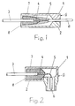
- the connector shown in Fig. 1 has a housing G consisting of two parts 1 and 2 made of plastic.
- the two parts 1 and 2 of the housing G can be connected to one another, for example, by latching elements or by Ultrasonically welded together.
- An electrical line 3 is introduced into the housing G on one side, which has, for example, two wires 4, of which only one can be seen.
- Connector pins 6 are connected in an electrically conductive manner to the conductors 5 of the wires 4. This can be done, for example, by soldering, by welding or by squeezing.
- the connector pins 6 can protrude from the housing G. In any case, they are accessible on the side opposite line 3 for plugging in mating contacts.
- the end of the line 3 is embedded within the housing G in a mass 7 which is firmly glued to the insulating material of the line 3 or the wires 4.
- the mass 7 is, for example, a hot melt adhesive. It also bears against the wall 8 of the housing G, through which the line 3 is inserted into the same. Tensile stresses which are exerted on the line 3 in the axial direction are accordingly absorbed by the mass 7. They cannot affect the connection points between the conductors 5 and the plug pins 6.
- the connector pins 6 themselves are so firmly attached in the housing G that they are also not movable in the axial direction.
- the mass 7, as indicated by dashed lines, can also extend beyond the connection points between the conductors 5 and the plug pins 6. It can also rest against the wall 8 of the horizontally extending walls of parts 1 and 2.
- FIG. 1 While a rectilinear design of the plug connector is shown in FIG. 1, an angled embodiment is shown in FIG.
- the construction of this connector is basically the same as that of the connector according to FIG. 1. The difference is that the connector pins 6 are angled by 90 ° with respect to the line 3. The line 3 is again against the mass 7 Tension loads in housing G secured. The connection points between the conductors 5 and the connector pins 6 are accordingly strain relieved. In this case, a load on the connector pins 6 in the axial direction cannot have a disruptive effect on the connection points with the conductors 5 even if the connector pins 6 are mounted in the housing G with little play in the axial direction.
- the mass 7 can, for example, be introduced into the housing G after it has been closed.
- part 1 of the housing may have an opening through which the mass 7 is poured in a metered amount. It must be ensured that the mass 7 is in any case on the one hand against the wall 8 of the housing G. On the other hand, the mass 7 must adhere to the insulating material of the line 3 or the wires 4 over a sufficiently long length. In the case of a larger quantity, the mass 7 extends beyond the connection points between the conductors 5 and the plug pins 6. The mass 7 also sticks to its base in this area.
- the material of the mass 7 in the solid state can, for example, be attached in the form of granules or strips in the housing G.
- half-shells made of hot-melt adhesive which are in contact with the line after the housing has been closed. The material adheres to the housing G in all cases. After the housing has been closed, it is briefly converted into the flowable state by external heat so that it can spread and stick to the insulating material of the line 3 or the wires 4.
- the supply of the required heat from the outside can expediently be achieved in that the parts 1 and 2 of the housing G are welded to one another by ultrasound.
- the material of mass 7 flows in the required manner and adheres to line 3 or to wires 4.
- the mass 7 can simultaneously serve to additionally connect the two parts 1 and 2 of the housing G to one another if it fills almost the entire clear cross section of the housing G at this end of the housing G.
- the method according to the invention can be used for lines and housings of any design.
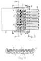
- the method can also advantageously be used with ribbon cables or flat cables, as can be seen from FIGS. 3 and 4. 3 and 4, in contrast to FIGS. 1 and 2, no connector, but the connection point between two electrical lines 9 and 10 is shown.
- line 9 is a flat conductor ribbon cable and line 10 is a round conductor ribbon cable.
- the lines 9 and 10 each have seven conductors in the illustrated embodiment.
- the line 9 has flat conductors 11, while the line 10 has, for example, round stranded conductors 12.
- the number and cross-sectional shape of the lines 9 and 10 are arbitrary.
- the conductors 11 are embedded in a common insulation, while the conductors 12 are individually insulated.
- the insulated conductors 12 are combined to form the above-mentioned round conductor ribbon line as line 10. But it could also be single conductors.
- connection points 13 shown as black dots. The connection points 13 can also be produced by soldering when the conductors 11 and 12 are already inserted in the lower part 2.
- the upper part 1 of the housing G is then snapped onto the lower part 2 or welded to the same by ultrasound.
- the mass 7 can be filled according to the above statements through openings in the upper part 1 in the housing G. It can also be activated by supplying heat (ultrasound) if it was previously attached to at least part of the housing G.
- the mass 7 encloses the ends of the lines 9 and 10 and their conductors 11 and 12 including the connection points 13, as can be seen in FIG. 4.
- flat conductors can also be connected to the conductors 11 of the line 9. It is also possible, for example, to weld the respective conductors to one another if their cross sections permit this.
- the conductors 12 of the further line 10 are also fixed in the housing G, so that no tensile loads can be transmitted from there to the connection points 13 of the conductors 11 and 12 either.
- a suitable material for the mass 7 is, for example, a hot-melt adhesive which is solid at room temperature of approximately 20 ° C. and becomes flowable by the application of heat.
- a hot melt adhesive sticks both to the insulating material of the line 3 or the wires 4 and to the walls of the housing G.
Landscapes
- Connections Effected By Soldering, Adhesion, Or Permanent Deformation (AREA)
- Multi-Conductor Connections (AREA)
Abstract
Description
Die Erfindung betrifft ein Verfahren zur zugentlasteten Festlegung einer elektrischen Leitung in einem aus Isoliermaterial bestehenden Gehäuse, mit welchem zunächst elektrische Kontaktelemente mit den Leitern der Leitung elektrisch leitend verbunden werden und mit welchem die Kontaktelemente danach zusammen mit dem Ende der Leitung, in welchem deren Leiter von Isoliermaterial umschlossen sind, in das vorgefertigte, aus zwei Teilen bestehende Gehäuse eingebracht und unverrückbar in demselben festgelegt werden (DE-OS 42 21 238).The invention relates to a method for strain-relieved fixing of an electrical line in a housing made of insulating material, with which first electrical contact elements are electrically conductively connected to the conductors of the line and with which the contact elements thereafter together with the end of the line, in which the conductor of Insulating material are enclosed, introduced into the prefabricated, two-part housing and immovably fixed therein (DE-OS 42 21 238).
Wenn die Kontaktelemente als Steckkontakte, wie Stifte oder Buchsen, ausgebildet sind, können derartige Gehäuse Teile von Steckverbindern sein. Die Gehäuse können aber auch die Verbindungsstelle zwischen zwei Leitungen umgeben. "Kontaktelemente" sind dann die Leiter von weiterführenden Leitungen. Zur Vervollständigung einer Steckverbindung werden beispielsweise auf die in dem Gehäuse untergebrachten Steckkontakte Gegenkontakte aufgesteckt, die ebenfalls in einem Gehäuse angeordnet sein können. Beim Durchverbinden von zwei Leitungen werden deren Leiter beispielsweise miteinander verlötet oder verschweißt. Beim Aufstecken und beim Abziehen von Gegenkontakten werden auf die Kontakte selbst einerseits und auf die Leitung andererseits in axialer Richtung wirkende Kräfte ausgeübt. Durch solche Kräfte, die auch dann auftreten können, wenn von dem Gehäuse die Verbindungsstelle zweier Leitungen umschlossen wird, können ohne Gegenmaßnahmen die Verbindungsstellen zwischen den Leitern und den Steckkontakten bzw. zwischen den Leitern der beiden Leitungen belastet und im ungünstigsten Fall zerstört werden. Die elektrische Verbindung wäre dann unterbrochen und damit unbrauchbar.If the contact elements are designed as plug contacts, such as pins or sockets, such housings can be parts of plug connectors. The housing can also surround the connection point between two lines. "Contact elements" are then the conductors of further lines. To complete a plug connection, for example, counter contacts are plugged onto the plug contacts accommodated in the housing, which can also be arranged in a housing. When connecting two lines, their conductors are soldered or welded together, for example. When plugging in and removing counter contacts, forces exerted on the contacts themselves on the one hand and on the line on the other in the axial direction. Such forces, which can also occur when the connection point between two lines is enclosed by the housing, can be used without countermeasures Joints between the conductors and the plug contacts or between the conductors of the two lines are loaded and destroyed in the worst case. The electrical connection would then be interrupted and therefore unusable.
Bei dem aus der eingangs erwähnten DE-OS 42 21 238 entnehmbaren Verfahren werden die als Steckerstifte ausgebildeten Kontaktelemente durch an einem Teil des Gehäuses angebrachte Vorsprünge derart gegen den anderen Teil desselben gedrückt, daß sie axial nicht beweglich sind. Zusätzlich wird die als Flachleiter-Bandleitung ausgebildete Leitung stufenförmig gebogen in einer Trennfuge zwischen den beiden Teilen des Gehäuses eingeklemmt. Diese Anordnung mit zugehörigem Verfahren hat sich bewährt. Sie wird mit Vorteil bei Flachleiter-Bandleitungen eingesetzt, die sich relativ problemlos biegen und zwischen den beiden Gehäuseteilen einklemmen lassen.In the method which can be found in the aforementioned DE-OS 42 21 238, the contact elements designed as plug pins are pressed against the other part of the housing by projections attached to one part of the housing in such a way that they are not axially movable. In addition, the line formed as a flat conductor ribbon cable is clamped in a step-like manner and clamped in a joint between the two parts of the housing. This arrangement with the associated method has proven itself. It is used with advantage for flat conductor ribbon cables that bend relatively easily and can be clamped between the two housing parts.
Der Erfindung liegt die Aufgabe zugrunde, das eingangs geschilderte Verfahren so weiterzubilden, daß es für beliebig aufgebaute Leitungen eingesetzt werden kann.The invention has for its object to develop the above-described method so that it can be used for arbitrarily constructed lines.
Diese Aufgabe wird gemäß der Erfindung dadurch gelöst, daß das Ende der Leitung innerhalb des Gehäuses in eine an der Wandung des Gehäuses, durch welche die Leitung hindurchtritt, anliegende, mit dem Isoliermaterial der Leitung verklebende und bei Raumtemperatur feste Masse eingebettet wird.This object is achieved according to the invention in that the end of the line inside the housing is embedded in a mass which is fixed to the wall of the housing and through which the line passes, adheres to the insulating material of the line and is solid at room temperature.
Bei Einsatz dieses Verfahrens kann das Ende einer elektrischen Leitung auf einfache Weise zugentlastet in einem Gehäuse festgelegt werden, ohne daß eine maßgenaue Anpassung von Gehäuse und Leitung erforderlich ist. Es wird dazu lediglich auf das in das Gehäuse hineinragende Ende der Leitung eine bestimmte Menge einer Masse aufgebracht, die mit der Leitung bzw. mit deren Isoliermaterial verklebt. Dabei sind die Gestaltung des Gehäuses und der Leitung beliebig. Es können also runde und flache Leitungen mit einer beliebigen Anzahl von Leitern bzw. Adern eingesetzt werden. Die mit dem Isoliermaterial der Leitung verklebende, feste Masse haftet fest an derselben. Sie wirkt dadurch als Verdickung derselben. Da sie außerdem an der Wandung des Gehäuses anliegt, durch welche die Leitung hindurchtritt, wird jede auf dieselbe einwirkende Zugkraft so wirksam abgefangen, daß die Leitung nicht in axialer Richtung bewegt werden kann. Die Verbindungsstellen zwischen Leitern und Kontaktelementen sind also wirksam gegen Zugbelastungen geschützt, die über die Leitung übertragen werden könnten. Verbessert wird dieser Schutz noch dann, wenn die Masse sich bis über die Verbindungsstellen zwischen Leitern und Kontaktelementen erstreckt. Die Menge der Masse wird jeweils relativ genau bemessen. Es ist dann beispielsweise sichergestellt, daß an die Leitung angeschlossene Steckverbinder nicht mit abgedeckt werden, sondern zur Kontaktgabe frei bleiben.When using this method, the end of an electrical line can be fixed in a simple manner in a housing without strain relief without the need for a dimensionally accurate adaptation of the housing and the line. For this purpose, only a certain amount of a mass is applied to the end of the line protruding into the housing, which mass sticks to the line or to its insulating material. The design of the housing and the line are arbitrary. It can round and flat cables with any number of conductors or cores can be used. The solid mass that sticks to the insulation material of the pipe adheres firmly to it. It acts as a thickening of the same. Since it also bears against the wall of the housing through which the line passes, any tensile force acting on it is so effectively absorbed that the line cannot be moved in the axial direction. The connection points between conductors and contact elements are thus effectively protected against tensile loads that could be transmitted via the line. This protection is improved when the mass extends beyond the connection points between conductors and contact elements. The amount of mass is measured relatively precisely. It is then ensured, for example, that plug-in connectors connected to the line are not covered, but remain free to make contact.
Weitere vorteilhafte Ausgestaltungen der Erfindung gehen aus den Unteransprüchen hervor.Further advantageous embodiments of the invention emerge from the subclaims.
Das Verfahren nach der Erfindung wird anhand der Zeichnungen in Ausführungsbeispielen erläutert.The method according to the invention is explained with reference to the drawings in exemplary embodiments.
Es zeigen:
- Fig. 1 und 2 Schnitte durch zwei unterschiedliche unter Einsatz des Verfahrens nach der Erfindung hergestellte Steckverbinder.
- Fig. 3 eine Draufsicht auf ein offenes, die Verbindungsstelle zweier Leitungen umgebendes Gehäuse.
- Fig. 4 einen Schnitt durch Fig. 3 längs der Linie IV - IV.
- 1 and 2 sections through two different connectors manufactured using the method according to the invention.
- Fig. 3 is a plan view of an open housing surrounding the junction of two lines.
- Fig. 4 shows a section through Fig. 3 along the line IV - IV.
Der in Fig. 1 dargestellte Steckverbinder hat ein aus zwei Teilen 1 und 2 bestehendes Gehäuse G aus Kunststoff. Die beiden Teile 1 und 2 des Gehäuses G können beispielsweise durch einrastende Elemente miteinander verbunden oder durch Ultraschall miteinander verschweißt sein. In das Gehäuse G ist auf einer Seite eine elektrische Leitung 3 eingeführt, die beispielweise zwei Adern 4 aufweist, von denen nur eine zu erkennen ist. An die Leiter 5 der Adern 4 sind Steckerstifte 6 elektrisch leitend angeschlossen. Das kann beispielsweise durch Löten, durch Schweißen oder auch durch Verquetschen geschehen. Die Steckerstifte 6 können aus dem Gehäuse G herausragen. Sie sind auf jeden Fall auf der der Leitung 3 gegenüber liegenden Seite zum Aufstecken von Gegenkontakten zugänglich.The connector shown in Fig. 1 has a housing G consisting of two
Das Ende der Leitung 3 ist innerhalb des Gehäuses G in eine Masse 7 eingebettet, welche fest mit dem Isoliermaterial der Leitung 3 bzw. der Adern 4 verklebt ist. Die Masse 7 ist beispielsweise ein Heißschmelzkleber. Sie liegt außerdem an der Wandung 8 des Gehäuses G an, durch welche die Leitung 3 in dasselbe eingeführt ist. Zugbeanspruchungen, die in axialer Richtung auf die Leitung 3 ausgeübt werden, werden dementsprechend von der Masse 7 abgefangen. Sie können sich nicht auf die Verbindungsstellen zwischen den Leitern 5 und den Steckerstiften 6 auswirken. Die Steckerstifte 6 selbst sind im Gehäuse G so fest angebracht, daß sie ebenfalls in axialer Richtung nicht bewegbar sind. Die Masse 7 kann sich, so wie es gestrichelt angedeutet ist, auch bis über die Verbindungsstellen zwischen den Leitern 5 und den Steckerstiften 6 erstrecken. Sie kann auch außer an der Wandung 8 an den horizontal verlaufenden Wandungen der Teile 1 und 2 anliegen.The end of the
Während in Fig. 1 eine geradlinige Ausführung des Steckerverbinders dargestellt ist, geht aus Fig. 2 eine abgewinkelte Ausführungsform hervor. Der Aufbau dieses Steckverbinders ist prinzipiell der gleiche wie beim Steckverbinder nach Fig. 1. Der Unterschied besteht darin, daß die Steckerstifte 6 gegenüber der Leitung 3 um 90° abgewinkelt sind. Die Leitung 3 ist wieder durch die Masse 7 gegen Zugbelastungen im Gehäuse G gesichert. Die Verbindungsstellen zwischen den Leitern 5 und den Steckerstiften 6 sind dementsprechend zugentlastet. Eine Belastung der Steckerstifte 6 in axialer Richtung kann sich in diesem Fall auf die Verbindungsstellen mit den Leitern 5 auch dann nicht störend auswirken, wenn die Steckerstifte 6 in axialer Richtung mit geringem Spiel im Gehäuse G angebracht sind.While a rectilinear design of the plug connector is shown in FIG. 1, an angled embodiment is shown in FIG. The construction of this connector is basically the same as that of the connector according to FIG. 1. The difference is that the
Die Masse 7 kann beispielsweise nach dem Verschließen des Gehäuses G in dasselbe eingebracht werden. Dazu kann beispielsweise der Teil 1 des Gehäuses eine Öffnung haben, durch welche die Masse 7 in dosierter Menge eingefüllt wird. Es muß dabei sichergestellt sein, daß die Masse 7 sich auf jeden Fall einerseits an die Wandung 8 des Gehäuses G anlegt. Andererseits muß die Masse 7 auf einer ausreichend großen Länge mit dem Isoliermaterial der Leitung 3 bzw. der Adern 4 verkleben. Bei einer größeren Menge erstreckt sich die Masse 7 bis über die Verbindungsstellen zwischen den Leitern 5 und den Steckerstiften 6. Auch in diesem Bereich verklebt die Masse 7 mit ihrer Unterlage.The
Es ist auch möglich, das Material der Masse 7 in festem Zustand bereits vor dem Verschließen des Gehäuses G zumindest an einem der beiden Teile 1 und 2 desselben anzubringen, also im Gehäuse G zu deponieren. Dieses Material kann beispielsweise in Granulat- oder Bandform im Gehäuse G angebracht werden. Es können auch Halbschalen aus einem Heißschmelzkleber eingesetzt werden, die nach dem Verschließen des Gehäuses an der Leitung anliegen. Das Material haftet in allen Fällen am Gehäuse G. Es wird nach Verschließen desselben durch äußere Wärmezufuhr kurzzeitig in den fließfähigen Zustand überführt, so daß es sich ausbreiten und mit dem Isoliermaterial der Leitung 3 bzw. der Adern 4 verkleben kann. Das Zuführen der dazu erforderlichen Wärme von außen kann zweckmäßig dadurch erreicht werden, daß die Teile 1 und 2 des Gehäuses G durch Ultraschall miteinander verschweißt werden.It is also possible to attach the material of the
Bei der dabei entstehenden Wärme fließt das Material der Masse 7 in der erforderlichen Weise und verklebt mit der Leitung 3 bzw. mit den Adern 4.In the heat generated, the material of
Die Masse 7 kann insbesondere in diesem Fall gleichzeitig dazu dienen, die beiden Teile 1 und 2 des Gehäuses G zusätzlich miteinander zu verbinden, wenn sie an diesem Ende des Gehäuses G nahezu den gesamten lichten Querschnitt desselben ausfüllt.In this case in particular, the
Das Verfahren nach der Erfindung kann, wie bereits weiter oben erwähnt, für Leitungen und Gehäuse beliebiger Gestaltung angewendet werden. Neben der in den Fig. 1 und 2 dargestellten Verwendung mit Rundleitungen, kann das Verfahren mit Vorteil auch bei Bandleitungen bzw. Flachleitungen eingesetzt werden, so wie es aus den Fig. 3 und 4 hervorgeht. In den Fig. 3 und 4 ist im Gegensatz zu den Fig. 1 und 2 kein Steckverbinder, sondern die Verbindungsstelle zwischen zwei elektrischen Leitungen 9 und 10 dargestellt. Dabei ist im dargestellten Ausführungsbeispiel die Leitung 9 eine Flachleiter-Bandleitung und die Leitung 10 eine Rundleiter-Bandleitung.As already mentioned above, the method according to the invention can be used for lines and housings of any design. In addition to the use with round cables shown in FIGS. 1 and 2, the method can also advantageously be used with ribbon cables or flat cables, as can be seen from FIGS. 3 and 4. 3 and 4, in contrast to FIGS. 1 and 2, no connector, but the connection point between two
Die Leitungen 9 und 10 haben im dargestellten Ausführungsbeispiel jeweils sieben Leiter. Die Leitung 9 weist flache Leiter 11 auf, während die Leitung 10 beispielsweise runde Litzenleiter 12 hat. Anzahl und Querschnittsform der Leitungen 9 und 10 sind aber beliebig. Die Leiter 11 sind in eine gemeinsame Isolierung eingebettet, während die Leiter 12 einzeln isoliert sind. Die isolierten Leiter 12 sind zu der oben erwähnten Rundleiter-Bandleitung als Leitung 10 zusammengefaßt. Es könnten aber auch Einzelleiter sein.The
Die jeweiligen Leiter 11 und 12 der Leitungen 9 und 10 werden zunächst beispielsweise miteinander verlötet, was durch die als schwarze Punkte eingezeichneten Verbindungsstellen 13 angedeutet sein soll. Danach werden beide Leitungsenden mit den Verbindungsstellen 13 in das Unterteil 2 des Gehäuses G eingelegt. Die Verbindungsstellen 13 können aber auch dann durch Löten hergestellt werden, wenn die Leiter 11 und 12 bereits in das Unterteil 2 eingelegt sind. Anschließend wird das Oberteil 1 des Gehäuses G auf das Unterteil 2 aufgeschnappt oder durch Ultraschall mit demselben verschweißt. Die Masse 7 kann entsprechend obigen Ausführungen durch Öffnungen im Oberteil 1 in das Gehäuse G eingefüllt werden. Sie kann auch durch Wärmezufuhr (Ultraschall) aktiviert werden, wenn sie bereits vorher mindestens an einem Teil des Gehäuses G angebracht war. Die Masse 7 umschließt hier die Enden der Leitungen 9 und 10 und deren Leiter 11 und 12 einschließlich der Verbindungsstellen 13, so wie es aus Fig. 4 hervorgeht.The
An die Leiter 11 der Leitung 9 können in Abweichung von der Darstellung in den Fig. 3 und 4 ebenfalls Flachleiter angeschlossen werden. Es ist auch möglich, die jeweiligen Leiter beispielweise miteinander zu verschweißen, wenn ihre Querschnitte das zulassen. Die Leiter 12 der weiterführenden Leitung 10 sind im Gehäuse G ebenfalls zugentlastet festgelegt, so daß von dort aus ebenfalls keine Zugbelastungen auf die Verbindungsstellen 13 der Leiter 11 und 12 übertragen werden können.In deviation from the illustration in FIGS. 3 and 4, flat conductors can also be connected to the
Als Material für die Masse 7 eignet sich - wie schon weiter oben erwähnt - beispielweise ein Heißschmelzkleber, der bei Raumtemperatur von etwa 20 °C fest ist und durch Wärmezufuhr fließfähig wird. Ein solcher Heißschmelzkleber verklebt sowohl mit dem Isoliermaterial der Leitung 3 bzw. der Adern 4 als auch mit den Wandungen des Gehäuses G. Es sind jedoch auch alle anderen geeigneten Materialien einsetzbar, die bei Wärmezufuhr fließfähig werden und sich auf jeden Fall durch Kleben fest mit dem Isoliermaterial der Leitung 3 bzw. der Adern 4 und mit dem Gehäuse G verbinden.As already mentioned above, a suitable material for the
Claims (8)
Applications Claiming Priority (2)
| Application Number | Priority Date | Filing Date | Title |
|---|---|---|---|
| DE4446768 | 1994-12-24 | ||
| DE4446768 | 1994-12-24 |
Publications (2)
| Publication Number | Publication Date |
|---|---|
| EP0718924A2 true EP0718924A2 (en) | 1996-06-26 |
| EP0718924A3 EP0718924A3 (en) | 1997-08-13 |
Family
ID=6537243
Family Applications (1)
| Application Number | Title | Priority Date | Filing Date |
|---|---|---|---|
| EP95117636A Withdrawn EP0718924A3 (en) | 1994-12-24 | 1995-11-09 | Process for an electrical line fixing strain relief |
Country Status (2)
| Country | Link |
|---|---|
| EP (1) | EP0718924A3 (en) |
| DE (1) | DE19510341A1 (en) |
Cited By (3)
| Publication number | Priority date | Publication date | Assignee | Title |
|---|---|---|---|---|
| EP0836253A3 (en) * | 1996-10-11 | 1999-03-31 | Alcatel | Arrangement for protecting an electric line |
| CN109478751A (en) * | 2016-07-12 | 2019-03-15 | 株式会社自动网络技术研究所 | Manufacturing method of electrical connection assembly |
| US11894649B2 (en) | 2020-10-30 | 2024-02-06 | Amphenol Corporation | Electrical connector and method of making the same |
Families Citing this family (2)
| Publication number | Priority date | Publication date | Assignee | Title |
|---|---|---|---|---|
| DE10053280A1 (en) * | 2000-10-27 | 2002-05-16 | Hirschmann Austria Gmbh Rankwe | Connector for ribbon cables has ultrasonically welded strip to protect against pulling forces |
| DE102004034804A1 (en) | 2004-07-19 | 2006-03-16 | Saint-Gobain Sekurit Deutschland Gmbh & Co. Kg | Electrical line connection with cross-sectional transition and composite pane |
Citations (1)
| Publication number | Priority date | Publication date | Assignee | Title |
|---|---|---|---|---|
| DE4221238A1 (en) | 1991-10-07 | 1993-04-08 | Kabelmetal Electro Gmbh | Flat ribbon cable cassette for use in steering wheel control connections - has ribbon wound in spiral form in sealed housing with connecting pin assemblies at each end |
Family Cites Families (7)
| Publication number | Priority date | Publication date | Assignee | Title |
|---|---|---|---|---|
| US4083902A (en) * | 1977-01-10 | 1978-04-11 | Raychem Corporation | Method of sealing a connector |
| US4643924A (en) * | 1985-03-25 | 1987-02-17 | Raychem Corporation | Protective article comprising an elastic gel |
| EP0272039A2 (en) * | 1986-12-19 | 1988-06-22 | AT&T Corp. | Apparatus having electrical connections embedded in a potting compound |
| WO1990007808A1 (en) * | 1988-12-24 | 1990-07-12 | Schunk Ultraschalltechnik Gmbh | Process and device for surrounding a junction point between electrically conductive elements |
| FR2663791A1 (en) * | 1990-06-22 | 1991-12-27 | Tecnoffra | Sealing device for electrical connection cases (boxes) |
| DE4116748C1 (en) * | 1991-05-23 | 1992-10-01 | Leopold Kostal Gmbh & Co Kg, 5880 Luedenscheid, De | Multi-lead electrical coupling component - has sealing material channel and trough extending from plug region to achieve watertightness |
| US5110306A (en) * | 1991-07-24 | 1992-05-05 | W. L. Gore & Associates, Inc. | Compact connector assembly and termination guide therefor |
-
1995
- 1995-03-22 DE DE19510341A patent/DE19510341A1/en not_active Withdrawn
- 1995-11-09 EP EP95117636A patent/EP0718924A3/en not_active Withdrawn
Patent Citations (1)
| Publication number | Priority date | Publication date | Assignee | Title |
|---|---|---|---|---|
| DE4221238A1 (en) | 1991-10-07 | 1993-04-08 | Kabelmetal Electro Gmbh | Flat ribbon cable cassette for use in steering wheel control connections - has ribbon wound in spiral form in sealed housing with connecting pin assemblies at each end |
Cited By (4)
| Publication number | Priority date | Publication date | Assignee | Title |
|---|---|---|---|---|
| EP0836253A3 (en) * | 1996-10-11 | 1999-03-31 | Alcatel | Arrangement for protecting an electric line |
| CN109478751A (en) * | 2016-07-12 | 2019-03-15 | 株式会社自动网络技术研究所 | Manufacturing method of electrical connection assembly |
| CN109478751B (en) * | 2016-07-12 | 2020-12-11 | 株式会社自动网络技术研究所 | Manufacturing method of electrical connection assembly |
| US11894649B2 (en) | 2020-10-30 | 2024-02-06 | Amphenol Corporation | Electrical connector and method of making the same |
Also Published As
| Publication number | Publication date |
|---|---|
| DE19510341A1 (en) | 1996-06-27 |
| EP0718924A3 (en) | 1997-08-13 |
Similar Documents
| Publication | Publication Date | Title |
|---|---|---|
| DE19800099C2 (en) | Method of making a line connector | |
| DE69205916T2 (en) | Structure for laser welding of electrical connections. | |
| DE1765654A1 (en) | Connection device for printed circuits | |
| EP0542005A1 (en) | Procedure for fabrication an electrical connection between two electrical conductors | |
| DE19934967C2 (en) | Waterproof connector | |
| DE4439645C1 (en) | Power connector for a heated car glass | |
| DE2735838C2 (en) | Electrical terminal and electrical cable connector | |
| DE69712028T2 (en) | Structure and method of connecting an electrical wire to an end clamp | |
| EP0496972A1 (en) | Plug connector especially for removable connection of electric conductors | |
| DE19922139B4 (en) | A method of mounting a flat cable to a connector, a connector for a flat cable, and a component for exciting ultrasonic vibrations for use in this method | |
| EP0090317A2 (en) | Connecting device for electrical conductors having the form of a wire or a strand | |
| DE2355873C2 (en) | Cable connector | |
| DE19823900C2 (en) | Connection element, connection structure between a connection element and a covered wire and method for connecting a connection element with a covered wire | |
| EP3782235A1 (en) | Direct plug connector | |
| EP0718924A2 (en) | Process for an electrical line fixing strain relief | |
| DE4222685C2 (en) | Plug contact element | |
| EP0945929B1 (en) | Connector for shielded cable | |
| EP1831965A1 (en) | Sealing element for flexible flat cables (ffc), fpc and other flat lines with or without round conductors | |
| DE19949386C2 (en) | Device connection box with cutting technology | |
| EP0272470A1 (en) | Electrical plug and method of producing the same | |
| DE102015121832B4 (en) | Plug connector for direct electrical contact and plug connection | |
| EP1083627B1 (en) | Electrical connector assembly | |
| DE19525801C2 (en) | Device for the electrically conductive connection of two electrical lines | |
| DE2165442A1 (en) | PLUG CONNECTION FOR ELECTRICAL CABLES AND PROCESS FOR PRODUCING THE PLUG CONNECTION. | |
| DE3719210C2 (en) | Method for producing a coupling part of an electrical connector |
Legal Events
| Date | Code | Title | Description |
|---|---|---|---|
| PUAI | Public reference made under article 153(3) epc to a published international application that has entered the european phase |
Free format text: ORIGINAL CODE: 0009012 |
|
| AK | Designated contracting states |
Kind code of ref document: A2 Designated state(s): DE FR IT SE |
|
| PUAL | Search report despatched |
Free format text: ORIGINAL CODE: 0009013 |
|
| AK | Designated contracting states |
Kind code of ref document: A3 Designated state(s): DE FR IT SE |
|
| 17P | Request for examination filed |
Effective date: 19970711 |
|
| 17Q | First examination report despatched |
Effective date: 19990212 |
|
| GRAG | Despatch of communication of intention to grant |
Free format text: ORIGINAL CODE: EPIDOS AGRA |
|
| GRAG | Despatch of communication of intention to grant |
Free format text: ORIGINAL CODE: EPIDOS AGRA |
|
| GRAH | Despatch of communication of intention to grant a patent |
Free format text: ORIGINAL CODE: EPIDOS IGRA |
|
| STAA | Information on the status of an ep patent application or granted ep patent |
Free format text: STATUS: THE APPLICATION IS DEEMED TO BE WITHDRAWN |
|
| 18D | Application deemed to be withdrawn |
Effective date: 20000328 |