EP0718800B1 - Frankiermaschine mit einem Reservespeicher - Google Patents
Frankiermaschine mit einem Reservespeicher Download PDFInfo
- Publication number
- EP0718800B1 EP0718800B1 EP19940120219 EP94120219A EP0718800B1 EP 0718800 B1 EP0718800 B1 EP 0718800B1 EP 19940120219 EP19940120219 EP 19940120219 EP 94120219 A EP94120219 A EP 94120219A EP 0718800 B1 EP0718800 B1 EP 0718800B1
- Authority
- EP
- European Patent Office
- Prior art keywords
- memory
- franking machine
- reserve
- data
- voltage
- Prior art date
- Legal status (The legal status is an assumption and is not a legal conclusion. Google has not performed a legal analysis and makes no representation as to the accuracy of the status listed.)
- Expired - Lifetime
Links
Images

Classifications
-
- G—PHYSICS
- G07—CHECKING-DEVICES
- G07B—TICKET-ISSUING APPARATUS; FARE-REGISTERING APPARATUS; FRANKING APPARATUS
- G07B17/00—Franking apparatus
- G07B17/00185—Details internally of apparatus in a franking system, e.g. franking machine at customer or apparatus at post office
- G07B17/00362—Calculation or computing within apparatus, e.g. calculation of postage value
-
- G—PHYSICS
- G07—CHECKING-DEVICES
- G07B—TICKET-ISSUING APPARATUS; FARE-REGISTERING APPARATUS; FRANKING APPARATUS
- G07B17/00—Franking apparatus
- G07B17/00185—Details internally of apparatus in a franking system, e.g. franking machine at customer or apparatus at post office
- G07B17/00314—Communication within apparatus, personal computer [PC] system, or server, e.g. between printhead and central unit in a franking machine
-
- G—PHYSICS
- G07—CHECKING-DEVICES
- G07B—TICKET-ISSUING APPARATUS; FARE-REGISTERING APPARATUS; FRANKING APPARATUS
- G07B17/00—Franking apparatus
- G07B17/00185—Details internally of apparatus in a franking system, e.g. franking machine at customer or apparatus at post office
- G07B17/00314—Communication within apparatus, personal computer [PC] system, or server, e.g. between printhead and central unit in a franking machine
- G07B2017/00346—Power handling, e.g. power-down routine
-
- G—PHYSICS
- G07—CHECKING-DEVICES
- G07B—TICKET-ISSUING APPARATUS; FARE-REGISTERING APPARATUS; FRANKING APPARATUS
- G07B17/00—Franking apparatus
- G07B17/00185—Details internally of apparatus in a franking system, e.g. franking machine at customer or apparatus at post office
- G07B17/00362—Calculation or computing within apparatus, e.g. calculation of postage value
- G07B2017/00395—Memory organization
-
- G—PHYSICS
- G07—CHECKING-DEVICES
- G07B—TICKET-ISSUING APPARATUS; FARE-REGISTERING APPARATUS; FRANKING APPARATUS
- G07B17/00—Franking apparatus
- G07B17/00185—Details internally of apparatus in a franking system, e.g. franking machine at customer or apparatus at post office
- G07B17/00362—Calculation or computing within apparatus, e.g. calculation of postage value
- G07B2017/00395—Memory organization
- G07B2017/00411—Redundant storage, e.g. back-up of registers
Definitions
- the invention relates to a franking machine with an electronic Controller accessing a first memory in which security-relevant data is stored and from which these data are available again, and with at least one non-volatile reserve memory, in the event of a power failure the data of the first memory are stored and after Power recovery returns the data of the reserve memory are readable.
- a franking machine with a Voltage monitoring circuit known that the sinking and the return of the operating voltage is detected.
- the franking machine has a non-volatile reserve memory, in the data from the working memory when the operating voltage drops can be saved by copying. If the operating voltage rises again, the im will not volatile memory stored data back into memory transferred to the franking machine.
- a franking machine is from US-A-4,564,922 known with two reserve memories.
- One of these stores is one non-volatile read-only memory while the other Memory works as a so-called shadow work memory, that has two memory sections.
- a first storage section serves as a volatile memory
- a second Memory section provided as a non-volatile memory is.
- data is stored in the shadow RAM from the volatile memory section to the non volatile memory section transferred by a copy operation. After the voltage returns, data stored in the non-volatile memory section of the shadow memory were saved to a computer unit and with non-volatile data from the read-only memory Matched.
- a franking machine is known from EP-A-0 572 019 has at least two non-volatile memories.
- the Operating voltage will be safety relevant data in both non-volatile memory inscribed.
- the data from the two memories is replaced by a Transfer the copying process to the computer of the franking machine and checked for identity there.
- the known devices and methods copy each an entire data set on voltage drop and on voltage recovery. This means that a large number of data must be transferred between the memories. At this Transmission read and write errors can occur which affect the reliability of the franking machine. Multiple storage in non-volatile memories and the subsequent comparison of the data records with each other increases the data security for franking machines, however when interference signals occur, for example caused by voltage induction or by voltage peaks be the data from different stores get to the computer when transferring data, in the same way affected, causing a systematic data error can come up with an identity of different records is faked.
- a franking machine is known from EP-A-0 550 994, which has two memories contains which by a controller as static non-volatile memory or can be operated as dynamic volatile memories.
- the two stores serve both for storing security-relevant data and as working memory. Depending on the level of the supply voltage, the two memories are in switched to static or dynamic operation.
- the reserve memory is not as static volatile memory operable; another time than dynamic volatile memory. In static operation, they are stored in the reserve memory stored data quasi frozen, whereby in this state of the reserve memory no further power supply needed more. When the voltage returns, the Reserve memory cells set to dynamic state, in the continuous refresh cycles for the memory content required are.
- a ferroelectric memory is provided.
- Ferroelectric memory cells Material as a storage medium.
- the data are called states stored by storage capacitors. These storage capacitors form the memory cells of the ferroelectric Memory.
- the data In the static mode, the data is through defines the polarization state of the memory cells; in the dynamic operating mode, the data is considered the state of charge of the Memory cells mapped.
- the use of a ferroelectric Memory in connection with common other technologies for memory and non-volatile memory, for example battery-backed memory has the advantage that the simultaneous occurrence of write and read errors interfering signals due to different storage technologies is avoided.
- a further development of the invention is characterized in that a Area of the reserve memory for storing a control program is provided.
- the reserve memory serves in this Case as read-only memory, which in this application at least partially replaced the usual ROM module. Through this training, the hardware effort for the Franking machine reduced. It is also possible to create an area of the reserve memory as working memory for the control to provide.
- the controller 10 is the in a block diagram Postage meter shown. It contains a microprocessor 12 with a data bus 16 and an address bus 14 with a decoding unit 18, a working memory 20, a EPROM designed program memory 22, one as EEPROM trained memory for fixed data, a clock module 16 with a battery-backed first non-volatile memory 26, also as a battery-backed second non-volatile memory 28, as a ferroelectric reserve memory 30 trained third non-volatile memories, a further decoding unit 32, an interface module 34 for external units and an interface module 36 for a display and for input means electrical connected is.
- the two decoding units 18 and 32 are in summarized a customer-specific ASIC module 40.
- the Decoding unit 32 has lines 46, 46a, 46b which are connected to the Chip select inputs CS of the reserve memory 30, the memory 28 and the memory 26 are connected. Over these lines 46, 46a, 46b the memories 30, 28, 26 are selected, to read and write data.
- An output portl of the microprocessor 12 is via a control line 48 to the input D / NV of the reserve memory 30 connected. Depending on the signal on the control line 48, the reserve memory 30 in the operating mode "dynamic memory” or "static memory” switched.
- first, second and third non-volatile memories 26, 28, 30 security-relevant data of the franking machine, for example the still available postage amount and the Postage amount already issued, each saved.
- the three non-volatile memories 26, 28, 30 operate according to different ones Technologies, so that high storage security also possible under unfavorable operating conditions is.
- the microprocessor 12 compares at certain time intervals those stored in the three memories 26, 28, 30 security-relevant data among each other. If the An error signal is generated from data from each other or it is causes an error correction, as for example in European patent application EP-A-0 572 019 is.
- the microprocessor 12 is connected to a voltage monitoring module 42, which monitors the operating voltage U B on the line 44.
- the ferroelectric reserve memory 30 is operated with the same operating voltage U B as the other components of the control system 10.
- the operation of the franking machine for franking mail using the components shown in FIG. 1 is known per se to the person skilled in the art and must be here not explained in more detail.
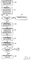
- FIG. 2 shows in a flowchart the function of the reserve memory 30 when a drop in the supply voltage occurs and when the voltage returns.
- the voltage monitoring module 42 reports to the microprocessor 12 that the operating voltage U B has been reached , and in the subsequent step 52 the microprocessor 12 and the structural units connected to it are initialized, including the safety-relevant ones Data in memories 26 and 28 are compared for agreement. If it is determined in step 54 that the security-relevant data do not match, a branch is made to a further program in step 56, in which the error is corrected if necessary.
- the method described in EP-A-0 572 019 can be used here.
- interrupts Events to which the microprocessor 12 responds and control functions triggers
- the processing of interrupts interrupted in order to keep the Change the operating mode of the reserve memory 30 to be able to.
- the reserve memory 30 is activated via the chip select line 46 by the decoding unit 32, and the microprocessor 12 sends a signal via the control line 48 to the input D / NV of the memory 30 to put it into the dynamic operating state to switch.
- the data 30 stored in the memory are continuously renewed.
- the renewal energy is supplied by the supply voltage U B.
- So-called dummy read cycles are subsequently stored in the memory carried out. These cycles are necessary for data storage, i.e. the polarization or charging of the Memory cells depending on the control signal 48 present to change.
- step 64 the lock for the interrupt handling canceled.
- the microprocessor samples the signal of the voltage monitoring module 42. If not Power failure in step 66 becomes normal Postage meter operation (step 68) branches, and the usual Control functions are carried out.
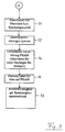
- step 66 branches to program part A, the sequence of which is shown in FIG. 3.
- step 70 the interrupt processing by the microprocessor 12 is blocked in the subsequent step 72.
- the memory 30 is selected via the decoding module 32 and the line 46, and the microprocessor 12 outputs the signal for activating the non-volatile mode of operation of the memory 30 via the control line 48, so that this memory 30 switches to its static mode.
- the dummy read cycles already mentioned are carried out in the subsequent step 76.
- the data in the memory 30 are stored statically. In this state, the memory 30 does not require a voltage supply. It is therefore possible to supply the memory 30 solely from the supply voltage U B , from which the franking machine, with the exception of the battery-buffered memories 26, 28, also draw its electrical energy.
Landscapes
- Physics & Mathematics (AREA)
- Engineering & Computer Science (AREA)
- General Physics & Mathematics (AREA)
- Mathematical Physics (AREA)
- Theoretical Computer Science (AREA)
- Computer Hardware Design (AREA)
- General Engineering & Computer Science (AREA)
- Techniques For Improving Reliability Of Storages (AREA)
- Devices For Checking Fares Or Tickets At Control Points (AREA)
Description
- Figur 1
- die Steuerung einer Frankiermaschine in einer Blockdarstellung, sowie
- Figuren 2 und 3
- die Ablaufschritte beim Einschalten des dynamischen Betriebs bzw. des statischen Betriebs des Reservespeichers.
Claims (7)
- Frankiermaschine mit einer elektronischen Steuerung (10), die auf einen ersten nicht flüchtigen Speicher (26, 28) zugreift, in welchem sicherheitsrelevante Daten gespeichert und aus dem diese Daten wieder abrufbar sind,mit mindestens einem Reservespeicher (30),wobei bei Spannungsausfall die Daten des ersten Speichers (26, 28) im Reservespeicher (30) gespeichert sind und nach Spannungswiederkehr diese Daten aus dem Reservespeicher (30) wieder auslesbar sind,der Reservespeicher als ferroelektrischer Speicher (30) ausgebildet ist, der wahlweise als statischer nicht flüchtiger Speicher oder als dynamischer flüchtiger Speicher betreibbar ist,der Reservespeicher (30) und die Frankiermaschine aus einer gemeinsamen Versorgungsspannung (UB) gespeist werden,und wobei die Steuerung (10) bei Abfall der Versorgungsspannung (UB) auf einen vorgegebenen Wert den Reservespeicher (30) auf den statischen Betrieb und bei Spannungswiederkehr auf den dynamischen Betrieb einstellt, wobei zum Erkennen des Abfalls der Versorgungsspannung (UB) ein Spannungsüberwachungsbaustein (42) vorgesehen ist, der die Versorgungsspannung (UB) mit einem vorgegebenen Vergleichswert vergleicht und bei Unterschreiten des Vergleichswertes ein Signal für die Steuerung (10) erzeugt, die den Reservespeicher (30) durch Abgabe eines Steuersignals in den statischen Betrieb schaltet, dadurch gekennzeichnet, daßder erste Speicher (26, 28) und der Reservespeicher (30) nach unterschied-lichen Technologien arbeiten,daß das Signal ein Interruptsignal ist,daß der Spannungsüberwachungsbaustein (42) bei Spannungswiederkehr ein weiteres Interruptsignal für die Steuerung (10) erzeugt, die den Reservespeicher (30) durch ein Steuersignal in den dynamischen Betrieb schaltet,und daß vor dem Einschalten des statischen Betriebs und des dynamischen Betriebs für den Reservespeicher (30) die Bearbeitung weiterer Interrupts gesperrt ist.
- Frankiermaschine nach Anspruch 1, dadurch gekennzeichnet, daß ein Bereich des Reservespeichers (30) für die Speicherung eines Steuerprogramms vorgesehen ist.
- Frankiermaschine nach einem der vorhergehenden Ansprüche, dadurch gekennzeichnet, daß ein weiterer Bereich des Reservespeichers (30) als Arbeitsspeicher für die Steuerung (10) vorgesehen ist.
- Frankiermaschine nach einem der vorhergehenden Ansprüche, dadurch gekennzeichnet, daß vorbestimmte Bereiche des Reservespeichers (30) schreibgeschützt sind.
- Frankiermaschine nach Anspruch 4, dadurch gekennzeichnet, daß der dem Steuerprogramm zugeordnete Speicherbereich schreibgeschützt ist.
- Frankiermaschine nach einem der vorhergehenden Ansprüche, dadurch gekennzeichnet, daß der erste Speicher (26 oder 28) eine Speichertechnologie hat, bei der er durch eine Batterie oder einen Akkumulator spannungsgepuffert ist.
- Frankiermaschine nach einem der vorhergehenden Ansprüche, dadurch gekennzeichnet, daß als sicherheitsrelevante Daten Portodaten der Frankiermaschine, vorzugsweise der noch verfügbare Portobetrag und der bereits ausgegebene Portobetrag, im Reservespeicher gespeichert sind.
Priority Applications (2)
| Application Number | Priority Date | Filing Date | Title |
|---|---|---|---|
| EP19940120219 EP0718800B1 (de) | 1994-12-20 | 1994-12-20 | Frankiermaschine mit einem Reservespeicher |
| DE59408216T DE59408216D1 (de) | 1994-12-20 | 1994-12-20 | Frankiermaschine mit einem Reservespeicher |
Applications Claiming Priority (1)
| Application Number | Priority Date | Filing Date | Title |
|---|---|---|---|
| EP19940120219 EP0718800B1 (de) | 1994-12-20 | 1994-12-20 | Frankiermaschine mit einem Reservespeicher |
Publications (2)
| Publication Number | Publication Date |
|---|---|
| EP0718800A1 EP0718800A1 (de) | 1996-06-26 |
| EP0718800B1 true EP0718800B1 (de) | 1999-05-06 |
Family
ID=8216548
Family Applications (1)
| Application Number | Title | Priority Date | Filing Date |
|---|---|---|---|
| EP19940120219 Expired - Lifetime EP0718800B1 (de) | 1994-12-20 | 1994-12-20 | Frankiermaschine mit einem Reservespeicher |
Country Status (2)
| Country | Link |
|---|---|
| EP (1) | EP0718800B1 (de) |
| DE (1) | DE59408216D1 (de) |
Families Citing this family (1)
| Publication number | Priority date | Publication date | Assignee | Title |
|---|---|---|---|---|
| US7152049B2 (en) | 2001-10-05 | 2006-12-19 | Pitney Bowes Inc. | Method and system for dispensing virtual stamps |
Family Cites Families (4)
| Publication number | Priority date | Publication date | Assignee | Title |
|---|---|---|---|---|
| US4564922A (en) * | 1983-10-14 | 1986-01-14 | Pitney Bowes Inc. | Postage meter with power-failure resistant memory |
| US4706215A (en) * | 1984-08-22 | 1987-11-10 | Pitney Bowes Inc. | Data protection system for electronic postage meters having multiple non-volatile multiple memories |
| US5187798A (en) * | 1989-03-06 | 1993-02-16 | Pitney Bowes Inc. | Electronic postage meter having separate funds charge registers and recredits funds register in predetermined amount when funds fall to predetermined level |
| GB9126998D0 (en) * | 1991-12-19 | 1992-02-19 | Alcatel Business Machines Limi | Franking machine |
-
1994
- 1994-12-20 EP EP19940120219 patent/EP0718800B1/de not_active Expired - Lifetime
- 1994-12-20 DE DE59408216T patent/DE59408216D1/de not_active Expired - Fee Related
Also Published As
| Publication number | Publication date |
|---|---|
| EP0718800A1 (de) | 1996-06-26 |
| DE59408216D1 (de) | 1999-06-10 |
Similar Documents
| Publication | Publication Date | Title |
|---|---|---|
| DE69323225T2 (de) | Datenbehandlung in einem System mit Prozessor zur Steuerung des Zugangs zu einer Mehrzahl von Datenspeicherplatten | |
| DE2400161C2 (de) | ||
| DE69613266T2 (de) | Leseverfahren eines ferroelektrischen Speichers unter Verwendung von unterschiedlichen Lese- und Schreibespannungen | |
| DE69125078T2 (de) | Halbleiter-Speichersystem | |
| EP0163096A1 (de) | Einrichtung zur Rettung eines Rechnerzustandes | |
| EP0195885B1 (de) | Verfahren und Anordnung zum nichtflüchtigen Speichern des Zählerstandes einer elektronischen Zählschaltung | |
| DE69126057T2 (de) | Ein Informationsverarbeitungsgerät mit einer Fehlerprüf- und Korrekturschaltung | |
| DE2523414B2 (de) | Hierarchische Speicheranordnung mit mehr als zwei Speicherstufen | |
| DE2741886A1 (de) | Datenuebertragungseinrichtung | |
| DE2225841C3 (de) | Verfahren und Anordnung zur systematischen Fehlerprüfung eines monolithischen Halbleiterspeichers | |
| DE2715751B2 (de) | Speicheranordnung mit defekten Modulen | |
| DE2210325A1 (de) | Datenverarbeitungssystem | |
| DE2317576A1 (de) | Einrichtung zur ausfallbedingten umordnung von speichermoduln in einer datenverarbeitungsanlage | |
| DE3209679A1 (de) | Halbleiter-speichereinrichtung | |
| DE2450468C2 (de) | Fehlerkorrekturanordnung für einen Speicher | |
| DE2554502C3 (de) | Verfahren und Anordnung zum Adressieren eines Speichers | |
| DE3514079A1 (de) | Ausfallsicherungskreis fuer ein steuerungssystem | |
| DE69927571T2 (de) | Datenprozessor und Verfahren zum Verarbeiten von Daten | |
| DE102021126991A1 (de) | System und verfahren zur erkennung von speicherzellenstörungen durch überwachung von kanarischen zellen | |
| EP2063432B1 (de) | Verfahren zum Prüfen eines Arbeitsspeichers | |
| DE4302553A1 (en) | High security binary counting method for chip card - offsetting final state of binary number w.r.t. sequence such that contents of counter never represents number smaller than previous value | |
| EP0572019B1 (de) | Verfahren zum Betreiben einer Datenverarbeitungsanlage | |
| DE4404131A1 (de) | Batteriefreie Datenpufferung | |
| DE2817757A1 (de) | Datenverarbeitungssystem | |
| DE60128596T2 (de) | Interrupt-steuerung für einen mikroprozessor |
Legal Events
| Date | Code | Title | Description |
|---|---|---|---|
| PUAI | Public reference made under article 153(3) epc to a published international application that has entered the european phase |
Free format text: ORIGINAL CODE: 0009012 |
|
| AK | Designated contracting states |
Kind code of ref document: A1 Designated state(s): CH DE FR GB IT LI |
|
| AX | Request for extension of the european patent |
Free format text: SI |
|
| RAX | Requested extension states of the european patent have changed |
Free format text: SI |
|
| RAP1 | Party data changed (applicant data changed or rights of an application transferred) |
Owner name: FRANCOTYP-POSTALIA AKTIENGESELLSCHAFT & CO. |
|
| RBV | Designated contracting states (corrected) |
Designated state(s): CH DE FR GB IT LI |
|
| 17P | Request for examination filed |
Effective date: 19961223 |
|
| 17Q | First examination report despatched |
Effective date: 19970730 |
|
| GRAG | Despatch of communication of intention to grant |
Free format text: ORIGINAL CODE: EPIDOS AGRA |
|
| GRAG | Despatch of communication of intention to grant |
Free format text: ORIGINAL CODE: EPIDOS AGRA |
|
| GRAH | Despatch of communication of intention to grant a patent |
Free format text: ORIGINAL CODE: EPIDOS IGRA |
|
| GRAH | Despatch of communication of intention to grant a patent |
Free format text: ORIGINAL CODE: EPIDOS IGRA |
|
| GRAA | (expected) grant |
Free format text: ORIGINAL CODE: 0009210 |
|
| AK | Designated contracting states |
Kind code of ref document: B1 Designated state(s): CH DE FR GB IT LI |
|
| REG | Reference to a national code |
Ref country code: CH Ref legal event code: NV Representative=s name: ROTTMANN, ZIMMERMANN + PARTNER AG Ref country code: CH Ref legal event code: EP |
|
| REF | Corresponds to: |
Ref document number: 59408216 Country of ref document: DE Date of ref document: 19990610 |
|
| ET | Fr: translation filed | ||
| ITF | It: translation for a ep patent filed | ||
| GBT | Gb: translation of ep patent filed (gb section 77(6)(a)/1977) |
Effective date: 19990707 |
|
| PLBE | No opposition filed within time limit |
Free format text: ORIGINAL CODE: 0009261 |
|
| STAA | Information on the status of an ep patent application or granted ep patent |
Free format text: STATUS: NO OPPOSITION FILED WITHIN TIME LIMIT |
|
| 26N | No opposition filed | ||
| REG | Reference to a national code |
Ref country code: GB Ref legal event code: IF02 |
|
| PGFP | Annual fee paid to national office [announced via postgrant information from national office to epo] |
Ref country code: DE Payment date: 20051013 Year of fee payment: 12 |
|
| PGFP | Annual fee paid to national office [announced via postgrant information from national office to epo] |
Ref country code: FR Payment date: 20051110 Year of fee payment: 12 |
|
| PGFP | Annual fee paid to national office [announced via postgrant information from national office to epo] |
Ref country code: CH Payment date: 20051130 Year of fee payment: 12 |
|
| PGFP | Annual fee paid to national office [announced via postgrant information from national office to epo] |
Ref country code: GB Payment date: 20051208 Year of fee payment: 12 |
|
| PG25 | Lapsed in a contracting state [announced via postgrant information from national office to epo] |
Ref country code: LI Free format text: LAPSE BECAUSE OF NON-PAYMENT OF DUE FEES Effective date: 20061231 Ref country code: CH Free format text: LAPSE BECAUSE OF NON-PAYMENT OF DUE FEES Effective date: 20061231 |
|
| PGFP | Annual fee paid to national office [announced via postgrant information from national office to epo] |
Ref country code: IT Payment date: 20061231 Year of fee payment: 13 |
|
| PG25 | Lapsed in a contracting state [announced via postgrant information from national office to epo] |
Ref country code: DE Free format text: LAPSE BECAUSE OF NON-PAYMENT OF DUE FEES Effective date: 20070703 |
|
| REG | Reference to a national code |
Ref country code: CH Ref legal event code: PL |
|
| GBPC | Gb: european patent ceased through non-payment of renewal fee |
Effective date: 20061220 |
|
| REG | Reference to a national code |
Ref country code: FR Ref legal event code: ST Effective date: 20070831 |
|
| PG25 | Lapsed in a contracting state [announced via postgrant information from national office to epo] |
Ref country code: GB Free format text: LAPSE BECAUSE OF NON-PAYMENT OF DUE FEES Effective date: 20061220 |
|
| PG25 | Lapsed in a contracting state [announced via postgrant information from national office to epo] |
Ref country code: FR Free format text: LAPSE BECAUSE OF NON-PAYMENT OF DUE FEES Effective date: 20070102 |
|
| PG25 | Lapsed in a contracting state [announced via postgrant information from national office to epo] |
Ref country code: IT Free format text: LAPSE BECAUSE OF NON-PAYMENT OF DUE FEES Effective date: 20071220 |