EP0718585A1 - Riflescope with illuminated reticle - Google Patents
Riflescope with illuminated reticle Download PDFInfo
- Publication number
- EP0718585A1 EP0718585A1 EP95120050A EP95120050A EP0718585A1 EP 0718585 A1 EP0718585 A1 EP 0718585A1 EP 95120050 A EP95120050 A EP 95120050A EP 95120050 A EP95120050 A EP 95120050A EP 0718585 A1 EP0718585 A1 EP 0718585A1
- Authority
- EP
- European Patent Office
- Prior art keywords
- reticle
- light
- ring
- sight
- light source
- Prior art date
- Legal status (The legal status is an assumption and is not a legal conclusion. Google has not performed a legal analysis and makes no representation as to the accuracy of the status listed.)
- Granted
Links
Images
Classifications
-
- G—PHYSICS
- G02—OPTICS
- G02B—OPTICAL ELEMENTS, SYSTEMS OR APPARATUS
- G02B27/00—Optical systems or apparatus not provided for by any of the groups G02B1/00 - G02B26/00, G02B30/00
- G02B27/32—Fiducial marks and measuring scales within the optical system
- G02B27/34—Fiducial marks and measuring scales within the optical system illuminated
-
- F—MECHANICAL ENGINEERING; LIGHTING; HEATING; WEAPONS; BLASTING
- F41—WEAPONS
- F41G—WEAPON SIGHTS; AIMING
- F41G1/00—Sighting devices
- F41G1/32—Night sights, e.g. luminescent
- F41G1/34—Night sights, e.g. luminescent combined with light source, e.g. spot light
- F41G1/345—Night sights, e.g. luminescent combined with light source, e.g. spot light for illuminating the sights
Definitions
- the invention relates to a rifle scope with a luminous reticle.
- Riflescopes with differently designed reticles are used for hunting weapons. When hunting at dawn or dusk, the reticle is often not visible on the dark game body. Various solutions for illuminating the reticles have been found for this. Usually a reticle with an etched reticle is made to glow in whole or in part. Solutions are also used with glass fibers.
- the reticle is etched into a glass plate and the etching filled with a reflecting medium is illuminated by a light source, light emerges from the reticle. This unwanted light can outshine the target image and is annoying for the user. Likewise, the transmittance of the riflescope is reduced by the glass plate and thus its performance at dusk is reduced. If a glass fiber is attached to the reticle as a light guide, it must be aligned and attached so that the point of the emerging light is exactly at the target point. The fine alignment places high demands on the executors.
- the object of the invention is to provide a reticle that is simple to produce without glare and disturbing reflections.
- the reticle is worked out from a pane of transparent material, in particular from glass.
- the transparent material can be worked out of the pane by cutting, grinding and / or etching.
- the entire material can be worked out, so that a framework remains from the bars of the reticle and a ring corresponding to the circumference of the disc, which supports the bars in one piece.
- a framework can then optionally be attached to a pane of transparent material, in particular glass, by gluing.
- the reticle produced by working out the transparent material from the pane forms a light guide, e.g. with a rectangular cross-section, so its effect is similar to that of a glass fiber.
- Certain areas, such as the ring and parts of the beams, can be provided with an opaque layer to prevent overexposure and distracting reflections.
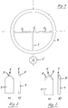
- Figure 1 shows a reticle that most manufacturers refer to as "reticle number ONE".
- the reticle consists of the middle vertical glass bar 1 with the tip 6 and the glass cross bars 3 and 4. Die radially extending bars 1 to 3 are integrally connected to a glass ring 4, which forms the outer contour of the reticle.
- the glass ring 4 with the glass beams 1 to 3 is worked out of a glass sheet. That is, the material of the glass sheet between the beams 1 to 3 and the ring 4 is e.g. removed by cutting or etching, so that the ring 4 and the bars 1 to 3 integrally connected therewith remain.
- the glass ring 4 with the glass beams 1 to 3 forms a light guide which receives its light from a light source 5, for example a lamp or an LED, which illuminates the ring 4.
- a light source 5 for example a lamp or an LED, which illuminates the ring 4.
- a glass fiber can also be connected to the ring 4.
- the tip 6 of the bar 1 is ground to form a triangular surface 7, which reflects or scatters the light from the light source 5 guided through the ring 4 into the beam 1 to the viewer, so that the surface 7 lights up as a target.
- the tip 6 is ground in a corresponding manner on its outer edge to the surfaces 8 and 9, through which the light is reflected or scattered to the viewer as a target in the form of an arrow.
Abstract
Description
Die Erfindung bezieht sich auf ein Zielfernrohr mit einem leuchtenden Absehen.The invention relates to a rifle scope with a luminous reticle.
Bei Jagdwaffen werden Zielfernrohre verwendet, die mit verschieden gestalteten Absehen ausgerüstet sind. Beim Jagen in der Morgen- oder Abenddämmerung ist oft das Absehen auf dem dunklen Wildkörper nicht zu erkennen. Dafür sind verschiedene Lösungen zur Beleuchtung der Absehen gefunden worden. Meist wird eine Strichplatte mit eingeätztem Absehen ganz oder teilweise zum Leuchten gebracht. Auch mit Glasfasern sind Lösungen im Gebrauch.Riflescopes with differently designed reticles are used for hunting weapons. When hunting at dawn or dusk, the reticle is often not visible on the dark game body. Various solutions for illuminating the reticles have been found for this. Usually a reticle with an etched reticle is made to glow in whole or in part. Solutions are also used with glass fibers.
Wird das Absehen in eine Glasplatte geätzt und die mit einem reflektierenden Medium ausgefüllte Einätzung von einer Lichtquelle zum Leuchten gebracht, tritt aus der Strichplatte Licht aus. Dieses unerwünschte Licht kann das Zielbild überstrahlen und ist für den Verwender störend. Ebenso wird durch die Glasplatte der Transmissionsgrad des Zielfernrohres herabgesetzt und damit dessen Leistung in der Dämmerung verringert. Wird auf das Absehen eine Glasfaser als Lichtleiter aufgebracht, muß diese so ausgerichtet und befestigt werden, daß der Punkt des austretenden Lichtes genau am Zielpunkt liegt. Das feine Ausrichten stellt dabei hohe Anforderungen an den Ausführenden.If the reticle is etched into a glass plate and the etching filled with a reflecting medium is illuminated by a light source, light emerges from the reticle. This unwanted light can outshine the target image and is annoying for the user. Likewise, the transmittance of the riflescope is reduced by the glass plate and thus its performance at dusk is reduced. If a glass fiber is attached to the reticle as a light guide, it must be aligned and attached so that the point of the emerging light is exactly at the target point. The fine alignment places high demands on the executors.
Aufgabe der Erfindung ist es, ein in der Herstellung einfaches leuchtendes Absehen ohne Überstrahlungen und störende Reflexe bereitzustellen.The object of the invention is to provide a reticle that is simple to produce without glare and disturbing reflections.
Dies wird erfindungsgemäß mit dem im Anspruch 1 angegebenen Zielfernrohr erreicht. In den Unteransprüchen sind vorteilhafte Ausgestaltungen der Erfindung wiedergegeben. Nach der Erfindung wird das Absehen aus einer Scheibe aus transparentem Material herausgearbeitet, insbesondere aus Glas. Das Herausarbeiten des transparenten Materials aus der Scheibe kann durch Schneiden, Schleifen und/oder Ätzen erfolgen.This is achieved according to the invention with the telescopic sight specified in
Dabei kann das gesamte Material herausgearbeitet werden, so daß ein Gerippe aus den Balken des Absehens sowie ein dem Umfang der Scheibe entsprechender Ring zurückbleibt, der die Balken einstückig trägt. Ein solches Gerippe kann dann gegebenenfalls auf einer Scheibe aus transparentem Material, also insbesondere Glas, durch Aufkleben befestigt werden. Es ist jedoch auch möglich, das Material nur zum Teil herauszuarbeiten, also abgesehen von dem dem Umfang der Scheibe entsprechenden Ring und den Balken des Absehens, die Schichtdicke der Scheibe zu reduzieren.The entire material can be worked out, so that a framework remains from the bars of the reticle and a ring corresponding to the circumference of the disc, which supports the bars in one piece. Such a framework can then optionally be attached to a pane of transparent material, in particular glass, by gluing. However, it is also possible to work out the material only in part, that is, apart from the ring corresponding to the circumference of the disk and the bars of the reticle, to reduce the layer thickness of the disk.
Das durch Herausarbeiten des transparenten Materials aus der Scheibe hergestellte Absehen bildet einen Lichtleiter, z.B. mit rechteckigem Querschnitt, ist also in der Wirkung ähnlich einer Glasfaser. Bestimmte Bereiche, wie der Ring und Teile der Balken, können mit einer lichtundurchlässigen Schicht versehen werden, um ein Überstrahlen und störende Reflexe auszuschließen.The reticle produced by working out the transparent material from the pane forms a light guide, e.g. with a rectangular cross-section, so its effect is similar to that of a glass fiber. Certain areas, such as the ring and parts of the beams, can be provided with an opaque layer to prevent overexposure and distracting reflections.
Nachstehend ist eine Ausführungsform des erfindungsgemäßen Absehens anhand der Zeichnung erläutert. Darin zeigen:
Figur 1 eine Draufsicht auf ein Absehen; und- Figur 2a und 2b sowie Figur 3a und Figur 3b den Bereich der Spitze eines gegenüber
Figur 1 stark vergrößert wiedergegebenen Balkens, jeweils in der Draufsicht und in der Seitenansicht nach einer ersten und einer zweiten Variante.
- Figure 1 is a plan view of a reticle; and
- 2a and 2b as well as FIG. 3a and FIG. 3b the area of the tip of a bar which is reproduced in a greatly enlarged manner compared to FIG. 1, in each case in a top view and in a side view according to a first and a second variant.
In Figur 1 ist ein Absehen dargestellt, das von den meisten Herstellern als "Absehen Nummer EINS" bezeichnet wird. Das Absehen besteht aus dem mittleren senkrechten Glasbalken 1 mit der Spitze 6 und den Glasquerbalken 3 und 4. Die radial verlaufenden Balken 1 bis 3 sind einstückig mit einem Glasring 4 verbunden, der die Außenkontur des Absehens bildet.Figure 1 shows a reticle that most manufacturers refer to as "reticle number ONE". The reticle consists of the middle
Der Glasring 4 mit den Glasbalken 1 bis 3 wird aus einer Glasscheibe herausgearbeitet. Das heißt, das Material der Glasscheibe zwischen den Balken 1 bis 3 und dem Ring 4 wird z.B. durch Herausschneiden oder Ätzen entfernt, so daß der Ring 4 und die damit einstückig verbundenen Balken 1 bis 3 zurückbleiben.The glass ring 4 with the
Der Glasring 4 mit den Glasbalken 1 bis 3 bildet einen Lichtleiter, der sein Licht von einer Lichtquelle 5 empfängt, beispielsweise einer Lampe oder einer LED, welche den Ring 4 anstrahlt. Auch kann eine Glasfaser an den Ring 4 angeschlossen sein.The glass ring 4 with the
Wie aus Figuren 2a und 2b hervorgeht, ist die Spitze 6 des Balkens 1 zu einer dreieckigen Fläche 7 abgeschliffen, die das über den Ring 4 in den Balken 1 geleitete Licht der Lichtquelle 5 zum Betrachter hin reflektiert bzw. streut, so daß die Fläche 7 als Zielmarke aufleuchtet.As can be seen from FIGS. 2a and 2b, the
Bei der Variante nach Figuren 3a und 3b ist die Spitze 6 in entsprechender Weise an ihrer Außenkante zu den Flächen 8 und 9 abgeschliffen, durch die das Licht zu dem Betrachter als Zielmarke in Form eines Pfeiles reflektiert bzw. gestreut wird.In the variant according to FIGS. 3a and 3b, the
Claims (7)
Applications Claiming Priority (2)
| Application Number | Priority Date | Filing Date | Title |
|---|---|---|---|
| DE9429382 | 1994-12-20 | ||
| DE9429382U | 1994-12-20 |
Publications (2)
| Publication Number | Publication Date |
|---|---|
| EP0718585A1 true EP0718585A1 (en) | 1996-06-26 |
| EP0718585B1 EP0718585B1 (en) | 1998-04-15 |
Family
ID=6918162
Family Applications (1)
| Application Number | Title | Priority Date | Filing Date |
|---|---|---|---|
| EP95120050A Expired - Lifetime EP0718585B1 (en) | 1994-12-20 | 1995-12-19 | Riflescope with illuminated reticle |
Country Status (3)
| Country | Link |
|---|---|
| EP (1) | EP0718585B1 (en) |
| AT (1) | ATE165152T1 (en) |
| DE (1) | DE59501905D1 (en) |
Cited By (8)
| Publication number | Priority date | Publication date | Assignee | Title |
|---|---|---|---|---|
| EP0918243A2 (en) * | 1997-11-20 | 1999-05-26 | Trijicon, Inc. | Optical sighting device |
| WO2002052218A1 (en) * | 2000-12-21 | 2002-07-04 | Saab Ab | A device, a use and a method for tracer stream simulation |
| US7250924B2 (en) | 2000-12-21 | 2007-07-31 | Saab Ab | Device a use and a method for tracer stream simulation |
| EP1847867A1 (en) * | 2006-04-19 | 2007-10-24 | Carl Zeiss Sports Optics GmbH | Illuminated aiming device for an observation instrument |
| US8619238B2 (en) | 2010-03-09 | 2013-12-31 | Leupold & Stevens, Inc. | Rangefinder for shooting device and method of aligning rangefinder to shooting device sight |
| CN108895899A (en) * | 2018-09-17 | 2018-11-27 | 李攀峰 | A kind of graduation pattern can be changed more colors and show double glass graticles and light structures |
| US10222628B2 (en) | 2016-02-29 | 2019-03-05 | Swarovski-Optik Kg. | Device for displaying a target mark |
| CN115128825A (en) * | 2022-07-19 | 2022-09-30 | 湖南华南光电(集团)有限责任公司 | Multi-color reticle device |
Families Citing this family (1)
| Publication number | Priority date | Publication date | Assignee | Title |
|---|---|---|---|---|
| ATE404901T1 (en) | 2004-10-29 | 2008-08-15 | Swarovski Optik Kg | RETICLE PLATE AND USE THEREOF FOR A RIFLE SCOPE |
Citations (6)
| Publication number | Priority date | Publication date | Assignee | Title |
|---|---|---|---|---|
| DE51205C (en) * | J. A. CHR. ADELSKÖLD, Lieutenant in der Königlich Schwedischen Marine, in Stockholm, Villagatan Nr. 2 | Night visors for firearms, Mefs instruments and the like, in which the visors are illuminated by means of electric light bulbs | ||
| CH38696A (en) * | 1907-01-07 | 1907-11-30 | Krupp Ag | Directional telescope with device for illuminating the sight mark |
| US2430469A (en) * | 1943-12-20 | 1947-11-11 | James C Karnes | Luminous gun sight |
| DE1915207A1 (en) * | 1968-11-12 | 1970-09-10 | Bushnell David P | Rifle scope with illuminated aiming device |
| GB2068584A (en) * | 1980-01-07 | 1981-08-12 | Arnold & Richter Kg | Reticule For Camera Viewfinder |
| DE3210834A1 (en) * | 1981-04-01 | 1983-01-05 | Thomas G. 38200 Nybro Bohl | AIMING AID FOR SHOTGUNS |
-
1995
- 1995-12-19 EP EP95120050A patent/EP0718585B1/en not_active Expired - Lifetime
- 1995-12-19 AT AT95120050T patent/ATE165152T1/en not_active IP Right Cessation
- 1995-12-19 DE DE59501905T patent/DE59501905D1/en not_active Expired - Fee Related
Patent Citations (6)
| Publication number | Priority date | Publication date | Assignee | Title |
|---|---|---|---|---|
| DE51205C (en) * | J. A. CHR. ADELSKÖLD, Lieutenant in der Königlich Schwedischen Marine, in Stockholm, Villagatan Nr. 2 | Night visors for firearms, Mefs instruments and the like, in which the visors are illuminated by means of electric light bulbs | ||
| CH38696A (en) * | 1907-01-07 | 1907-11-30 | Krupp Ag | Directional telescope with device for illuminating the sight mark |
| US2430469A (en) * | 1943-12-20 | 1947-11-11 | James C Karnes | Luminous gun sight |
| DE1915207A1 (en) * | 1968-11-12 | 1970-09-10 | Bushnell David P | Rifle scope with illuminated aiming device |
| GB2068584A (en) * | 1980-01-07 | 1981-08-12 | Arnold & Richter Kg | Reticule For Camera Viewfinder |
| DE3210834A1 (en) * | 1981-04-01 | 1983-01-05 | Thomas G. 38200 Nybro Bohl | AIMING AID FOR SHOTGUNS |
Cited By (11)
| Publication number | Priority date | Publication date | Assignee | Title |
|---|---|---|---|---|
| EP0918243A2 (en) * | 1997-11-20 | 1999-05-26 | Trijicon, Inc. | Optical sighting device |
| EP0918243A3 (en) * | 1997-11-20 | 2000-02-02 | Trijicon, Inc. | Optical sighting device |
| WO2002052218A1 (en) * | 2000-12-21 | 2002-07-04 | Saab Ab | A device, a use and a method for tracer stream simulation |
| US7250924B2 (en) | 2000-12-21 | 2007-07-31 | Saab Ab | Device a use and a method for tracer stream simulation |
| EP1847867A1 (en) * | 2006-04-19 | 2007-10-24 | Carl Zeiss Sports Optics GmbH | Illuminated aiming device for an observation instrument |
| US7471452B2 (en) | 2006-04-19 | 2008-12-30 | Carl Zeiss Sports Optics Gmbh | Illuminated aiming device for an observation instrument |
| US8619238B2 (en) | 2010-03-09 | 2013-12-31 | Leupold & Stevens, Inc. | Rangefinder for shooting device and method of aligning rangefinder to shooting device sight |
| US10222628B2 (en) | 2016-02-29 | 2019-03-05 | Swarovski-Optik Kg. | Device for displaying a target mark |
| CN108895899A (en) * | 2018-09-17 | 2018-11-27 | 李攀峰 | A kind of graduation pattern can be changed more colors and show double glass graticles and light structures |
| CN108895899B (en) * | 2018-09-17 | 2024-01-16 | 李攀峰 | Dual-glass reticle with changeable reticle pattern and multiple color display and illumination structure |
| CN115128825A (en) * | 2022-07-19 | 2022-09-30 | 湖南华南光电(集团)有限责任公司 | Multi-color reticle device |
Also Published As
| Publication number | Publication date |
|---|---|
| DE59501905D1 (en) | 1998-05-20 |
| EP0718585B1 (en) | 1998-04-15 |
| ATE165152T1 (en) | 1998-05-15 |
Similar Documents
| Publication | Publication Date | Title |
|---|---|---|
| DE3602262C2 (en) | Refractor element for a motor vehicle headlight for low beam or fog light | |
| EP0890785B1 (en) | Vehicle headlights | |
| DE3515809C2 (en) | ||
| DE3542292A1 (en) | Luminaire for a motor vehicle | |
| DE3102626A1 (en) | "PASSIVE ELECTROOPTICAL DISPLAY DEVICE" | |
| EP0780265A2 (en) | Vehicle rear light | |
| DE19844316A1 (en) | Illuminated display scale device | |
| DE19526023A1 (en) | Headlamp for motor vehicle | |
| EP0718585B1 (en) | Riflescope with illuminated reticle | |
| DE2908453C2 (en) | Signal light emitting colored light, in particular for vehicles | |
| EP0886163A2 (en) | Fiducial mark and optical system having a fiducial mark capable to be illuminated | |
| DE2552278A1 (en) | Illumination of fluidic crystal display - has optical fibre block between light and display rear and input and output surfaces at angle to axis | |
| DE19530950B4 (en) | Headlights for vehicles | |
| EP0404990B1 (en) | Motor vehicle light | |
| DE4205137A1 (en) | Flat hinge-mounted lamp e.g. for wall or ceiling - has diffuser with lamp in one edge and one side coated giving regular and diffuse reflecting areas | |
| EP1018053A1 (en) | Optical system for injecting laser radiation into an optical fibre and method for making same | |
| DE19606179A1 (en) | Outdoor display lettering illumination | |
| DE2649927A1 (en) | DEVICE FOR INTRODUCING LIGHT MARKERS IN THE BEAM PATH OF NIGHT VISION DEVICES | |
| EP1083452A1 (en) | Illumination system for an operation microscope | |
| DE4242580C2 (en) | Diffuser made of translucent material | |
| EP0969304B1 (en) | Optical adapter | |
| EP0741275B1 (en) | Optical aiding aid | |
| DE19926835C2 (en) | lamp | |
| DE864836C (en) | Anti-glare body for motor vehicle headlights | |
| DE19814478A1 (en) | Headlights for vehicles |
Legal Events
| Date | Code | Title | Description |
|---|---|---|---|
| PUAI | Public reference made under article 153(3) epc to a published international application that has entered the european phase |
Free format text: ORIGINAL CODE: 0009012 |
|
| AK | Designated contracting states |
Kind code of ref document: A1 Designated state(s): AT BE CH DE FR GB IT LI |
|
| 17P | Request for examination filed |
Effective date: 19960723 |
|
| 17Q | First examination report despatched |
Effective date: 19960919 |
|
| GRAG | Despatch of communication of intention to grant |
Free format text: ORIGINAL CODE: EPIDOS AGRA |
|
| GRAG | Despatch of communication of intention to grant |
Free format text: ORIGINAL CODE: EPIDOS AGRA |
|
| GRAH | Despatch of communication of intention to grant a patent |
Free format text: ORIGINAL CODE: EPIDOS IGRA |
|
| GRAH | Despatch of communication of intention to grant a patent |
Free format text: ORIGINAL CODE: EPIDOS IGRA |
|
| GRAA | (expected) grant |
Free format text: ORIGINAL CODE: 0009210 |
|
| AK | Designated contracting states |
Kind code of ref document: B1 Designated state(s): AT BE CH DE FR GB IT LI |
|
| REF | Corresponds to: |
Ref document number: 165152 Country of ref document: AT Date of ref document: 19980515 Kind code of ref document: T |
|
| REG | Reference to a national code |
Ref country code: CH Ref legal event code: NV Representative=s name: HUG INTERLIZENZ AG Ref country code: CH Ref legal event code: EP |
|
| ITF | It: translation for a ep patent filed |
Owner name: ING. LUIGI COLOBERTI |
|
| GBT | Gb: translation of ep patent filed (gb section 77(6)(a)/1977) |
Effective date: 19980415 |
|
| REF | Corresponds to: |
Ref document number: 59501905 Country of ref document: DE Date of ref document: 19980520 |
|
| ET | Fr: translation filed | ||
| PLBE | No opposition filed within time limit |
Free format text: ORIGINAL CODE: 0009261 |
|
| STAA | Information on the status of an ep patent application or granted ep patent |
Free format text: STATUS: NO OPPOSITION FILED WITHIN TIME LIMIT |
|
| 26N | No opposition filed | ||
| PGFP | Annual fee paid to national office [announced via postgrant information from national office to epo] |
Ref country code: GB Payment date: 20001204 Year of fee payment: 6 |
|
| PGFP | Annual fee paid to national office [announced via postgrant information from national office to epo] |
Ref country code: FR Payment date: 20001215 Year of fee payment: 6 |
|
| PGFP | Annual fee paid to national office [announced via postgrant information from national office to epo] |
Ref country code: CH Payment date: 20001221 Year of fee payment: 6 |
|
| PGFP | Annual fee paid to national office [announced via postgrant information from national office to epo] |
Ref country code: BE Payment date: 20001222 Year of fee payment: 6 Ref country code: AT Payment date: 20001222 Year of fee payment: 6 |
|
| PGFP | Annual fee paid to national office [announced via postgrant information from national office to epo] |
Ref country code: DE Payment date: 20010129 Year of fee payment: 6 |
|
| PG25 | Lapsed in a contracting state [announced via postgrant information from national office to epo] |
Ref country code: GB Free format text: LAPSE BECAUSE OF NON-PAYMENT OF DUE FEES Effective date: 20011219 Ref country code: AT Free format text: LAPSE BECAUSE OF NON-PAYMENT OF DUE FEES Effective date: 20011219 |
|
| PG25 | Lapsed in a contracting state [announced via postgrant information from national office to epo] |
Ref country code: LI Free format text: LAPSE BECAUSE OF NON-PAYMENT OF DUE FEES Effective date: 20011231 Ref country code: CH Free format text: LAPSE BECAUSE OF NON-PAYMENT OF DUE FEES Effective date: 20011231 Ref country code: BE Free format text: LAPSE BECAUSE OF NON-PAYMENT OF DUE FEES Effective date: 20011231 |
|
| REG | Reference to a national code |
Ref country code: GB Ref legal event code: IF02 |
|
| BERE | Be: lapsed |
Owner name: SWAROVSKI OPTIK K.G. Effective date: 20011231 |
|
| PG25 | Lapsed in a contracting state [announced via postgrant information from national office to epo] |
Ref country code: DE Free format text: LAPSE BECAUSE OF NON-PAYMENT OF DUE FEES Effective date: 20020702 |
|
| GBPC | Gb: european patent ceased through non-payment of renewal fee |
Effective date: 20011219 |
|
| REG | Reference to a national code |
Ref country code: CH Ref legal event code: PL |
|
| PG25 | Lapsed in a contracting state [announced via postgrant information from national office to epo] |
Ref country code: FR Free format text: LAPSE BECAUSE OF NON-PAYMENT OF DUE FEES Effective date: 20020830 |
|
| REG | Reference to a national code |
Ref country code: FR Ref legal event code: ST |
|
| PG25 | Lapsed in a contracting state [announced via postgrant information from national office to epo] |
Ref country code: IT Free format text: LAPSE BECAUSE OF NON-PAYMENT OF DUE FEES;WARNING: LAPSES OF ITALIAN PATENTS WITH EFFECTIVE DATE BEFORE 2007 MAY HAVE OCCURRED AT ANY TIME BEFORE 2007. THE CORRECT EFFECTIVE DATE MAY BE DIFFERENT FROM THE ONE RECORDED. Effective date: 20051219 |