EP0718580B1 - Wärmetauscher und Verfahren zu seiner Herstellung - Google Patents
Wärmetauscher und Verfahren zu seiner Herstellung Download PDFInfo
- Publication number
- EP0718580B1 EP0718580B1 EP95120018A EP95120018A EP0718580B1 EP 0718580 B1 EP0718580 B1 EP 0718580B1 EP 95120018 A EP95120018 A EP 95120018A EP 95120018 A EP95120018 A EP 95120018A EP 0718580 B1 EP0718580 B1 EP 0718580B1
- Authority
- EP
- European Patent Office
- Prior art keywords
- tank
- base plate
- metal plate
- folded
- heat exchanger
- Prior art date
- Legal status (The legal status is an assumption and is not a legal conclusion. Google has not performed a legal analysis and makes no representation as to the accuracy of the status listed.)
- Expired - Lifetime
Links
Images




Classifications
-
- F—MECHANICAL ENGINEERING; LIGHTING; HEATING; WEAPONS; BLASTING
- F28—HEAT EXCHANGE IN GENERAL
- F28F—DETAILS OF HEAT-EXCHANGE AND HEAT-TRANSFER APPARATUS, OF GENERAL APPLICATION
- F28F9/00—Casings; Header boxes; Auxiliary supports for elements; Auxiliary members within casings
- F28F9/02—Header boxes; End plates
- F28F9/0219—Arrangements for sealing end plates into casing or header box; Header box sub-elements
- F28F9/0224—Header boxes formed by sealing end plates into covers
-
- Y—GENERAL TAGGING OF NEW TECHNOLOGICAL DEVELOPMENTS; GENERAL TAGGING OF CROSS-SECTIONAL TECHNOLOGIES SPANNING OVER SEVERAL SECTIONS OF THE IPC; TECHNICAL SUBJECTS COVERED BY FORMER USPC CROSS-REFERENCE ART COLLECTIONS [XRACs] AND DIGESTS
- Y10—TECHNICAL SUBJECTS COVERED BY FORMER USPC
- Y10S—TECHNICAL SUBJECTS COVERED BY FORMER USPC CROSS-REFERENCE ART COLLECTIONS [XRACs] AND DIGESTS
- Y10S165/00—Heat exchange
- Y10S165/454—Heat exchange having side-by-side conduits structure or conduit section
- Y10S165/471—Plural parallel conduits joined by manifold
- Y10S165/489—Two piece header structure
-
- Y—GENERAL TAGGING OF NEW TECHNOLOGICAL DEVELOPMENTS; GENERAL TAGGING OF CROSS-SECTIONAL TECHNOLOGIES SPANNING OVER SEVERAL SECTIONS OF THE IPC; TECHNICAL SUBJECTS COVERED BY FORMER USPC CROSS-REFERENCE ART COLLECTIONS [XRACs] AND DIGESTS
- Y10—TECHNICAL SUBJECTS COVERED BY FORMER USPC
- Y10T—TECHNICAL SUBJECTS COVERED BY FORMER US CLASSIFICATION
- Y10T29/00—Metal working
- Y10T29/49—Method of mechanical manufacture
- Y10T29/4935—Heat exchanger or boiler making
- Y10T29/49389—Header or manifold making
Definitions
- the invention relates to a heat exchanger according to the preamble of claim 1 and to a method for manufacturing such a heat exchanger.
- Such a heat exchanger is known from GB-A-2 098 313 or DE-A-43 19 542.
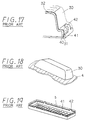
- JP-U-63-52 88 Such a kind of a heat exchanger is disclosed in JP-U-63-52 88. Assembling structures of a tank 30 and a base plate 40 are shown in Fig. 17, and the tank 30 and the base plate 40 are made of metal such as aluminum or the like.
- Fig. 17 several claws 42 for fixing a tank temporarily are provided on an end portion 41 of the base plate 40. After the base plate 40 and the tank 30 are assembled together, the claws 42 are bent to be in contact with a stepped outer wall surface of the end portion 31 of the tank 30, and both the tank 30 and the base plate 40 are thereby fixed temporarily.
- the temporary assembled body such as the tank 30 or the like is heated up to a brazing temperature in a heating furnace, a brazing material 32 on a surface of the tank 30 is melted and the tank 30 and the base plate 40 are joined by brazing.
- the tank 30 and the base plate 40 are generally made of a metal flat plate such as aluminum or the like by a drawing process.
- the drawing process can produce many parts within a short time period and has an advantage of high productivity.
- the drawing process provides a material having a larger shape than a finished shape of the parts, and excess portions (scrap portions) of the parts should be removed after the drawing process.
- a portion "a 0 " of the tank 30 corresponds to the scrap portion, and cost for the material is increased undesirably.
- Another object of the present invention is to provide a heat exchanger which can be assembled from a tank and a base plate without using a process for crimping claws and a method for manufacturing the same.
- the tank and the base plate are structured by folding unfolded plates and by connecting the folded portions. Therefore, the scrap portion can be greatly reduced as compared to a heat exchanger produced by the conventional drawing process, and the cost for the material can be thereby reduced.
- a method for manufacturing a heat exchanger includes steps of: cutting a metal plate to make an unfolded metal plate for forming a box-shaped tank; cutting a metal plate to make an unfolded metal plate for forming a base plate and making a hole into which a tube is inserted at the base plate; folding the metal plate for the tank along a predetermined folding line to form the tank in a box shape having an opening; folding the metal plate for the base plate along a predetermined folding line to form the base plate in a box shape having an opening; inserting an end portion of the tube into the hole of the base plate and assembling the tank with the base plate to cover the opening of the tank; and brazing the tank, the base plate and the tube integrally to make an assembled body.
- the above heat exchanger can be easily manufactured.
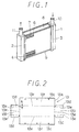
- Figs. 1 through 6 illustrate a first embodiment where the present invention is applied to a heater core (heat exchanger) of an automotive air conditioning apparatus.
- tanks 1 and 2 are formed into generally a U-shape in cross-sections thereof.
- Base plates 3 and 4 to which opening end portions of the tanks 1 and 2 are joined, are also formed into generally a U-shape in cross-sections thereof.
- a lot of flat-shaped holes 5 for receiving tubes are provided in such a manner that a longitudinal direction of the holes 5 for inserting the tubes is parallel to a short side direction of the base plates 3 and 4.
- a cross-section of a flat tube 6 is formed into a flat shape, and each end portion of the flat tube 6 is inserted into and joined with the tube receiving holes 5 of the base plates 3 and 4.
- corrugated fins 7 are formed into a wavy shape and disposed between the flat tubes 6 to be joined with the flat tubes 6.
- End plates 8 and 9 are disposed at both side portions of a core portion (heat exchanging portion) having the flat tubes 6 and the corrugated fins 7 and are joined with the base plates 3 and 4 and the corrugated fin 7.
- An inlet pipe 10 for warm water is inserted into and connected to a hole (not shown) provided at the tank 1.
- An outlet pipe 11 for cooled water (engine cooling water) is inserted and connected to a hole (not shown) provided at the tank 2. Since a structure of the heat exchanger in Fig. 1 is a symmetrical structure with respect to left and right directions, the positions of inlet pipe 10 and the outlet pipe 11 may be interposed.
- the heater core shown in Fig. 1 is structured as an aluminum heat exchanger integrally joined by brazing.
- the corrugated fin 7 and the inlet pipe 10 are made of aluminum bare material (A 3000 series) with which a brazing material is not cladded, other members (1, 2, 3, 4, 6, 8, 9) are made of an aluminum cladded material in which a brazing material (A 4000 series) is cladded at both sides of the aluminum core material (A 3000 series).
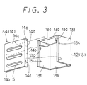
- Fig. 2 is a view illustrating an unfolded state of a metal plate forming the tanks 1 and 2.
- An unfolded metal plate 13 has a rectangular body portion 13a and first folded portions 13f are formed at the body portion 13a along a long side portion thereof. Second folded portions 13b protruding with an ear-like shape from the short side portion of the body portion 13a are formed.
- a plurality of semicircular protrusions 13c are formed at portions near each long end portion of the first folded portions 13f formed in a vertical direction of the body portion 13a.
- Joint surfaces 13d for ensuring brazing by increasing a joint area to be brazed are formed at both outer edge portions formed in a vertical direction of the second folded portions 13b having the ear-like shape.
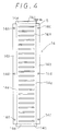
- the unfolded metal plate 13 for the tank is formed into a tank shape shown in Fig. 3, i.e., a tank shape (box shape) having a U-shaped cross section, where one end side is open and another end side closed, by folding the first and the second folded portions 13f and 13b and the joint surface 13d at a ridgeline 13e shown with dotted lines in Fig. 2.
- a tank shape box shape having a U-shaped cross section, where one end side is open and another end side closed
- the joint surfaces 13d of the second folded portions 13b increase the brazing area by being in contact with inner side surfaces of the first folded portions 13f.
- the ridgeline 13e of the first folded portions 13f is offset outwardly from a position of the ridgeline 13e of the joint surfaces 13d by a plate thickness d1 of the unfolded metal plate 13.
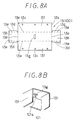
- Fig. 4 is a view illustrating an unfolded state of the metal plate forming the base plates 3 and 4.
- An unfolded metal plate 14 for the base plates has the same shape as the unfolded metal plate 13 for the tank and has the rectangular body portion 14a, and first folded portions 14b are formed along a long side portion of the body portion 14a.
- Second folded portions 14c are formed to protrude from short side portions of the body portion 14a.
- a plurality of semicircular concave portions are formed at positions corresponding to the semicircular protrusions 13c at the first folded portions 14b of the body portions 14a.
- a dotted line 14e illustrates a ridgeline as a folding position of the first and the second folded portions 14b and 14c.
- End portions in the longitudinal direction of the second folded portions 14c are offset outwardly from the dotted line 14e of the first folded portions 14b by a plate thickness d2 of the unfolded metal plate 14. Therefore, after folding the first and the second folded portions 14b and 14c, the second folded portions 14c can be folded on the end surface of the first folded portions 14b (see Fig. 3). Thus, the second folded portions 14c can be securely brazed on the end surface of the first folded portions 14b.
- the metal plate After cutting the metal plate into the unfolded shape shown in Fig. 4 by the pressing process, by folding the first and the second folded portions 14b and 14c at the dotted line 14e, the metal plate is formed into a shape shown in Fig. 3, i.e., a box shape in which one end side is closed and another end side is open.
- the second folded portions 14c are folded on the end surface of the first folded portions 14b, and a brazing area of the first and the second folded portions 14b and 14c is thereby obtained.
- Fig. 3 is an exploded perspective view illustrating a structure of the tanks 1 and 2 formed by the unfolded metal plates 13 and 14 and the base plates 3 and 4.
- the tanks 1 and 2 and the base plates 3 and 4 are assembled in such a manner that the first and the second folded portions 13f and 13b of the tanks 1 and 2 are inserted into inner periphery sides of the first and the second folded portion 14b and 14c of the base plates 3 and 4.
- an assembled state of the tanks 1 and 2 and the base plates 3 and 4 can be maintained by fitting the semicircular protrusions 13c of the tanks 1 and 2 into the semicircular concave portions 14c of the base plates 3 and 4, and therefore, the tanks 1 and 2 can be prevented from dropping off from the base plates 3 and 4 after being assembled together.
- FIG. 5A through 5F illustrate a process for manufacturing an individual part of heat exchanging component parts and an assembly of the core portion.
- Fig. 5A illustrates a roller forming process of the corrugated fin 7.
- Fig. 5B illustrates a roller forming process of the flat tube 6.
- Fig. 5C illustrates a roller forming process of the upper and lower end plates 8 and 9.
- Fig. 5D illustrates a process for forming the base plates 3 and 4 from the unfolded metal plate 14 by a folding process.
- Fig. 5E illustrates a process for forming the tanks 1 and 2 from the unfolded metal plate 13 by the folding process.
- Fig. 5F illustrates a process for assembling a core portion A by assembling parts other than the tanks 1 and 2 such as the base plates 3 and 4, the flat tube 6, the corrugated fin 7 and the end plates 8 and 9. Specifically, the flat tubes 6 and the corrugated fins 7 are alternately laminated together. After the end plates 8 and 9 are assembled on each of the upper and lower end portions of the laminated body, the base plates 3 and 4 are assembled on the assembled body.
- Figs. 6A through 6C illustrate processes after the process illustrated in Fig. 5F.
- Fig. 6A illustrates a parts assembling process in which an assembly of an overall heat exchanger is completed by assembling the tanks 1 and 2 and the inlet and the outlet pipes 10 and 11 to the core portion A in Fig. 5F.
- Fig. 6B illustrates a process for injecting the flux from a nozzle C to the assembled body B which has been completed to improve brazing performance.
- the flux removes an oxide film interrupting the brazing of aluminum from each part surface of the assembled body B and prevents the surfaces from re-oxidizing in the heating furnace for brazing.
- Fig. 6C is a process for integrally brazing the assembled body B by carrying the assembled body B of the heat exchanger into a heating furnace D by a conveyor E and by heating up the assembled body B to a specified temperature over a melting point of the brazing material in the heating furnace D.
- the heat exchanging structure shown in Fig. 1 is completed by the unit brazing.
- each of the tanks 1 and 2 has a folded structure formed from the unfolded shape, the folded portion can be joined securely by brazing with joint surfaces 13d provided at the tanks 1 and 2.
- the second folded portions 14c are folded on the end surfaces of the first folded portions 14b.
- the first and the second folded portions 14b and 14c can be securely joined by brazing the contacting portions of the first and the second folded portions 14b and 14c.
- a heat exchanger is structured as one-way flowing type (full pass) in which warm water flowing from the inlet pipe 10 provided on the tank 1 flows in the outlet pipe 11 provided on the tank 2 through the flat tube 6 and flows out from the outlet pipe 11.
- the present invention is applied to a heat exchanger in which a flow of such warm water makes a U-turn in the heat exchanging portion.
- a partition member 101 is disposed at a central position in a width direction of a tank 100 (an upper tank in Fig. 7) and an inside of the tank 100 is divided into two chambers 102 and 103 by the partition 101.
- An inlet pipe 10 is provided on the chamber 102 and an outlet pipe 11 is provided on the chamber 103.
- warm water flowing from the inlet pipe 10 to the outlet pipe 11 of the tank 100 flows into the other lower tank 104 through a tube 6 at a left half side.
- the warm water makes a U-turn and flows in the chamber 103 of the tank 100 through the tube 6 at a right half side and flows out toward the outside from the outlet pipe 11.
- Fig. 8A illustrates the unfolded metal plate 13 for a tank corresponding to Fig. 2.
- a hole 13g is provided at a central portion of the body portion 13a and a protrusion 101a of the partition member 101 which is separated from the tank 100 and made of metal such as aluminum or the like is fitted into the hole 13g (refer to Fig. 8B). Therefore, while being prevented from falling, the partition member 101 is joined between the tank 100 and the base plate 3 by brazing.
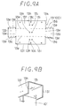
- FIGs. 9A and 9B illustrate a modification of this embodiment.
- a pair of protrusions 13h and 13i formed at a slightly larger interval than a plate thickness "t" of the partition member 101 is provided at a plurality of places at a central portion of the body portion 13a of the unfolded metal plate 13 for the tank.
- the partition member 101 is joined between the tank 100 and the base plate 3 by brazing while being prevented from falling.
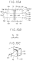
- FIGs. 10A through 10C illustrate another modification of this embodiment.
- a pair of protrusions 13j and 13k extending with a belt-like shape are formed at a slightly larger interval than the plate thickness "t" of the partition member 101.
- the partition member 101 is joined between the tank 100 and the base plate 3 by brazing while being prevented from falling.
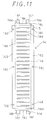
- Fig. 11 illustrates the unfolded metal plate 14 for the base plate corresponding to Fig. 4.
- a pair of claw pieces 14f extending outwardly are provided at two places at the second folded portion 14c of the metal plate 14.
- Fig. 7 by folding the claw pieces 14f on outer surfaces of both end portions of the base plates 3 and 4, an assembly position of the end plates 8 and 9 is held.
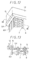
- a concave portion 15 (refer to Fig. 13) which is slightly larger than a cross-sectional shape of the end plates 8 and 9 is provided at an outer side from the tube inserting hole 5 at a bottom wall surface of the base plates 3 and 4.
- the concave portion 15 is formed across generally a full length in the width direction of the bottom wall surface of the base plates 3 and 4, and the width of the concave portion 15 is a slightly larger than that of the end plates 8 and 9.
- End portions of the end plates 8 and 9 are inserted into the concave portion 15 to hold the assembly position of the end plates 8 and 9.
- the holding mechanism of the end plate assembly position is applied as described above.
- the end portions of the end plates 8 and 9 are inserted into the concave portion 15 formed across generally the full length in the width direction of the bottom wall surface of the base plates 3 and 4 and the assembly position of the end plates 8 and 9 are held. Therefore, even though an assembling reaction force of the heat exchanging portion is applied to the aluminum base plates 3 and 4 from the end plates 8 and 9 of the steel plates, the reaction force can be received at the bottom wall surface as a whole of the base plates 3 and 4. Since stress concentration is not caused partially, the brazing malfunction due to deformation of the aluminum base plates 3 and 4 can be prevented.
- a difference of melting points between aluminum base metal constructing the tank 1 and 2 and a brazing material (Al-Si series alloy) cladded on the base material is small. Therefore, when the aluminum base material is heated up to the melting point of the brazing material at brazing, the aluminum base material weakens.
- the second folded portion 13b of the unfolded metal plate 13 for the tank may be deformed by its weight and a folding angle of the second folded portion 13b cannot be maintained at 90° .
- the second folded portion 13b may fall inwardly toward or fall outwardly from a tank box-shape.
- the second folded portion 13b and the first folded portion 13f cannot be brazed appropriately.
- a semicircular protrusion 13m is formed at either the joint portion 13d or the first folded portion 13f (at the joint portion 13d in the embodiment shown in Figs. 14A and 14B) and a semicircular concave portion 13n into which the protrusion 13m is fitted is formed at the other of the joint potion 13d and the first folded portion 13f (at the joint portion 13f in Figs. 14A and 14B).
- the folding angle of the second folded portion 13b can be maintained at 90° .
- the folded portion of the first and the second folded portions 13b and 13f can be prevented from returning due to elasticity of aluminum (spring back).
- an inserting hole 13p of the inlet and the outlet pipes 10 and 11 is open at the second folded portion 13b of the unfolded metal plate 13 for the tank, and the inlet and the outlet pipes 10 and 11 are inserted into the inserting hole 13p.
- a bending moment is applied to the second folded portion 13b by weights of the inlet and the outlet pipes 10 and 11.
- the second folded portion 13b at high temperature heated by brazing is influenced by the bending moment, and therefore, the second folded portion 13b may fall into the interior of the box-shape.
- a protrusion 14g protruding toward the second folded portion 13b of the unfolded metal plate 13 for the tank is formed at a portion adjacent to the second folded portion 14c of the unfolded metal plate 14 for the base plates.
- a concave portion into which a tip end of the second folded portion 13b of the unfolded metal plate 13 for the tank is fitted is formed between the protrusion 14g and the second folded portion 14c.
- the semicircular protrusion 13c is provided at the tanks 1 and 2 and a semicircular concave portion 14d is provided at the base plates 3 and 4, and the protrusion 13c is fitted into the concave portion 14c.
- a semicircular protrusion is provided at the base plates 3 and 4 and a semicircular concave portion may be provided at the tanks 1 and 2. That is to say, at the joint portion of the tanks 1 and 2 and the base plates 3 and 4, a protrusion is provided at one side and a concave portion into which the protrusion is fitted is provided at the other side.
- the first folded portion 14b can be folded on the end surface of the second folded portion 14c in a manner to be in contact with the end surface of the second folded portion 14c.
- the end portion in the longitudinal direction of the second folded portion 14c needs to be shifted by an offset of the plate thickness d2 of the unfolded metal plate 14 inwardly from the folding position 14e of the first folded portion 14b.
- the present invention is not limited to a heater core for a heater and can be used widely in a heat exchanger for an automotive radiator or the like.
Landscapes
- Engineering & Computer Science (AREA)
- Physics & Mathematics (AREA)
- Thermal Sciences (AREA)
- Mechanical Engineering (AREA)
- General Engineering & Computer Science (AREA)
- Heat-Exchange Devices With Radiators And Conduit Assemblies (AREA)
- Details Of Heat-Exchange And Heat-Transfer (AREA)
Claims (8)
- Wärmetauscher, umfassend:dadurch gekennzeichnet, daßeinen Behälter (1, 2), der in einer kastenförmigen Gestalt ausgebildet ist, wobei der Behälter (1, 2) umgefaltete Bereiche zur Bildung einer Öffnung aufweist;eine Basisplatte (3, 4), die in einer kastenförmigen Gestalt ausgebildet ist und die Öffnung des Behälters (1, 2) abdeckt, wobei die Basispiatte (3, 4) umgefaltete Bereiche, die an den umgefalteten Bereichen des Behälters (1, 2) befestigt sind, und einen Bodenbereich aufweist, der Löcher (5) aufweist; undRöhrchen (6), die in die Löcher der Basisplatte (3, 4) eingesetzt und an der Basisplatte (3, 4) befestigt sind, um eine Fluidverbindung mit dem Behälter (1, 2) aufrechtzuerhalten,wobei sowohl der Behälter (1, 2) als auch die Basisplatte (3, 4) aus einer nicht umgefalteten Metallplatte (13, 14) durch Falten hergestellt ist,
die nicht umgefaltete Metallplatte (13, 14) aufweist:einen Körperbereich (13a, 14a), der in einer rechteckigen Gestalt mit einem Paar langer Seiten und einem Paar kurzer Seiten ausgebildet ist;ein Paar erste umgefaltete Bereiche (13f, 14b), die entlang der langen Seiten des Körperbereichs (13a, 14a) ausgebildet sind; undein Paar zweite umgefaltete Bereiche (13b, 14b), die entlang der kurzen Seiten des Körperbereichs (13a, 13a) ausgebildet sind,wobei die ersten und die zweiten umgefalteten Bereiche (13f, 13b, 14b, 14c) zur Bildung einer kastenförmigen Gestalt umgefaltet und verbunden sind und wobei die nicht umgefaltete Metallplatte (13, 14) für die Basisplatte (3, 4) eine Umfaltposition an dem ersten umgefalteten Bereich (13f) aufweist und Endbereiche des zweiten umgefalteten Bereichs (13b) in Längsrichtung um eine Versetzung in der Größe der Plattendicke in Hinblick auf die Umfaltposition des ersten umgefalteten Bereichs (13f) verschoben sind. - Wärmetauscher nach Anspruch 1, wobei der umgefaltete Bereich (13b) der nicht umgefalteten Metallplatte (13, 14) eine Verbindungsfläche (13d) zur Vergrößerung des Verbindungsbereichs zwischen dem Behälter (1, 2) und der Basisplatte (3, 4) aufweist.
- Wärmetauscher nach Anspruch 2, wobei die Verbindungsfläche (13d) an dem zweiten umgefalteten Bereich (13b) der nicht umgefalteten Metallplatte (13, 14) für den Behälter (1, 2) vorgesehen ist.
- Wärmetauscher nach Anspruch 3, wobei die Verbindungsfläche (13d) mit dem ersten umgefalteten Bereich (13f) der nicht umgefalteten Metallplatte (13, 14) für den Behälter (1, 2) in Berührung gebracht ist und an dem Berührungsbereich zwischen der Verbindungsfläche (13d) und dem ersten umgefalteten Bereich (13f) ein Vorsprung (13m) an einer Seite vorgesehen ist und ein konkaver Bereich (13n), in dem der Vorsprung (13m) eingesetzt ist, an der anderen Seite vorgesehen ist.
- Wärmetauscher nach Anspruch 4, wobei an der Verbindungsfläche zwischen dem Behälter (1, 2) und der Basisplatte (3, 4) ein Vorsprung (13c) an einer Seite der Verbindungsfläche vorgesehen ist und ein konkaver Bereich (14d), in den der Vorsprung (13c) eingesetzt ist, an der anderen Seite der Verbindungsfläche vorgesehen ist.
- Wärmetauscher nach Anspruch 5, wobei:wobei ein Spitzenbereich zwischen dem zweiten umgefalteten Bereich (13b) der nicht umgefalteten Metallplatte (13, 14) für die Basisplatte (3, 4) und dem Vorsprung (14g) gehalten ist.der zweite umgefaltete Bereich (13b) der nicht umgefalteten Metallplatte (13, 14) für den Behälter (1, 2) mit dem Einlaß- und dem Auslaßrohr (10, 11) für ein Fluid in Verbindung steht unddie nicht umgefaltete Metallplatte (13, 14) für die Basisplatte (3, 4) einen Vorsprung (14g) in der Nähe des zweiten umgefalteten Bereichs (13b) aufweist,
- Wärmetauscher nach Anspruch 3, wobei die nicht umgefaltete Metallplatte für den Behälter (1, 2) erste und zweite Umfaltpositionen der Verbindungsflächen (13d) der ersten und zweiten umgefalteten Bereiche (13f, 14c) aufweist und die zweite Umfaltposition um eine Versetzung in der Größe der Plattendicke in Hinblick auf die erste Umfaltposition des ersten umgefalteten Bereichs (13f) verschoben ist.
- Verfahren zur Herstellung eines Wärmetauschers, der einen kastenförmigen Behälter (1, 2), eine kastenförmige Basisplatte (3, 4) und Röhrchen (6) aufweist, wobei das Verfahren die nachfolgend angegebenen Schritte umfaßt:Zuschneiden einer Metallplatte zur Herstellung einer nicht umgefalteten Metallplatte (13, 14) zur Ausbildung des kastenförmigen Behälters (1, 2);Zuschneiden einer Metallplatte zur Herstellung einer nicht umgefalteten Metallplatte zur Bildung der Basisplatte (3, 4) und Herstellen von Löchern (5), in die die Röhrchen (6) an der Basisplatte (3, 4) eingesetzt werden;Umfalten der Metallplatte für den Behälter (1, 2) entlang einer vorbestimmten Faltlinie zur Ausbildung des Behälters (1, 2) in einer kastenförmigen Gestalt mit einer Öffnung;Umfalten der Metallplatte für die Basisplatte (3, 4) entlang einer vorbestimmten Faltlinie zur Ausbildung der Basisplatte (3, 4) in einer kastenförmigen Gestalt mit einer Öffnung;Einsetzen eines Endbereichs der Röhrchen (6) in die Löcher (5) der Basisplatte (3, 4) und Zusammenbauen des Behälters (1, 2) mit der Basisplatte (3, 4), um die Öffnung des Behälters (1, 2) abzudecken; undVerlöten des Behälters (1, 2) und der Basisplatte (3, 4) und der Röhrchen (6) in einstückiger Weise, um einen zusammengebauten Körper herzustellen.
Applications Claiming Priority (6)
| Application Number | Priority Date | Filing Date | Title |
|---|---|---|---|
| JP31615094 | 1994-12-20 | ||
| JP31615094 | 1994-12-20 | ||
| JP316150/94 | 1994-12-20 | ||
| JP27301195 | 1995-10-20 | ||
| JP27301195A JP3624486B2 (ja) | 1994-12-20 | 1995-10-20 | 熱交換器およびその製法 |
| JP273011/95 | 1995-10-20 |
Publications (2)
| Publication Number | Publication Date |
|---|---|
| EP0718580A1 EP0718580A1 (de) | 1996-06-26 |
| EP0718580B1 true EP0718580B1 (de) | 1999-09-01 |
Family
ID=26550477
Family Applications (1)
| Application Number | Title | Priority Date | Filing Date |
|---|---|---|---|
| EP95120018A Expired - Lifetime EP0718580B1 (de) | 1994-12-20 | 1995-12-19 | Wärmetauscher und Verfahren zu seiner Herstellung |
Country Status (8)
| Country | Link |
|---|---|
| US (1) | US5678628A (de) |
| EP (1) | EP0718580B1 (de) |
| JP (1) | JP3624486B2 (de) |
| KR (1) | KR100268404B1 (de) |
| CN (1) | CN1086804C (de) |
| AU (1) | AU702047B2 (de) |
| DE (1) | DE69511835T2 (de) |
| TW (1) | TW311985B (de) |
Families Citing this family (34)
| Publication number | Priority date | Publication date | Assignee | Title |
|---|---|---|---|---|
| JP3674189B2 (ja) * | 1996-10-23 | 2005-07-20 | 株式会社デンソー | 熱交換器 |
| US6178292B1 (en) | 1997-02-06 | 2001-01-23 | Denso Corporation | Core unit of heat exchanger having electric heater |
| JPH11148794A (ja) | 1997-11-14 | 1999-06-02 | Zexel:Kk | 熱交換器 |
| FR2781280B1 (fr) * | 1998-07-17 | 2000-09-22 | Valeo Climatisation | Ensemble boite a fluide-collecteur pour echangeur de chaleur, en particulier de vehicule automobile |
| DE69909408T2 (de) * | 1998-11-27 | 2004-05-19 | Calsonic Kansei Corp. | Wasserkasten für Wärmetauscher |
| US6450253B1 (en) | 1998-11-27 | 2002-09-17 | Calsonic Kansei Corporation | Tank of heat exchanger |
| JP4161446B2 (ja) * | 1999-01-28 | 2008-10-08 | 株式会社デンソー | 熱交換器 |
| US6247232B1 (en) * | 1999-03-10 | 2001-06-19 | Transpro, Inc. | Method of manufacturing a welded heat exchanger with grommet construction |
| FR2805606B1 (fr) * | 2000-02-24 | 2002-07-05 | Valeo Thermique Moteur Sa | Boite collectrice a tubulure integree pour echangeur de chaleur |
| ITTO20010629A1 (it) * | 2001-06-29 | 2002-12-29 | Magneti Marelli Climat Srl | Condensatore per impianti di condizionamento d'aria di veicoli. |
| DE10132485B4 (de) * | 2001-07-05 | 2018-06-28 | Mahle International Gmbh | Sammelkasten für einen Wärmetauscher |
| JP4766787B2 (ja) * | 2001-07-06 | 2011-09-07 | 株式会社ティラド | 熱交換器のタンク構造 |
| US6675883B1 (en) | 2002-07-08 | 2004-01-13 | Modine Manufacturing Company | Manifold for heat exchanger |
| FR2860063A1 (fr) * | 2003-09-23 | 2005-03-25 | Valeo Climatisation | Procede d'assemblage d'une boite collectrice sur un collecteur d'un echangeur de chaleur, et assemblage ainsi obtenu |
| US7059050B2 (en) * | 2004-01-08 | 2006-06-13 | Delphi Technologies, Inc. | One piece integral reinforcement with angled end caps to facilitate assembly to core |
| US20050161207A1 (en) * | 2004-01-26 | 2005-07-28 | Valeo, Inc. | Heat exchanger manifold with formed corner joint |
| BRPI0513380A (pt) * | 2004-07-16 | 2008-05-06 | Behr Gmbh & Co Kg | transmissor de calor, caixa para alojamento de um fluindo para um transmissor de calor bem como processo para fabricação de uma tal caixa |
| EP1701126A1 (de) * | 2005-02-14 | 2006-09-13 | Valeo Systemes Thermiques | Verfahren für den Zusammenbau eines Sammlers auf eine Sammlerplatte eines Wärmetauschers und dadurch gekriegter Zusammenbau |
| DE102005054043A1 (de) * | 2005-11-12 | 2007-05-16 | Modine Mfg Co | Ganz-Metall-Wärmetauscher |
| FR2894020A1 (fr) * | 2005-11-30 | 2007-06-01 | Valeo Systemes Thermiques | Boite collectrice pour un echangeur de chaleur et echangeur comportant une telle boite collectrice |
| US7798206B2 (en) | 2006-02-07 | 2010-09-21 | Showa Denko K.K. | Heat exchanger and method of manufacturing the same |
| JP4861844B2 (ja) * | 2006-02-07 | 2012-01-25 | 昭和電工株式会社 | 熱交換器およびその製造方法 |
| US7874349B2 (en) | 2006-03-16 | 2011-01-25 | Visteon Global Technologies, Inc. | Heat exchanger tank |
| DE102006057031A1 (de) * | 2006-12-04 | 2008-06-05 | Behr Gmbh & Co. Kg | Kasten zur Aufnahme eines Fluids für einen Wärmeübertrager sowie Verfahren zur Herstellung eines derartigen Kastens, Wärmeübertrager |
| US20080156455A1 (en) * | 2006-12-14 | 2008-07-03 | Powers Michael V | Heat exchanger manifolds with retention tabs |
| US7673672B2 (en) * | 2006-12-15 | 2010-03-09 | Denso International America, Inc. | Non-brazed insert for heat exchanger |
| EP2017563B1 (de) * | 2007-07-17 | 2009-09-23 | Delphi Technologies, Inc. | Rohrboden und Herstellungsverfahren dafür |
| KR20090047906A (ko) * | 2007-11-08 | 2009-05-13 | 주식회사 경동나비엔 | 평면형 열교환기 |
| KR101086917B1 (ko) * | 2009-04-20 | 2011-11-29 | 주식회사 경동나비엔 | 열교환기 |
| DE102011013043B4 (de) * | 2010-03-08 | 2025-04-30 | Denso Corporation | Wärmetauscher |
| DE102010040638A1 (de) * | 2010-09-13 | 2012-03-15 | Behr Gmbh & Co. Kg | Kasten und Verfahren zur Herstellung eines Kastens |
| DE102014213758A1 (de) * | 2014-07-15 | 2016-01-21 | Mahle International Gmbh | Rohrboden und Wärmeübertrager |
| JP6533931B2 (ja) * | 2014-12-10 | 2019-06-26 | 有限会社和氣製作所 | 箱状部材の製造方法 |
| US10697716B2 (en) * | 2017-08-30 | 2020-06-30 | Mahle International Gmbh | Heat exchanger and header plate for heat exchanger |
Family Cites Families (9)
| Publication number | Priority date | Publication date | Assignee | Title |
|---|---|---|---|---|
| US3113615A (en) * | 1961-05-08 | 1963-12-10 | Modine Mfg Co | Heat exchanger header construction |
| US3866675A (en) * | 1973-08-03 | 1975-02-18 | Modine Mfg Co | Method of making a heat exchanger and a heat exchanger |
| GB2098313A (en) * | 1981-05-09 | 1982-11-17 | Imi Radiators | Heat exchanger for automobiles |
| JPS635288A (ja) * | 1986-06-25 | 1988-01-11 | Matsushita Electric Works Ltd | 超音波物体検知器 |
| JPH0443298A (ja) * | 1990-06-06 | 1992-02-13 | Zexel Corp | 熱交換器のタンクの製造方法 |
| JP2801373B2 (ja) * | 1990-07-02 | 1998-09-21 | サンデン株式会社 | 熱交換器 |
| US5205354A (en) * | 1992-01-28 | 1993-04-27 | Lesage Philip G | Vehicle radiator and method of making |
| DE4319542A1 (de) * | 1993-03-22 | 1994-12-15 | Rudolf Goerlich | Wärmetauscher |
| US5366007A (en) * | 1993-08-05 | 1994-11-22 | Wynn's Climate Systems, Inc. | Two-piece header |
-
1995
- 1995-10-20 JP JP27301195A patent/JP3624486B2/ja not_active Expired - Lifetime
- 1995-12-12 TW TW084113250A patent/TW311985B/zh not_active IP Right Cessation
- 1995-12-19 DE DE69511835T patent/DE69511835T2/de not_active Expired - Lifetime
- 1995-12-19 US US08/573,952 patent/US5678628A/en not_active Expired - Lifetime
- 1995-12-19 EP EP95120018A patent/EP0718580B1/de not_active Expired - Lifetime
- 1995-12-20 AU AU40578/95A patent/AU702047B2/en not_active Expired
- 1995-12-20 KR KR1019950052740A patent/KR100268404B1/ko not_active Expired - Lifetime
- 1995-12-20 CN CN95120449A patent/CN1086804C/zh not_active Expired - Lifetime
Also Published As
| Publication number | Publication date |
|---|---|
| DE69511835D1 (de) | 1999-10-07 |
| CN1131270A (zh) | 1996-09-18 |
| JPH08226786A (ja) | 1996-09-03 |
| KR960024212A (ko) | 1996-07-20 |
| EP0718580A1 (de) | 1996-06-26 |
| CN1086804C (zh) | 2002-06-26 |
| TW311985B (de) | 1997-08-01 |
| JP3624486B2 (ja) | 2005-03-02 |
| KR100268404B1 (ko) | 2000-10-16 |
| DE69511835T2 (de) | 1999-12-16 |
| AU702047B2 (en) | 1999-02-11 |
| US5678628A (en) | 1997-10-21 |
| AU4057895A (en) | 1996-06-27 |
Similar Documents
| Publication | Publication Date | Title |
|---|---|---|
| US5678628A (en) | Heat exchanger and method for manufacturing the same | |
| US6006430A (en) | Aluminum heat exchanger | |
| EP1158260B1 (de) | Wärmetauscher, verfahren zu dessen herstellung und verfahren zur herstellung eines wärmetauscherrohrs | |
| EP0548850B1 (de) | Wärmetauscher | |
| US5797184A (en) | Method of making a heat exchanger | |
| EP0907062A1 (de) | Wärmetauscherrohr und verfahren zu dessen herstellung | |
| EP0881449A2 (de) | Kühlröhren für Wärmetauscher | |
| JP2000304488A (ja) | アルミニウム合金製熱交換器 | |
| US6988541B2 (en) | Oil-cooler-equipped radiator | |
| EP0838652B1 (de) | Wärmetauscher | |
| JPH07318289A (ja) | 熱交換器 | |
| EP0840081B1 (de) | Wärmetauscher und Verfahren zu dessen Herstellung | |
| EP1275926A2 (de) | Endkammer für Wärmetauscher und deren Herstellung | |
| US5934365A (en) | Heat exchanger | |
| EP1146311B1 (de) | Verfahren zur bildung einer opferkorrosionsschutzschicht | |
| JP2005510688A (ja) | 熱交換器用チューブプロフィル | |
| EP1605221B1 (de) | Wärmetauscher | |
| JP3818123B2 (ja) | タンク内蔵型の熱交換器 | |
| JP4493221B2 (ja) | 積層型熱交換器の製造方法 | |
| US5881457A (en) | Method of making refrigerant tubes for heat exchangers | |
| JP4192558B2 (ja) | 熱交換器 | |
| JP2017156042A (ja) | 熱交換器及びその製造方法 | |
| JPH01266488A (ja) | 積層型熱交換器 | |
| JPH0674871U (ja) | 自動車用熱交換器 | |
| JPH11159986A (ja) | 熱交換器用冷却チューブおよびその製造方法 |
Legal Events
| Date | Code | Title | Description |
|---|---|---|---|
| PUAI | Public reference made under article 153(3) epc to a published international application that has entered the european phase |
Free format text: ORIGINAL CODE: 0009012 |
|
| AK | Designated contracting states |
Kind code of ref document: A1 Designated state(s): DE FR GB IT |
|
| 17P | Request for examination filed |
Effective date: 19960719 |
|
| RAP1 | Party data changed (applicant data changed or rights of an application transferred) |
Owner name: DENSO CORPORATION |
|
| 17Q | First examination report despatched |
Effective date: 19980408 |
|
| GRAG | Despatch of communication of intention to grant |
Free format text: ORIGINAL CODE: EPIDOS AGRA |
|
| GRAG | Despatch of communication of intention to grant |
Free format text: ORIGINAL CODE: EPIDOS AGRA |
|
| GRAH | Despatch of communication of intention to grant a patent |
Free format text: ORIGINAL CODE: EPIDOS IGRA |
|
| GRAH | Despatch of communication of intention to grant a patent |
Free format text: ORIGINAL CODE: EPIDOS IGRA |
|
| GRAH | Despatch of communication of intention to grant a patent |
Free format text: ORIGINAL CODE: EPIDOS IGRA |
|
| GRAA | (expected) grant |
Free format text: ORIGINAL CODE: 0009210 |
|
| AK | Designated contracting states |
Kind code of ref document: B1 Designated state(s): DE FR GB IT |
|
| ITF | It: translation for a ep patent filed | ||
| REF | Corresponds to: |
Ref document number: 69511835 Country of ref document: DE Date of ref document: 19991007 |
|
| ET | Fr: translation filed | ||
| PLBE | No opposition filed within time limit |
Free format text: ORIGINAL CODE: 0009261 |
|
| STAA | Information on the status of an ep patent application or granted ep patent |
Free format text: STATUS: NO OPPOSITION FILED WITHIN TIME LIMIT |
|
| 26N | No opposition filed | ||
| REG | Reference to a national code |
Ref country code: GB Ref legal event code: IF02 |
|
| PGFP | Annual fee paid to national office [announced via postgrant information from national office to epo] |
Ref country code: DE Payment date: 20141211 Year of fee payment: 20 Ref country code: GB Payment date: 20141219 Year of fee payment: 20 |
|
| PGFP | Annual fee paid to national office [announced via postgrant information from national office to epo] |
Ref country code: FR Payment date: 20141219 Year of fee payment: 20 |
|
| PGFP | Annual fee paid to national office [announced via postgrant information from national office to epo] |
Ref country code: IT Payment date: 20141222 Year of fee payment: 20 |
|
| REG | Reference to a national code |
Ref country code: DE Ref legal event code: R071 Ref document number: 69511835 Country of ref document: DE |
|
| REG | Reference to a national code |
Ref country code: GB Ref legal event code: PE20 Expiry date: 20151218 |
|
| PG25 | Lapsed in a contracting state [announced via postgrant information from national office to epo] |
Ref country code: GB Free format text: LAPSE BECAUSE OF EXPIRATION OF PROTECTION Effective date: 20151218 |