EP0717149B1 - Mixed structure of wood-concrete, especially for the construction of bridge decks - Google Patents
Mixed structure of wood-concrete, especially for the construction of bridge decks Download PDFInfo
- Publication number
- EP0717149B1 EP0717149B1 EP95402782A EP95402782A EP0717149B1 EP 0717149 B1 EP0717149 B1 EP 0717149B1 EP 95402782 A EP95402782 A EP 95402782A EP 95402782 A EP95402782 A EP 95402782A EP 0717149 B1 EP0717149 B1 EP 0717149B1
- Authority
- EP
- European Patent Office
- Prior art keywords
- beams
- concrete
- structure according
- composite wood
- concrete structure
- Prior art date
- Legal status (The legal status is an assumption and is not a legal conclusion. Google has not performed a legal analysis and makes no representation as to the accuracy of the status listed.)
- Expired - Lifetime
Links
Images

Classifications
-
- E—FIXED CONSTRUCTIONS
- E01—CONSTRUCTION OF ROADS, RAILWAYS, OR BRIDGES
- E01D—CONSTRUCTION OF BRIDGES, ELEVATED ROADWAYS OR VIADUCTS; ASSEMBLY OF BRIDGES
- E01D19/00—Structural or constructional details of bridges
- E01D19/12—Grating or flooring for bridges; Fastening railway sleepers or tracks to bridges
- E01D19/125—Grating or flooring for bridges
-
- E—FIXED CONSTRUCTIONS
- E04—BUILDING
- E04B—GENERAL BUILDING CONSTRUCTIONS; WALLS, e.g. PARTITIONS; ROOFS; FLOORS; CEILINGS; INSULATION OR OTHER PROTECTION OF BUILDINGS
- E04B5/00—Floors; Floor construction with regard to insulation; Connections specially adapted therefor
- E04B5/16—Load-carrying floor structures wholly or partly cast or similarly formed in situ
- E04B5/17—Floor structures partly formed in situ
- E04B5/23—Floor structures partly formed in situ with stiffening ribs or other beam-like formations wholly or partly prefabricated
-
- E—FIXED CONSTRUCTIONS
- E01—CONSTRUCTION OF ROADS, RAILWAYS, OR BRIDGES
- E01D—CONSTRUCTION OF BRIDGES, ELEVATED ROADWAYS OR VIADUCTS; ASSEMBLY OF BRIDGES
- E01D2101/00—Material constitution of bridges
- E01D2101/10—Wood
-
- E—FIXED CONSTRUCTIONS
- E01—CONSTRUCTION OF ROADS, RAILWAYS, OR BRIDGES
- E01D—CONSTRUCTION OF BRIDGES, ELEVATED ROADWAYS OR VIADUCTS; ASSEMBLY OF BRIDGES
- E01D2101/00—Material constitution of bridges
- E01D2101/20—Concrete, stone or stone-like material
- E01D2101/24—Concrete
- E01D2101/26—Concrete reinforced
-
- E—FIXED CONSTRUCTIONS
- E04—BUILDING
- E04B—GENERAL BUILDING CONSTRUCTIONS; WALLS, e.g. PARTITIONS; ROOFS; FLOORS; CEILINGS; INSULATION OR OTHER PROTECTION OF BUILDINGS
- E04B5/00—Floors; Floor construction with regard to insulation; Connections specially adapted therefor
- E04B5/16—Load-carrying floor structures wholly or partly cast or similarly formed in situ
- E04B5/17—Floor structures partly formed in situ
- E04B5/23—Floor structures partly formed in situ with stiffening ribs or other beam-like formations wholly or partly prefabricated
- E04B2005/232—Floor structures partly formed in situ with stiffening ribs or other beam-like formations wholly or partly prefabricated with special provisions for connecting wooden stiffening ribs or other wooden beam-like formations to the concrete slab
- E04B2005/237—Separate connecting elements
Definitions
- the present invention which of model tests and studies were carried out at ENPEPE-FORMEQUIP Geomaterials Laboratory, concerns the realization of mixed wood-concrete structures, especially for obtaining aprons of engineering structures such as bridges.
- Such structures include solid wood or laminated beams glued to their part lower and a concrete compression slab connected on the beams at their upper part.
- the object of the present invention is to remedy to this disadvantage and it proposes for this purpose substitute, for metal beams, modes of known construction mentioned above, beams of wood of section defined according to the loads applied (may vary from solid wooden section solid in an I-section also in solid wood or a section of complex shape in glued laminate). She has also for object, thanks to a judicious choice of position of the neutral fiber of the composite section (at the border between wood and concrete), to decrease considerably the quantities of steel to be put in place to arm the compression slab.
- connection systems which have only used for building floors and low capacity gateways, are not designed to withstand all compression and shear generated in engineering structures.
- the connector which can be consisting of a folded sheet or obtained by welding two standard angles in head-to-tail position, has an opening on its upper vertical wing for the passage of a longitudinal streak intended to be drowned in concrete.
- the connector according to the invention is perfectly suited to the execution of decks with a mixed wood-concrete structure. Indeed its upper part works exactly as in mixed metal / concrete decks in which the connector is embedded in the compressed part of the transmitting concrete a compression which dimensions it (it also prevents, thanks to the thread passing through all connectors in a row, lifting the slab). Of even its lower part pressed into a slot in the beam transmits in the best possible conditions wood compression within the limits of constraints admissible of it (defined by calculation). The mobilization of efforts is ensured by filling of the slit using the product defined above.
- the connector is temporarily fixed on the wood by a point and the efforts of tearing off connector-wood are taken up by constituted bolts a rod inserted in a pilot hole and sealed with product defined above in order to reconstitute the material around the stem, and a head opposing the uprising.
- the set of connectors thus defined according to the invention is able to resist all efforts generated by the cutting forces known in the engineering structures including fatigue efforts.
- the longitudinal wooden beams are normally braced at a rate defined by the calculation. These spacers are in principle made up a steel tube taking up the shears crossing a wooden concrete element which takes up the compressions and a FE 500 steel clamping rod or hard steel - (depending on the efforts concerned) - which resumes pull-ups.
- the wooden beams rest on headers constituting supports.
- prefabricated elements placed on the bank of the deck on a side notch of the edge beams both serve as vertical lost formwork for the compression slab and the overlying sidewalk but also of protection against the flow of water the along the edge beams and decorative facing.
- the invention as defined can be implemented implemented both in developing countries development for its maximum use of local resources and the simplicity of its execution, and in industrial countries that wish to develop the wood industry at reasonable costs thanks to low consumption of labor on site properly said.
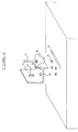
- FIG. 1 there is shown a bridge deck produced according to the invention, which comprises wooden beams 1 which can be solid or laminated glued.
- the beams are section in I and consist of several elements superimposed assembled together. They could however be rectangular.
- Beams 1 extend in the direction longitudinal of the bridge between piers and abutments, and they are braced using a set made of 2 steel tubes passing through butons wood 3, the whole being tightened by pre-stressed rods 4.
- the beams 1 are notched by notches 5, intended to receive prefabricated concrete vaults 6 which are arranged in arch shape and serve to form the space included between the beams 1.
- the outer notches 5 of the edge beams allow to support cornices prefabricated 7 which have as their object, in addition to their role decorative and protective beams, formwork vertically the concrete slab 8 of the deck as well as the overlying sidewalk 9.
- Beams 1 and prefabricated concrete blocks 6 serve as formwork for pouring the concrete slab 8, which is simply armed with a double layer of trellis welded to resist some conditions to limits, and not at the transverse moments which are eliminated thanks to the arch effect created by the concrete blocks 6.
- Connectors 12 in the form of a double angle connect the wooden beams 1 to the concrete slab 8 in opposing the sliding forces between these elements.
- a sealing layer 10 and a wearing layer 11 cover the concrete slab 8.
- the connector 12 consists of a sheet folded about 8mm thick S-shaped without upper and lower bars produced by folding or by welding two angles together.
- the amount upper 13 has dimensions of the order of 10cm x 10 cm. It is drilled with a hole 14 allowing the introduction of a round strip of about 12mm.
- a central hole 19 allows the introduction of a connector positioning and fixing tip.
- the lower upright 20 has dimensions of the order of 10cm x 3.5cm.
- the vault in prefabricated concrete blocks are made using two shore lines 22 and a key line 23 extending slightly beyond the beam in order to form the ends 24 of the apron projecting from the beams wood.
Abstract
Description
La présente invention, concernant laquelle des essais sur maquette et études ont été réalisés au Laboratoire Géomatériaux de l'ENTPE-FORMEQUIP, concerne la réalisation de structures mixtes bois-béton, notamment pour l'obtention de tabliers d'ouvrages d'art tels que des ponts. De telles structures comprennent des poutres en bois massif ou en lamellé collé à leur partie inférieure et une dalle de compression en béton connectée sur les poutres à leur partie supérieure.The present invention, which of model tests and studies were carried out at ENPEPE-FORMEQUIP Geomaterials Laboratory, concerns the realization of mixed wood-concrete structures, especially for obtaining aprons of engineering structures such as bridges. Such structures include solid wood or laminated beams glued to their part lower and a concrete compression slab connected on the beams at their upper part.
Elle s'applique en particulier, mais non exclusivement, à l'exécution de travées de petite et moyenne portées pour la circulation des piétons (passerelles) et de véhicules (ponts) et, plus généralement, pour le franchissement de brèches par des charges statiques ou dynamiques (par exemple des aqueducs) dans les portées définies ci-dessus. Elle s'applique de préférence, mais non pas limitativement, à des travées isostatiques.It applies in particular, but not exclusively for the execution of small and average ranges for pedestrian traffic (walkways) and vehicles (bridges) and, more generally, for the crossing of breaches by static or dynamic loads (e.g. aqueducts) within the scopes defined above. She preferably, but not limited to, applies to isostatic spans.
La construction de tabliers mixtes métal-béton armé pour des ponts est devenue tout à fait courante dans les pays dits "développés", en démontrant la fiabilité et le faible coût de tels ouvrages pour des portées moyennes, comparé aux ouvrages équivalents réalisés entièrement en béton armé.The construction of mixed metal-concrete decks armed for bridges has become quite common in so-called "developed" countries, demonstrating the reliability and low cost of such works for average spans, compared to equivalent works made entirely of reinforced concrete.
Toutefois ces structures métal-béton armé entraínent une très forte consommation d'acier de charpente (dans les poutres métalliques) et d'armature pour béton armé (dans la dalle supérieure). Cela constitue un obstacle important pour la construction de ponts dans les pays en voie de développement, en entraínant de lourdes dépenses de devises pour se procurer les quantités d'acier nécessaires.However these metal-reinforced concrete structures result in a very high consumption of steel from frame (in metal beams) and reinforcement for reinforced concrete (in the upper slab). That constitutes an important obstacle for the construction of bridges in developing countries, in causing heavy foreign exchange expenses to procure the necessary quantities of steel.
La présente invention a pour objet de remédier à cet inconvénient et elle propose à cet effet de substituer, aux poutres métalliques des modes de construction connus mentionnés ci-dessus, des poutres de bois de section définie en fonction des charges appliquées (pouvant varier d'une section pleine en bois massif à une section en I également en bois massif ou à une section de forme complexe en lamellé collé). Elle a également pour objet, grâce à un choix judicieux de la position de la fibre neutre de la section composite (à la frontière entre le bois et le béton), de diminuer considérablement les quantités d'acier à mettre en place pour armer la dalle de compression.The object of the present invention is to remedy to this disadvantage and it proposes for this purpose substitute, for metal beams, modes of known construction mentioned above, beams of wood of section defined according to the loads applied (may vary from solid wooden section solid in an I-section also in solid wood or a section of complex shape in glued laminate). She has also for object, thanks to a judicious choice of position of the neutral fiber of the composite section (at the border between wood and concrete), to decrease considerably the quantities of steel to be put in place to arm the compression slab.
On comprend qu'une telle substitution du bois au métal permettrait, dans les pays en voie de développement possédant des richesses naturelles en bois, d'alléger les lourdes dépenses en devises liées à l'achat d'acier et de valoriser ainsi sur place une ressource nationale qui, dans le cas contraire, serait exportée avec une plus faible valeur ajoutée.We understand that such a substitution of wood metal would, in the developing countries development with natural wealth in wood, to alleviate the heavy foreign exchange expenses linked to the purchase of steel and thus enhance on site a national resource which would otherwise be exported with lower added value.
L'association du bois et du béton constitue un procédé très ancien, bien qu'il ait buté sur la qualité de la connexion entre les poutres de bois et la dalle de compression en béton. De nombreux systèmes prévoyaient ainsi de réaliser cette connexion à l'aide de clous enfoncés dans le bois et dont la tête est noyée dans le béton. D'autres systèmes prévoyaient des plaques de connexion constituées de tôles fixées sur les deux flans de chaque poutre, à l'aide de dents de clouage horizontales obtenues par découpage et pliage de certaines parties de leur matière.The combination of wood and concrete constitutes a very old process, although it stumbled on the quality of the connection between the wooden beams and the slab of concrete compression. Many systems provided so make this connection using nails sunk into the wood and whose head is buried in the concrete. Other systems provided for plates of connection made of sheets fixed on the two blanks of each beam, using nailing teeth horizontal obtained by cutting and folding some parts of their material.
Ces systèmes connus de connexion, qui n'ont servi qu'à réaliser des planchers de bâtiment et des passerelles de faible capacité, ne sont pas conçus pour résister à tous les efforts de compression et de cisaillement générés dans les ouvrages d'art.These known connection systems, which have only used for building floors and low capacity gateways, are not designed to withstand all compression and shear generated in engineering structures.
On connait aussi, par le brevet français FR2611778 A, un plancher à collaboration bois-béton dans lequel une dalle de béton est coulée sur des poutres de bois et connectée à celles-ci par des tubes connecteurs métalliques à section circulaire qui s'encastrent chacun d'une part par enfoncement dans une gorge circulaire creusée à cet effet dans une poutre et, d'autre part, dans la dalle lors du coulage du béton. Dans ce cas aussi, ce type de connexion parait mieux adapté aux contraintes de faible et moyenne intensités. Un autre système, décrit dans le document DE673556 C et destiné aux planchers de bâtiments, comprend un agrafage des deux parties d'une structure mixte à l'aide de profilés de type en Z ou en I.We also know, by the French patent FR2611778 A, a wood-concrete collaboration floor in which a concrete slab is poured on beams of wood and connected to them by connector tubes metal with circular section which each fit on the one hand by sinking into a circular groove dug for this purpose in a beam and, on the other hand, in the slab when pouring concrete. In that case also, this type of connection seems better suited to low and medium intensity constraints. Another system, described in document DE673556 C and intended on building floors, includes stapling of two parts of a mixed structure using profiles Z or I type.
Selon la présente invention, la structure mixte bois-béton, destinée notamment à la réalisation de tabliers d'ouvrages d'art tels que des ponts, est du type qui comprend :
- des poutres de bois longitudinales reposant sur des appuis tels que des chevêtres,
- une dalle de compression en béton portée par les dites poutres, et
- des connecteurs métalliques, constitués de profilés en Z, assurant la liaison entre les poutres et la dalle de béton.
- longitudinal wooden beams resting on supports such as trimmers,
- a concrete compression slab carried by said beams, and
- metal connectors, made up of Z-sections, ensuring the connection between the beams and the concrete slab.
Avantageusement le connecteur, qui peut être constitué par une tôle pliée ou être obtenu par soudage de deux cornières standard en position tête-bêche, présente sur son aile verticale supérieure une ouverture pour le passage d'un filant longitudinal destiné à être noyé dans le béton.Advantageously the connector, which can be consisting of a folded sheet or obtained by welding two standard angles in head-to-tail position, has an opening on its upper vertical wing for the passage of a longitudinal streak intended to be drowned in concrete.
Les scellements de l'aile inférieure du connecteur dans la fente pratiquée dans le bois et des boulons ou tirefonds dans la poutre sont réalisés à l'aide d'un produit possédant les caractéristiques suivantes :
- une bonne compatibilité chimique avec le bois,
- fluidité suffisante pour imprégner les fibres de bois afin de reprendre correctement les efforts de cisaillement,
- thixotropie permettant de ne pas diffuser à l'excès le produit dans des zones où il ne serait pas utile.
- good chemical compatibility with wood,
- sufficient fluidity to impregnate the wood fibers in order to correctly take up the shearing forces,
- thixotropy allowing not to excessively diffuse the product in areas where it would not be useful.
On comprend que le connecteur selon l'invention est parfaitement adapté à l'exécution de tabliers à structure mixte bois-béton. En effet sa partie supérieure fonctionne exactement comme dans les tabliers mixtes métal/béton dans lesquels le connecteur est noyé dans la partie comprimée du béton transmettant à celui-ci une compression qui le dimensionne (il empêche également, grâce au filant traversant tous les connecteurs en file, le soulèvement de la dalle). De même sa partie inférieure enfoncée dans une fente de la poutre transmet dans les meilleures conditions possibles une compression au bois dans la limite des contraintes admissibles de celui-ci (définies par le calcul). La mobilisation des efforts est assurée par le remplissage de la fente à l'aide du produit défini plus haut.We understand that the connector according to the invention is perfectly suited to the execution of decks with a mixed wood-concrete structure. Indeed its upper part works exactly as in mixed metal / concrete decks in which the connector is embedded in the compressed part of the transmitting concrete a compression which dimensions it (it also prevents, thanks to the thread passing through all connectors in a row, lifting the slab). Of even its lower part pressed into a slot in the beam transmits in the best possible conditions wood compression within the limits of constraints admissible of it (defined by calculation). The mobilization of efforts is ensured by filling of the slit using the product defined above.
Le connecteur est fixé provisoirement sur le bois par une pointe et les efforts d'arrachement connecteur-bois sont repris par des boulons constitués d'une tige enfoncée dans un avant trou et scellée au produit défini plus haut afin de reconstituer la matière autour de la tige, et d'une tête s'opposant au soulèvement.The connector is temporarily fixed on the wood by a point and the efforts of tearing off connector-wood are taken up by constituted bolts a rod inserted in a pilot hole and sealed with product defined above in order to reconstitute the material around the stem, and a head opposing the uprising.
L'effort de cisaillement sur la section transversale de l'aile inférieure de la double cornière inversée dimensionne l'épaisseur de cette aile. Enfin l'effort de pliure sur la partie haute du connecteur dimensionne l'épaisseur de l'aile supérieure.The shear force on the section transverse of the lower wing of the double angle reversed dimensions the thickness of this wing. Finally the bending force on the upper part of the connector dimensions the thickness of the upper wing.
L'ensemble de connecteurs ainsi définis selon l'invention est en mesure de résister à tous les efforts générés par les efforts tranchants connus dans les ouvrages d'art y compris les efforts de fatigue.The set of connectors thus defined according to the invention is able to resist all efforts generated by the cutting forces known in the engineering structures including fatigue efforts.
Il est à noter que la partie inférieure du connecteur est enfoncée dans la semelle supérieure de la poutre de bois sur une part relativement faible de la hauteur totale de la dite semelle. Or, compte tenu de la position de l'axe neutre, cette zone est très faiblement tendue, ce qui signifie que les quelques fibres du bois interceptées par la partie inférieure du connecteur sont sans incidence sur la tenue de l'ensemble de la structure.Note that the lower part of the connector is pressed into the upper sole of the wooden beam on a relatively small part of the total height of said sole. However, given the position of the neutral axis, this area is very weak stretched, which means that the few fibers of the wood intercepted by the bottom of the connector are without affecting the holding of the whole structure.
Il est à noter également que les faibles dimensions du connecteur par rapport à celles de la semelle supérieure de la poutre de bois font que ce connecteur est très éloigné de l'air atmosphérique tant du côté béton que du côté bois. Cette caractéristique permet de protéger efficacement le connecteur contre les risques éventuels d'incendie ainsi que contre la corrosion, protection qui peut encore être améliorée par une galvanisation et/ou un badigeon à la résine.It should also be noted that the weak dimensions of the connector compared to those of the wooden beam upper sole make this connector is very far from atmospheric air as much on the concrete side than on the wood side. This characteristic effectively protects the connector against possible fire risks as well as against corrosion, protection which can be further improved by galvanizing and / or whitewashing with resin.
Selon une particularité de l'invention, afin de rendre la réalisation plus aisée par une main d'oeuvre non qualifiée et réduire au minimum les quantités d'acier pour béton armé, on utilise des éléments en béton préfabriqués épousant la forme d'une voûte et prenant appui sur des encoches pratiquées en rive des poutres de bois. Ces voûtes ont pour double objet :
- de constituer d'une part un coffrage perdu participant ou non pour la dalle de compression en béton située au-dessus. Cette voûte est réalisée à l'aide de trois files de parpaings (deux files de rive et une file de clef) dont la flèche et l'épaisseur sont déterminées par la nécessité d'être entièrement comprimée sous l'effet du béton liquide de la dalle de compression.
- de transmettre directement, grâce à l'effet de voûte créé, les efforts des charges statiques et dynamiques de la chaussée aux poutres de bois et d'éviter ainsi la création de moments de flexion transversaux importants qui auraient imposé l'augmentation sensible des quantités d'acier dans la dalle, réduisant d'autant l'intérêt du procédé.
- to constitute on the one hand a lost formwork participating or not for the concrete compression slab situated above. This vault is made using three rows of concrete blocks (two shore rows and a row of keys) whose deflection and thickness are determined by the need to be fully compressed under the effect of the liquid concrete of the compression slab.
- to transmit directly, thanks to the vault effect created, the forces of static and dynamic loads from the roadway to the wooden beams and thus avoid the creation of significant transverse bending moments which would have required the appreciable increase in the quantities of steel in the slab, thereby reducing the interest of the process.
L'ensemble des éléments à mettre en place est suffisamment léger pour être manipulé manuellement ou à l'aide de palans.All the elements to be put in place are light enough to be handled manually or using hoists.
Les poutres de bois longitudinales sont normalement entretoisées selon un rythme défini par le calcul. Ces entretoises sont en principe constituées d'un tube en acier reprenant les cisaillements traversant un élément de béton en bois qui reprend les compressions et d'une tige de serrage en acier FE 500 ou acier dur - (suivant les efforts concernés) - qui reprend les tractions. Les poutres bois reposent sur des chevêtres constituant des appuis.The longitudinal wooden beams are normally braced at a rate defined by the calculation. These spacers are in principle made up a steel tube taking up the shears crossing a wooden concrete element which takes up the compressions and a FE 500 steel clamping rod or hard steel - (depending on the efforts concerned) - which resumes pull-ups. The wooden beams rest on headers constituting supports.
Enfin pour rendre l'exécution plus aisée encore, des éléments préfabriqués posés en rive du tablier sur une encoche latérale des poutres de rive servent à la fois de coffrage perdu vertical pour la dalle de compression et le trottoir sus-jacent, mais également de protection contre l'écoulement des eaux le long des poutres de rive et de parement décoratif.Finally to make execution easier again, prefabricated elements placed on the bank of the deck on a side notch of the edge beams both serve as vertical lost formwork for the compression slab and the overlying sidewalk but also of protection against the flow of water the along the edge beams and decorative facing.
L'invention telle que définie peut être mise en oeuvre à la fois dans les pays en voie de développement pour son utilisation maximale de ressources locales et la simplicité de son exécution, et dans les pays industriels qui désirent développer la filière bois à des coûts raisonnables grâce à une faible consommation de main d'oeuvre sur le chantier proprement dit.The invention as defined can be implemented implemented both in developing countries development for its maximum use of local resources and the simplicity of its execution, and in industrial countries that wish to develop the wood industry at reasonable costs thanks to low consumption of labor on site properly said.
Pour bien faire comprendre l'invention on en
décrira ci-après, à titre d'exemple sans caractère
limitatif, une forme d'exécution préférée en référence
au dessin schématique annexé dans lequel :
En référence à la figure 1 on a représenté un tablier de pont réalisé selon l'invention, qui comporte des poutres en bois 1 pouvant être massives ou lamellées collées. Dans l'exemple représenté, les poutres sont de section en I et sont constituées de plusieurs éléments superposés assemblés entre eux. Elles pourraient toutefois être de forme rectangulaire.Referring to Figure 1 there is shown a bridge deck produced according to the invention, which comprises wooden beams 1 which can be solid or laminated glued. In the example shown, the beams are section in I and consist of several elements superimposed assembled together. They could however be rectangular.
Les poutres 1 s'étendent dans le sens longitudinal du pont entre appuis des piles et culées, et elles sont entretoisées à l'aide d'un ensemble constitué de tubes d'acier 2 traversant des butons en bois 3, le tout étant serré par des tiges précontraintes 4 .Beams 1 extend in the direction longitudinal of the bridge between piers and abutments, and they are braced using a set made of 2 steel tubes passing through butons wood 3, the whole being tightened by pre-stressed rods 4.
A leur partie supérieure, les poutres 1 sont
entaillées par des encoches 5, destinées à recevoir des
voutains 6 en béton préfabriqué qui sont disposés en
forme de voûte et servent à coffrer l'espace compris
entre les poutres 1. Les encoches extérieures 5 des
poutres de rive permettent d'appuyer des corniches
préfabriquées 7 qui ont pour objet, outre leur rôle
décoratif et de protection des poutres, de coffrer
verticalement la dalle en béton 8 du tablier ainsi que
le trottoir susjacent 9.At their upper part, the beams 1 are
notched by notches 5, intended to receive
prefabricated concrete vaults 6 which are arranged in
arch shape and serve to form the space included
between the beams 1. The outer notches 5 of the
edge beams allow to support cornices
prefabricated 7 which have as their object, in addition to their role
decorative and protective beams, formwork
vertically the
Les poutres 1 et les parpaings préfabriqués 6
servent de coffrage pour couler la dalle en béton 8, qui
est simplement armée d'une double nappe de treillis
soudé destinée à résister à quelques conditions aux
limites, et non aux moments transversaux qui sont
éliminés grâce à l'effet de voûte créé par les parpaings
6.Beams 1 and prefabricated concrete blocks 6
serve as formwork for pouring the
Des connecteurs 12 en forme de double cornière
relient les poutres de bois 1 à la dalle de béton 8 en
s'opposant aux efforts de glissement entre ces éléments.
Une couche d'étanchéité 10 et une couche de roulement 11
viennent recouvrir la dalle de béton 8.Connectors 12 in the form of a double angle
connect the wooden beams 1 to the
Comme on le voit plus particulièrement à la
figure 2, le connecteur 12 est constitué d'une tôle
pliée d'environ 8mm d'épaisseur en forme de S sans
barres supérieure et inférieure réalisée par pliure ou
par soudure de deux cornières entre elles. Le montant
supérieur 13 a des dimensions de l'ordre de
10cm x 10 cm. Il est percé d'un trou 14 permettant
l'introduction d'un rond filant d'environ 12mm.As can be seen more particularly in the
Figure 2, the connector 12 consists of a sheet
folded about 8mm thick S-shaped without
upper and lower bars produced by folding or
by welding two angles together. The amount
upper 13 has dimensions of the order of
10cm x 10 cm. It is drilled with a
La partie horizontale 15, qui dans la
structure est fixée sur la face supérieure de la poutre
bois, a des dimensions de l'ordre de 10cm x 10 cm. Elle
est percée de quatre trous principaux 16 destinés au
passage de tiges 17 de fixation du connecteur sur la
poutre bois. Les tiges sont scellées à l'aide d'un
produit de scellement dans des avant-trous 18 ménagés
dans les poutres bois. Elles sont munies d'une tête
s'opposant aux efforts d'arrachement du connecteur.The
Un trou central 19 permet l'introduction d'une
pointe de positionnement et de fixation du connecteur.A
Le montant vertical inférieur 20 a des
dimensions de l'ordre de 10cm x 3,5cm.The
Il est introduit dans une fente 21 réalisée
dans le bois à la défonceuse et scellée à l'aide d'un
produit de scellement.It is inserted into a
Comme on le voit à la figure 3, la voûte en
parpaings préfabriqués est réalisée à l'aide de deux
files de rive 22 et une file de clef 23 s'étendant
légèrement au delà de la poutre afin de coffrer les
abouts 24 du tablier en débord par rapport aux poutres
bois.As seen in Figure 3, the vault in
prefabricated concrete blocks are made using two
On comprendra que la description ci-dessus a été donnée à simple titre d'exemple, sans caractère limitatif, et que des adjonctions ou des modifications constructives pourraient y être apportées.It will be understood that the above description has was given as an example, without character limiting, and that additions or modifications could be made.
On comprendra en particulier qu'on a décrit l'invention comme s'appliquant à la réalisation d'un tablier de pont, mais qu'elle pourrait tout aussi bien s'appliquer à la réalisation de planchers de bâtiments.We will understand in particular that we have described the invention as applying to the realization of a bridge deck but that she might as well apply to the realization of building floors.
Claims (10)
- Composite wood - concrete structure aimed at bridges construction including:characterized in the so called connecting devices (12) appearing in the shape of a double inverted angle whose top flange (13) is embedded in the compression slab (8), whose bottom flange (20) is fixed inside a slot (21) grooved in the top sole of the beam (1) and whose intermediate horizontal part (15) is fitted to the beam (1).longitudinal wood beams (1) lying on bearings.compression concrete slab (8) supported by the above mentionned beams (1), andmetallic connecting devices (12) securing the connection between the so called beams (1) and the concrete slab (8),
- Composite wood - concrete structure according to claim 1 characterized in the fitting of the horizontal part (15) of the connecting device (12) to the beam (1) being carried out by rods (17) placed in holes (18) drilled in the beam (1).
- Composite wood - concrete structure according to claim 2 characterized by the sealing of the bottom flange (20) in the slot (21) and of the rods (17) in the holes (18), this sealing being achieved by means of a chemical produce with the following characteristics:good chemical compatibility with timberSufficient fluidity insuring a proper impregnation of timber fibres in order to correctly resist shear stressesgood thixotropic quality so as to prevent the produce to spread in areas where it would be of no use.
- Composite wood - concrete structure according to any of the Claims 1 to 3, characterized in the top flange (13) of the connecting device (12) being connected to the concrete in order to resist the uprising of the concrete slab (8) using-by instance - an opening (14) through which a longitudinal renforcement bar can be pulled and eventually embedded in the concrete slab (8).
- Composite wood - concrete structure according to any of the claims 1 to 4, characterized in the connecting device (12) being made of bended steel sheet.
- Composite wood - concrete structure according to any of the claims 1 to 4, characterized in the connecting device (12) being made of two welded inverted angles.
- Composite wood - concrete structure according to any of the previous claims, characterized by the placing between beams (1) of vaults made of precast concrete elements (6) constituting a lost formwork to the concrete slab (8) and transferring to beams (1) the efforts coming from the static and dynamic road loads thanks to a clever combination between the thickness of the precast elements (6) and the rise of the vaults enabling a consistant reduction of steel reinforcement in the concrete slab.
- Composite wood - concrete structure according to claim 7, characterized in the grooving of the top sole of beams (1) on each side in order to fit (5) in the so called precast elements (6) constituting the vaults.
- Composite wood - concrete structure according to claim 8, characterized in that external grooves (5) in side beams (1) fit in precast edge beams (7).
- Composite wood - concrete structure according to any of the claims 7 to 9, characterized in that the vaults constituted of precast elements (6) are arranged in two side files and one key file stretching slightly further beyond the beams (1) length in order to form the ends of the deck slab (24) which protrudes beyond the timber beams (1).
Applications Claiming Priority (2)
| Application Number | Priority Date | Filing Date | Title |
|---|---|---|---|
| FR9414975A FR2727993A1 (en) | 1994-12-13 | 1994-12-13 | MIXED WOOD-CONCRETE STRUCTURE INTENDED IN PARTICULAR TO THE PRODUCTION OF APARTMENTS OF ART WORKS |
| FR9414975 | 1994-12-13 |
Publications (2)
| Publication Number | Publication Date |
|---|---|
| EP0717149A1 EP0717149A1 (en) | 1996-06-19 |
| EP0717149B1 true EP0717149B1 (en) | 2000-08-16 |
Family
ID=9469750
Family Applications (1)
| Application Number | Title | Priority Date | Filing Date |
|---|---|---|---|
| EP95402782A Expired - Lifetime EP0717149B1 (en) | 1994-12-13 | 1995-12-12 | Mixed structure of wood-concrete, especially for the construction of bridge decks |
Country Status (4)
| Country | Link |
|---|---|
| EP (1) | EP0717149B1 (en) |
| AT (1) | ATE195563T1 (en) |
| DE (1) | DE69518396T2 (en) |
| FR (1) | FR2727993A1 (en) |
Families Citing this family (7)
| Publication number | Priority date | Publication date | Assignee | Title |
|---|---|---|---|---|
| US5809722A (en) * | 1997-02-06 | 1998-09-22 | Keith M. Wright | Girder supported reinforced concrete slab building structures with shearing connectors, and methods of constructing the building structures and connectors |
| DE19808208A1 (en) * | 1998-02-27 | 1999-09-02 | Fischer Artur Werke Gmbh | Connection element for connecting wood and concrete |
| FR2843978B1 (en) * | 2002-08-28 | 2005-03-11 | Conseil Service Investissement | METHOD FOR MAKING A CROSSING WORK COMPRISING AN INTERNAL CONDUIT |
| EP2557244A1 (en) * | 2011-08-09 | 2013-02-13 | MiTek Holdings, Inc. | A bracket for connecting timber to concrete |
| ES2511992B1 (en) * | 2013-04-08 | 2015-07-28 | Carlos González Bravo | Connector for connection of mixed wood-concrete structures |
| DE102016125008A1 (en) * | 2016-12-20 | 2018-06-21 | Fischer Italia S.R.L. | Wood-concrete connector and mounting arrangement |
| CN111549912A (en) * | 2020-06-04 | 2020-08-18 | 郑州大学 | Wood-concrete connection structure using channel steel and self-tapping screws |
Family Cites Families (5)
| Publication number | Priority date | Publication date | Assignee | Title |
|---|---|---|---|---|
| GB415844A (en) * | 1933-04-13 | 1934-09-06 | Francis Albert Leon Wellard | Improvements in the construction of arches for bridges, culverts and similar purposes |
| DE673556C (en) * | 1936-09-20 | 1939-03-24 | Otto Schaub | Composite ceiling made of wooden ribs and concrete slab |
| FR2611778B1 (en) * | 1987-02-26 | 1992-04-24 | Paris Ouest Entreprise | WOOD-CONCRETE COLLABORATION FLOOR |
| CH687397A5 (en) * | 1992-11-14 | 1996-11-29 | Bettex Fabienne | Wood-concrete composite floor. |
| FR2702236B1 (en) * | 1993-03-03 | 1995-08-04 | Gauthier Daniel | WOOD-CONCRETE COMPOSITE CONSTRUCTION ELEMENT. |
-
1994
- 1994-12-13 FR FR9414975A patent/FR2727993A1/en active Granted
-
1995
- 1995-12-12 EP EP95402782A patent/EP0717149B1/en not_active Expired - Lifetime
- 1995-12-12 AT AT95402782T patent/ATE195563T1/en not_active IP Right Cessation
- 1995-12-12 DE DE69518396T patent/DE69518396T2/en not_active Expired - Fee Related
Also Published As
| Publication number | Publication date |
|---|---|
| DE69518396T2 (en) | 2001-03-29 |
| EP0717149A1 (en) | 1996-06-19 |
| DE69518396D1 (en) | 2000-09-21 |
| FR2727993B1 (en) | 1997-02-07 |
| FR2727993A1 (en) | 1996-06-14 |
| ATE195563T1 (en) | 2000-09-15 |
Similar Documents
| Publication | Publication Date | Title |
|---|---|---|
| CA1322668C (en) | Concrete wood floor | |
| EP0717149B1 (en) | Mixed structure of wood-concrete, especially for the construction of bridge decks | |
| JP5464350B2 (en) | Wooden bridge using prestressed wood deck | |
| EP1045089B1 (en) | Masonry structure and associated reinforcement method | |
| EP1149213B1 (en) | Building slab, assembly of same and use for producing structures capable of supporting heavy loads | |
| EP0369914A1 (en) | Method for joining a matrix material to a functional support, and devices manufactured according to this method | |
| EP0985071A1 (en) | Building framework | |
| FR2795438A1 (en) | STRUCTURE OF A CONCRETE-STEEL MIXED BRIDGE OR GATEWAY, PARTICULARLY A MIXED TWO-GATE APRON BRIDGE | |
| FR3066514B1 (en) | LOST INSULATED FORMWORK AND ASSOCIATED METHOD FOR MAKING A WALL. | |
| FR2573848A1 (en) | STABLE STRUCTURE COMPRISING TUBULAR ELEMENTS AND POST-TENSILE CABLES OR OTHER VOLTAGE DEVICES | |
| EP1452670B1 (en) | Method for reinforcing a building element and building element | |
| FR2817575A1 (en) | Reinforcing procedure for masonry structure such as arch or lintel applying upper layers of materials accepting traction and compression forces | |
| FR2564507A1 (en) | Upright for a beam having a hollowed-out web, beams and buildings including such uprights | |
| WO1990011417A1 (en) | Structure, in particular made of wood and process for its production | |
| FR2865490A1 (en) | Building structure e.g. stone archway, reinforcing process for e.g. monument, involves adding reinforcement units on upper part of building structure, where units have mesh nets with synthetic fibers fixed to structure via fixation points | |
| FR2736372A1 (en) | BEAM STRUCTURE AND ARTICLES USING THE SAME | |
| Ekeberg et al. | Flisa Bridge, Norway—a record-breaking timber bridge | |
| FR2500038A1 (en) | Prefabricated beam supporting slab walls of buildings - has H-shaped cross=section with slab bearing on inner face in which is bedded fixing rail | |
| EP1045091B1 (en) | Construction element reinforcement method | |
| FR2704886A1 (en) | Structural element, especially one made of timber | |
| FR2459343A1 (en) | Industrial building framework for cyclone prone countries - has I=section concrete beams with hooked fixings holding on roof so superstructure mass ballasts construction | |
| GB2399829A (en) | Load bearing span | |
| WO2002092929A1 (en) | Building device, in particular of the dwelling-type | |
| FR2567943A1 (en) | Composite construction element, method of manufacturing an element and equipment for implementing the said method | |
| FR2637313A1 (en) | STRUCTURE OF BUILDINGS FOR AGRICULTURAL HANGARS, ESPECIALLY |
Legal Events
| Date | Code | Title | Description |
|---|---|---|---|
| PUAI | Public reference made under article 153(3) epc to a published international application that has entered the european phase |
Free format text: ORIGINAL CODE: 0009012 |
|
| AK | Designated contracting states |
Kind code of ref document: A1 Designated state(s): AT BE CH DE LI NL |
|
| 17P | Request for examination filed |
Effective date: 19961217 |
|
| GRAG | Despatch of communication of intention to grant |
Free format text: ORIGINAL CODE: EPIDOS AGRA |
|
| 17Q | First examination report despatched |
Effective date: 19990723 |
|
| GRAG | Despatch of communication of intention to grant |
Free format text: ORIGINAL CODE: EPIDOS AGRA |
|
| GRAG | Despatch of communication of intention to grant |
Free format text: ORIGINAL CODE: EPIDOS AGRA |
|
| GRAH | Despatch of communication of intention to grant a patent |
Free format text: ORIGINAL CODE: EPIDOS IGRA |
|
| GRAH | Despatch of communication of intention to grant a patent |
Free format text: ORIGINAL CODE: EPIDOS IGRA |
|
| GRAA | (expected) grant |
Free format text: ORIGINAL CODE: 0009210 |
|
| AK | Designated contracting states |
Kind code of ref document: B1 Designated state(s): AT BE CH DE LI NL |
|
| PG25 | Lapsed in a contracting state [announced via postgrant information from national office to epo] |
Ref country code: NL Free format text: LAPSE BECAUSE OF FAILURE TO SUBMIT A TRANSLATION OF THE DESCRIPTION OR TO PAY THE FEE WITHIN THE PRESCRIBED TIME-LIMIT Effective date: 20000816 Ref country code: AT Free format text: LAPSE BECAUSE OF FAILURE TO SUBMIT A TRANSLATION OF THE DESCRIPTION OR TO PAY THE FEE WITHIN THE PRESCRIBED TIME-LIMIT Effective date: 20000816 |
|
| REF | Corresponds to: |
Ref document number: 195563 Country of ref document: AT Date of ref document: 20000915 Kind code of ref document: T |
|
| REG | Reference to a national code |
Ref country code: CH Ref legal event code: EP |
|
| REF | Corresponds to: |
Ref document number: 69518396 Country of ref document: DE Date of ref document: 20000921 |
|
| PGFP | Annual fee paid to national office [announced via postgrant information from national office to epo] |
Ref country code: DE Payment date: 20001114 Year of fee payment: 6 |
|
| PGFP | Annual fee paid to national office [announced via postgrant information from national office to epo] |
Ref country code: BE Payment date: 20001130 Year of fee payment: 6 |
|
| PG25 | Lapsed in a contracting state [announced via postgrant information from national office to epo] |
Ref country code: LI Free format text: LAPSE BECAUSE OF NON-PAYMENT OF DUE FEES Effective date: 20001231 Ref country code: CH Free format text: LAPSE BECAUSE OF NON-PAYMENT OF DUE FEES Effective date: 20001231 |
|
| PLBE | No opposition filed within time limit |
Free format text: ORIGINAL CODE: 0009261 |
|
| STAA | Information on the status of an ep patent application or granted ep patent |
Free format text: STATUS: NO OPPOSITION FILED WITHIN TIME LIMIT |
|
| 26N | No opposition filed | ||
| REG | Reference to a national code |
Ref country code: CH Ref legal event code: PL |
|
| PG25 | Lapsed in a contracting state [announced via postgrant information from national office to epo] |
Ref country code: BE Free format text: LAPSE BECAUSE OF NON-PAYMENT OF DUE FEES Effective date: 20011231 |
|
| BERE | Be: lapsed |
Owner name: SOPRESE S.A.R.L. Effective date: 20011231 |
|
| PG25 | Lapsed in a contracting state [announced via postgrant information from national office to epo] |
Ref country code: DE Free format text: LAPSE BECAUSE OF NON-PAYMENT OF DUE FEES Effective date: 20020702 |