EP0716950B1 - Fixation amovible du piètement d'un siège de véhicule sur un plancher - Google Patents
Fixation amovible du piètement d'un siège de véhicule sur un plancher Download PDFInfo
- Publication number
- EP0716950B1 EP0716950B1 EP19950402495 EP95402495A EP0716950B1 EP 0716950 B1 EP0716950 B1 EP 0716950B1 EP 19950402495 EP19950402495 EP 19950402495 EP 95402495 A EP95402495 A EP 95402495A EP 0716950 B1 EP0716950 B1 EP 0716950B1
- Authority
- EP
- European Patent Office
- Prior art keywords
- bolt
- seat
- order
- cam
- ball
- Prior art date
- Legal status (The legal status is an assumption and is not a legal conclusion. Google has not performed a legal analysis and makes no representation as to the accuracy of the status listed.)
- Expired - Lifetime
Links
- 230000000717 retained effect Effects 0.000 claims description 3
- 230000001012 protector Effects 0.000 description 5
- OQCFWECOQNPQCG-UHFFFAOYSA-N 1,3,4,8-tetrahydropyrimido[4,5-c]oxazin-7-one Chemical compound C1CONC2=C1C=NC(=O)N2 OQCFWECOQNPQCG-UHFFFAOYSA-N 0.000 description 4
- 238000004873 anchoring Methods 0.000 description 4
- 238000000034 method Methods 0.000 description 3
- 210000004027 cell Anatomy 0.000 description 1
- 230000006835 compression Effects 0.000 description 1
- 238000007906 compression Methods 0.000 description 1
- 239000000470 constituent Substances 0.000 description 1
- 238000011109 contamination Methods 0.000 description 1
- 230000008094 contradictory effect Effects 0.000 description 1
- 238000002788 crimping Methods 0.000 description 1
- 230000003111 delayed effect Effects 0.000 description 1
- 238000006073 displacement reaction Methods 0.000 description 1
- 230000000694 effects Effects 0.000 description 1
- 230000003100 immobilizing effect Effects 0.000 description 1
- 238000004519 manufacturing process Methods 0.000 description 1
- 239000000463 material Substances 0.000 description 1
- 239000002184 metal Substances 0.000 description 1
- 238000005192 partition Methods 0.000 description 1
- 230000002093 peripheral effect Effects 0.000 description 1
- 230000035939 shock Effects 0.000 description 1
Images



Classifications
-
- E—FIXED CONSTRUCTIONS
- E05—LOCKS; KEYS; WINDOW OR DOOR FITTINGS; SAFES
- E05B—LOCKS; ACCESSORIES THEREFOR; HANDCUFFS
- E05B63/00—Locks or fastenings with special structural characteristics
- E05B63/12—Locks or fastenings with special structural characteristics with means carried by the bolt for interlocking with the keeper
- E05B63/121—Locks or fastenings with special structural characteristics with means carried by the bolt for interlocking with the keeper using balls or the like cooperating with notches
-
- B—PERFORMING OPERATIONS; TRANSPORTING
- B60—VEHICLES IN GENERAL
- B60N—SEATS SPECIALLY ADAPTED FOR VEHICLES; VEHICLE PASSENGER ACCOMMODATION NOT OTHERWISE PROVIDED FOR
- B60N2/00—Seats specially adapted for vehicles; Arrangement or mounting of seats in vehicles
- B60N2/005—Arrangement or mounting of seats in vehicles, e.g. dismountable auxiliary seats
- B60N2/015—Attaching seats directly to vehicle chassis
- B60N2/01508—Attaching seats directly to vehicle chassis using quick release attachments
- B60N2/01516—Attaching seats directly to vehicle chassis using quick release attachments with locking mechanisms
- B60N2/01525—Attaching seats directly to vehicle chassis using quick release attachments with locking mechanisms with locking elements expanding inside or under the vehicle floor or rail
- B60N2/01533—Attaching seats directly to vehicle chassis using quick release attachments with locking mechanisms with locking elements expanding inside or under the vehicle floor or rail using balls interlocking with notches
-
- Y—GENERAL TAGGING OF NEW TECHNOLOGICAL DEVELOPMENTS; GENERAL TAGGING OF CROSS-SECTIONAL TECHNOLOGIES SPANNING OVER SEVERAL SECTIONS OF THE IPC; TECHNICAL SUBJECTS COVERED BY FORMER USPC CROSS-REFERENCE ART COLLECTIONS [XRACs] AND DIGESTS
- Y10—TECHNICAL SUBJECTS COVERED BY FORMER USPC
- Y10T—TECHNICAL SUBJECTS COVERED BY FORMER US CLASSIFICATION
- Y10T70/00—Locks
- Y10T70/50—Special application
- Y10T70/5996—For seats
Definitions
- the present invention relates to devices for attachment or anchor to detachably hold and safe, an object on a surface, such as for example a land vehicle seat on the floor or ground of this one.
- CA-A-1 181 112 describes a pin fixing device with expandable ball with programmed delayed opening.
- Seats of this type should, for example, be able to be busy, able to fully deploy in a berth, in a relaxation or relax chair, in a seat normal said to be driving or driving, or partially deploying in tablets. They should also be able to retract to partially fold or fold totally compactly and relatively little bulky in view of their retraction into the vehicle or their removal from the latter; they are then unfit to be busy.
- Documents FR-A-2 689 739 and FR-A-2 705 289 describe seats of this type.
- the seat conceals under its occupant or even is entrained by the latter in the event that the seat belt which team the seat is no longer directly anchored in two or three points of the structure or hull of the vehicle, but at otherwise this belt is integral with the seat and is somehow "embedded” on it, the different seat belt anchor points being established directly on the seat itself.
- efforts to absorb and / or transmit in the event of an impact are mainly located especially in the area the base of the seat and the floor of the vehicle as well than at their junction.
- the object of the invention is to produce a device pin type retractable ball pin which is suitable in all cases where it is necessary to quickly lock and unlock two parts relative to each other under safe conditions optimum.
- the subject of the invention is a device (as described in the first independent claim) for the removable fixing, on a floor, of the base of a multiple configuration seat with extended position where it is fit to be occupied and with a retracted position where he is unfit to be busy and where one goes from one of these positions to the other by tilting according to a direction given.
- This system consists in particular, on the one hand, a striker which is associated with the floor and which has two opposite support and locking faces pierced with an opening with free passage bordered by a contact area on the locking face and, on the other hand, a chest carrying a bolt made of elongated hollow locking body with a cavity cylindrical guide whose axis is orthogonal to this direction given and with a tip, and with at least one channel piercing the body to lead into the cavity and with one open end, and at least one ball housed in the canal to be held mobile between a first position to partially project outside of the body in order to be able to meet the contact area to lock the latch on the strike when its end is engaged in the passage and a second retracted position in the body in order to separate from the contact area of way to unlock the latch bolt, a needle movable in the cavity between a position active where it protrudes the ball and a position inactive where it allows the ball to retract, with a barrel cylindrical, with an inner end made of trunc
- a device known like this East characterized, according to the invention, in that the control comprises a lever which has an operating handle and a hinge associated with the trunk to allow it to turn according to a axis parallel to the given direction between a position of unlocking and a locking position and that carries the link in order to be able to move the needle between its two positions, and in that it includes a safety device coupled to the lever and intended to cooperate with the base to prevent the tilting of the seat in deployed position until the bolt is locked on the keeper.
- the invention also relates to the application of a device of the type indicated previously at a seat land motor vehicle for its removable mounting on the floor of the latter.
- the device according to the invention is described about its specific application to a land vehicle seat including configuration multiple with a deployed position where it is able to be occupied and with a retracted position where it is unfit to be busy, and where one goes from one to the other of these two positions by tilting according to a direction given. It is clear that the invention is not limited to this particular application.
- Such a seat includes a base P with at least a foot intended to rest directly or not on a ground S or floor on which it is to be fixed in a way removable.
- a seat usually rests on the floor using a base with a junction articulated which allows tilting in one direction data ⁇ , most often transverse to the longitudinal axis traditional vehicle.
- Such an articulated junction is obtained in any conventional way for example at using pivots and bearings or the like.
- a ball pin device expandable retractable comprises, essentially, a keeper 10, a trunk 20, a bolt 30, a command 40, a safety 50 and, preferably, a protector 60.
- Keep 10 for example made of a plate in suitable metal sheet, is intended to be fixed on the floor P of a vehicle, in particular between two partitions of the last.
- the keeper 10 comprises two opposite faces, a support face 101 and a locking face 102.
- the strike 10 is pierced right through, from one of the facing each other, with an opening 11 with a passage 111 free and a contact area 112 for example set back for the reasons that will be understood later.
- This contact area 112 presents itself for example in the manner depression or annular chamfer or the like.
- Chest 20 which is for example intended to be associated with and to cooperate with the base P to define the tilting axis ⁇ using the articulated junction, carries the rest of the device according to the invention.
- Chest 20 consists for example of two lateral flanges 21 practically symmetrical about a perpendicular plane to management ⁇ .
- the bolt 30 essentially comprises a body 31, at least one ball 32, one needle 33 and means for guide 34 of the needle in the body.
- the body 31 is elongated and hollow, and has a guide cavity 310, for example cylindrical, a end piece 311 preferably closed, and one end 313 opened.
- the body 31 is provided with at least one channel 312 the piercing to open into the cavity 310.
- At least one ball 32 is housed in each channel to be held mobile between a first position to partially protrude outside the body in order to ability to meet contact area 112 so that lock the bolt 30 on the striker 10, and a second retracted position in the body in order to separate from the contact zone 112 so as to unlock the bolt 30 of the keeper 10.
- the balls are retained in the channels for example by crimping or a similar technique.
- the needle 33 is housed mobile in translation in the cavity 310 enters an active position in which it is able to protrude the balls in their first position and keep them in that position, and a inactive position for which the balls can take their second retracted position.
- the needle 33 includes a bole 331 for example cylindrical, an inner end 332 consisting of a trunk of cone 3321 converging towards a pilot 3322 and also an external end 333 whose role will appear later.
- the guide means 34 include by example of the 342 shoulders on the barrel of the needle, which each cooperate with corresponding scopes 343 of the cavity.
- a seal 341 for example an O-ring, seals.
- the control 40 is carried by the trunk 20 and is connected by a link 41 to the outer end 333 of the needle 33 to move the needle 33 in the body 31.
- the command 40 is presented in the manner of a lever 42 which is equipped with a handle 421 for maneuvering and a joint 422 associated with the trunk 20 for him allow turning by describing a centered arc on an axis parallel to the given direction ⁇ , between a unlocking position and a locking position, and which carries the link 41 in order to be able to move the needle 33 between its two corresponding positions.
- connection 41 is preferably provided with clearance.
- the connection 41 comprises for example a dowel 410 carried by the outer end 333 of the needle 33 in which it is engaged through a transverse hole 413, and at least one light 412 formed in the lever in order to be able to move there for example with play. play is made either in the lever or the needle or in both, for kinematic reasons since the needle moves in a translation and the lever moves in an arc.
- the articulation 422 of the lever 42 on the flanges 21 of the trunk 20 which allows it to move along an axis parallel to the given direction ⁇ , is obtained from any classic way appropriate for example using pivots and bearings.
- Safety 50 is coupled to lever 42 and cooperates with base P to prevent the seat from tilting in the deployed position until the bolt is locked on the keeper.
- Security 50 essentially comprises a cam 51 carried by the lever 42, a cam follower 52 cooperating with cam 51 and movably mounted on the trunk 20 so that it can move parallel to the given direction ⁇ , a mobile stop 53 associated with the cam follower 52 of which it is integral with displacements so to move between an inoperative recessed position and an operating projecting position, as well as a stop 54 carried by the base and able to meet the retainer in operating surface position.
- the cam 51 is in the form of a ramp, single or multiple, whose active surface is directed according to the given direction ⁇ .
- the cam follower 52 presents itself for example in the manner of a rod which is mounted transversely orthogonally to the given direction ⁇ , like we will understand it later.
- Stop 53 includes a finger 531 slidably mounted parallel to the direction given ⁇ in the trunk 20 for example using housings 5311 formed in each of the flanges 21 of the trunk 20, an elastic stress 532 such as for example a coil spring with helical turns working at the compression and acting on finger 531 to maintain contact cam 51 and cam follower 52 and to tend to place the stopper 53 in the operative projecting position, as well as a extension 533 able to be placed on the trajectory described by the stop 54 when the base P passes from to each other from its two positions, to hinder it and prevent tilting in the deployed position when the bolt is not locked on the strike.
- an elastic stress 532 such as for example a coil spring with helical turns working at the compression and acting on finger 531 to maintain contact cam 51 and cam follower 52 and to tend to place the stopper 53 in the operative projecting position
- a extension 533 able to be placed on the trajectory described by the stop 54 when the base P passes from to each other from its two positions, to hinder it and prevent tilting in
- the protector 60 essentially comprises a sleeve 61 slidingly mounted on the outside of the body 31 of the bolt 30, a spring 62, a stroke limiter 63 defining the amplitude of the travel of the sleeve 61 relative to the body 31.
- This stroke limiter 63 is made for example of shoulders 631 inside the socket 61 and an elastic ring 632 such as a "CIRCLIPS" engaged in a peripheral groove 633 of the body 31 of the bolt 30.
- the protector also includes a spring cover 64 with a rim 641 and a cover 65 with a rim 651.
- the spring 62 bears against each of the edges of the spring cover and the hood which are capable of sliding one into the other, so as to push the sleeve back into one position in which it normally covers the channels and thus prevents the balls from occupying their first position projecting.
- All the components of a device according to the invention are made using conventional materials, preferably metallic, which are shaped and worked according to traditional techniques.
Landscapes
- Engineering & Computer Science (AREA)
- Aviation & Aerospace Engineering (AREA)
- Transportation (AREA)
- Mechanical Engineering (AREA)
- Structural Engineering (AREA)
- Seats For Vehicles (AREA)
Description
- d'une rapidité de verrouillage et de déverrouillage;
- d'encliquetage et de déverrouillage manuels par action sur une commande,
- du signalement à l'aide de témoins de sûreté d'un mauvais encliquetage et/ou ancrage au plancher interdisant l'usage du siège,
- ainsi que de la protection de ses constituants essentiels notamment contre les chocs et les souillures.
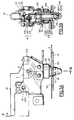
- sur la figure 1 la vue A est une représentation perspective schématique éclatée d'un mode de réalisation de l'invention dans son application à un siège de véhicule automobile terrestre, et la vue B est une représentation perspective schématique avec coupes locales d'une partie assemblée de ce mode de réalisation.
- les vues A et B de la figure 2 sont respectivement des vues en élévation et de face partiellement en coupe selon la ligne II-II, du dispositif selon l'invention de la figure 1, en position déverrouillée avant ancrage;
- les vues A et B de la figure 3 sont des vues analogues à celles de la Fig.2 où le dispositif selon l'invention est en position verrouillée ancrage fait, et
- la figure 4 est une vue perspective partielle illustrant le dispositif selon l'invention dans une position qui correspond à celle où il est représenté sur les vues de la Fig.2.
Claims (11)
- Dispositif pour la fixation amovible sur un plancher (S), du piètement (P) d'un siège à configuration multiple avec une position déployée où il est apte à être occupé et une position rétractée où il est inapte à être occupé et où l'on passe de l'une à l'autre de ces deux positions par basculement selon une direction (▵) donnée, ce dispositif étant constitué notamment, d'une part, d'une gâche (10) qui est associée au plancher (S) et qui présente deux faces (101, 102) d'appui et de verrouillage opposées transpercées d'une ouverture (11) avec un passage (111) libre bordé d'une zone (112) de contact sur la face de verrouillage (102) et, d'autre part, d'un coffre (20) qui porte un pêne (30) fait d'un corps (31) de verrouillage longiligne creux avec une cavité (310) cylindrique de guidage dont l'axe est orthogonal à cette direction (▵) et avec un embout (311), et avec au moins un canal (312) transperçant ce corps (31) pour déboucher dans la cavité (310) et avec une extrémité (313) ouverte, d'au moins une bille (32) logée dans le canal (312) pour y être retenue mobile entre une première position pour saillir partiellement à l'extérieur du corps (31) afin de pouvoir rencontrer la zone de contact (112) pour verrouiller le pêne (30) sur la gâche (10) quand son embout (311) est engagé dans le passage (111) et une seconde position escamotée dans le corps (31) afin de se séparer de la zone de contact (112) de manière à déverrouiller le pêne (30) de la gâche (10), d'une aiguille (33) logée mobile dans la cavité (310) entre une position active où elle fait saillir la bille (32) et une position inactive où elle permet à la bille (32) de s'escamoter et avec un fût (331) cylindrique, avec un bout (332) intérieur constitué d'un tronc de cône (3321) convergent vers un pilote (3322) pour faire passer la bille (32) de l'une à l'autre de ses positions et avec un bout (333) extérieur, ainsi que d'une commande (40) portée par le coffre (20) et reliée par une liaison (41) à ce bout extérieur (333) pour mouvoir l'aiguille (33) dans le corps (31), et étant caractérisé en ce que la commande (40) comprend un levier (42) qui présente une poignée (421) de manoeuvre et une articulation (422) associée au coffre (20) pour lui permettre de tourner selon un axe parallèle à la direction donnée (▵) entre une position de déverrouillage et une position de verrouillage et qui porte la liaison (41) afin de pouvoir mouvoir l'aiguille (33) entre ses deux positions, et en ce qu'il comprend une sûreté (50) accouplée au levier (42) et destinée à coopérer avec le piètement (P) pour empêcher le basculement du siège en position déployée tant que le pêne (30) n'est pas verrouillé sur la gâche (10).
- Dispositif selon la revendication 1, caractérisé en ce que la sûreté (50) comprend une came (51) portée par le levier (42), une contre-came (52) coopérant avec la came (51) et montée mobile sur le coffre (20) de manière à pouvoir se déplacer parallèlement à la direction donnée (▵), un arrêtoir (53) mobile associé à la contre-came (52) dont il est solidaire des déplacements afin de se déplacer entre une position en retrait inopérante et une position en saillie opérante et une butée (54) portée par le piètement (P) et apte à rencontrer l'arrêtoir (53) en position en saillie opérante.
- Dispositif selon la revendication 2, caractérisé en ce que la came (51) est une rampe et la contre-came (52) est une tige.
- Dispositif selon la revendication 2 ou 3, caractérisé en ce que l'arrêtoir (53) comprend un doigt (531) monté coulissant parallèlement à la direction donnée (▵) dans le coffre (20), une sollicitation élastique (532) agissant sur le doigt (531) pour maintenir en contact came (51) et contre-came (52) et un prolongement (533) apte à se placer sur la trajectoire de la butée (54) lorsque le piètement (P) passe de l'une à l'autre de ses deux positions pour l'entraver et empêcher le basculement en position déployée quand le pêne (30) n'est pas verrouillé sur la gâche (10).
- Dispositif selon les revendications 3 et 4, caractérisé en ce que la contre-came (52) en tige est montée transversalement sur le doigt (531) orthogonalement à la direction donnée (▵).
- Dispositif selon l'une quelconque des revendications 1 à 5, caractérisé en ce que la liaison (41) est assurée avec jeu.
- Dispositif selon l'une quelconque des revendications 1 à 6, caractérisé en ce que la liaison (41) comprend une cheville (410) portée par le bout extérieur (333) de l'aiguille (33) et engagée dans le levier (42).
- Dispositif selon l'une quelconque des revendications 1 à 7, caractérisé en ce qu'il comprend un protecteur (60) normalement sollicité élastiquement dans une position où il occulte au moins un canal (312) du corps (31) du pêne (30) pour empêcher au moins une bille (32) de saillir dans sa première position et interdire à l'aiguille (33) de prendre sa position active.
- Dispositif selon la revendication 8, caractérisé en ce que le protecteur (60) comprend une douille (61) montée coulissante à l'extérieur du corps (31), un ressort (62) sollicitant la douille (61) et un limiteur de course (63).
- Dispositif selon la revendication 9, caractérisé en ce que le protecteur (60) comprend un cache-ressort (64) et un capot (65) entre lesquels le ressort (62) est engagé.
- Application d'un dispositif selon l'une quelconque des revendications 1 à 10 à un siège de véhicule automobile terrestre pour son montage amovible sur son plancher.
Applications Claiming Priority (2)
| Application Number | Priority Date | Filing Date | Title |
|---|---|---|---|
| FR9415133A FR2728317B1 (fr) | 1994-12-15 | 1994-12-15 | Dispositif pour la fixation amovible sur un plancher, du pietement d'un siege et son application notamment aux vehicules automobiles terrestres |
| FR9415133 | 1994-12-15 |
Publications (2)
| Publication Number | Publication Date |
|---|---|
| EP0716950A1 EP0716950A1 (fr) | 1996-06-19 |
| EP0716950B1 true EP0716950B1 (fr) | 1998-04-01 |
Family
ID=9469847
Family Applications (1)
| Application Number | Title | Priority Date | Filing Date |
|---|---|---|---|
| EP19950402495 Expired - Lifetime EP0716950B1 (fr) | 1994-12-15 | 1995-11-07 | Fixation amovible du piètement d'un siège de véhicule sur un plancher |
Country Status (6)
| Country | Link |
|---|---|
| US (1) | US5620225A (fr) |
| EP (1) | EP0716950B1 (fr) |
| JP (1) | JP2749294B2 (fr) |
| DE (1) | DE69501940T2 (fr) |
| ES (1) | ES2116053T3 (fr) |
| FR (1) | FR2728317B1 (fr) |
Families Citing this family (21)
| Publication number | Priority date | Publication date | Assignee | Title |
|---|---|---|---|---|
| FR2735174B1 (fr) * | 1995-06-09 | 1997-08-29 | Cesa | Verrou destine notamment a la fixation d'un siege pour vehicule automobile sur un plancher de ce vehicule |
| FR2735810B1 (fr) * | 1995-06-23 | 1999-03-05 | Cesa | Verrou perfectionne destine notamment a la fixation d'un siege pour vehicule automobile sur un plancher de ce vehicule |
| FR2753144B1 (fr) * | 1996-09-06 | 1998-11-27 | Ecia Equip Composants Ind Auto | Dispositif de verrouillage d'un element d'armature de siege de vehicule automobile sur un element de caisse de ce vehicule, et siege muni d'une paire de dispositifs de ce type |
| GB2322542B (en) * | 1997-02-26 | 2001-02-14 | Johnson Controls Automotive Uk | Mounting for child-restraint system in vehicle |
| ES2146520B1 (es) * | 1997-07-29 | 2001-02-16 | Antolin Grupo Ing Sa | Dispositivo de eliminacion de holguras aplicable a elementos de anclaje, en particular asientos de vehiculos. |
| FR2768087B1 (fr) * | 1997-09-05 | 1999-11-05 | Faure Bertrand Equipements Sa | Dispositif d'assise, et structure de support pour un tel dispositif |
| DE29804542U1 (de) | 1998-03-13 | 1999-07-15 | Johnson Controls GmbH, 51399 Burscheid | Vorrichtung zur Halterung eines Fahrzeugsitzes |
| CA2294115C (fr) | 1998-04-30 | 2007-04-17 | Jon M. Cisler | Siege a reglage electrique amovible pour vehicule automobile |
| FR2793199B1 (fr) * | 1999-05-04 | 2001-07-06 | Cesa Cie Europ De Sieges Pour | Ensemble de verrou destine notamment a la fixation d'un siege pour vehicule automobile sur un plancher de ce vehicule et piece pour cet ensemble |
| FR2798628B1 (fr) * | 1999-09-20 | 2001-11-16 | Faure Bertrand Equipements Sa | Articulation robuste pour siege de vehicule automobile et siege muni de cette articulation |
| FR2807366B1 (fr) | 2000-04-07 | 2002-06-21 | Faure Bertrand Equipements Sa | Dispositif de verrouillage a billes notamment pour l'ancrage d'un siege sur le plancher d'un vehicule automobile |
| FR2812252B1 (fr) | 2000-07-26 | 2002-11-22 | Faure Bertrand Equipements Sa | Siege de vehicule automobile a dossier rabattable et assise basculable vers l'avant |
| FR2815588B1 (fr) * | 2000-10-20 | 2003-01-03 | Faurecia Sieges Automobile | Siege de vehicule automobile comportant un ancrage desolidarisable de l'assise sur le plancher du vehicule, tel qu'un siege de type strapontin |
| FR2817596B1 (fr) * | 2000-12-06 | 2003-09-19 | Faurecia Sieges Automobile | Systeme d'assemblage au moyen d'un dispositif d'ancrage a billes |
| FR2818594B1 (fr) | 2000-12-27 | 2004-10-01 | Faurecia Sieges Automobile | Siege de vehicule automobile a dossier rabattable et assise desolidarisable du plancher du vehicule |
| FR2821027B1 (fr) | 2001-02-16 | 2003-06-27 | Faurecia Sieges Automobile | Siege de vehicule automobile a dossier rabattable et assise desolidarisable du plancher du vehicule |
| US6582016B1 (en) | 2001-07-31 | 2003-06-24 | Johnson Controls Technology Company | Seat trim closeout for isofix systems |
| DE10207372B4 (de) * | 2002-02-22 | 2005-12-15 | Faurecia Autositze Gmbh & Co. Kg | Verriegelungsvorrichtung für eine Sitzstruktur |
| CN114302826B (zh) * | 2019-07-22 | 2023-11-10 | 博泽科堡汽车零件欧洲两合公司 | 用于借助至少一个能独立调节的锁定元件以外力操纵的方式将物体固定在车辆中的固定设备 |
| WO2021013729A1 (fr) | 2019-07-22 | 2021-01-28 | Brose Fahrzeugteile SE & Co. Kommanditgesellschaft, Coburg | Véhicule doté d'un dispositif de détection électronique pour positionner un objet d'habitacle déplaçable sur une surface d'habitacle du véhicule |
| CN119176069B (zh) * | 2024-10-30 | 2025-10-28 | 深蓝汽车科技有限公司 | 一种坐垫锁、座椅及车辆 |
Family Cites Families (8)
| Publication number | Priority date | Publication date | Assignee | Title |
|---|---|---|---|---|
| US4114947A (en) * | 1977-11-18 | 1978-09-19 | Chas. Olson & Sons | Detachable seat mounting for buses |
| FI830279L (fi) * | 1982-07-12 | 1984-01-13 | Waertsilae Oy Ab | Doerrlaos |
| CA1181112A (fr) * | 1982-12-08 | 1985-01-15 | Her Majesty The Queen In Right Of Canada As Represented By The Minister Of National Defence Of Her Majesty's Canadian Government | Ejecteur mecanique de couvercle |
| US4850774A (en) * | 1987-10-26 | 1989-07-25 | The Boeing Company | Self-locking adjustable screw |
| FR2689739B1 (fr) * | 1992-04-10 | 1994-07-08 | Europ Sieges Automobiles | Siege perfectionne a positions multiples. |
| GB9223166D0 (en) * | 1992-11-05 | 1992-12-16 | Wieland Derek P | Apparatus for mounting a vehicle seat |
| FR2699973B1 (fr) * | 1992-12-29 | 1995-03-17 | Europ Sieges Automobiles | Verrou à enclenchement de préférence automatique et son application notamment à un siège amovible de véhicule. |
| FR2705289B1 (fr) * | 1993-05-19 | 1995-08-11 | Cesa | Siège à positions multiples et son application notamment aux véhicules automobiles. |
-
1994
- 1994-12-15 FR FR9415133A patent/FR2728317B1/fr not_active Expired - Fee Related
-
1995
- 1995-11-07 ES ES95402495T patent/ES2116053T3/es not_active Expired - Lifetime
- 1995-11-07 EP EP19950402495 patent/EP0716950B1/fr not_active Expired - Lifetime
- 1995-11-07 DE DE69501940T patent/DE69501940T2/de not_active Expired - Fee Related
- 1995-11-16 US US08/558,883 patent/US5620225A/en not_active Expired - Fee Related
- 1995-12-15 JP JP32729195A patent/JP2749294B2/ja not_active Expired - Lifetime
Also Published As
| Publication number | Publication date |
|---|---|
| JP2749294B2 (ja) | 1998-05-13 |
| EP0716950A1 (fr) | 1996-06-19 |
| JPH08230524A (ja) | 1996-09-10 |
| DE69501940T2 (de) | 1998-07-30 |
| DE69501940D1 (de) | 1998-05-07 |
| FR2728317A1 (fr) | 1996-06-21 |
| US5620225A (en) | 1997-04-15 |
| ES2116053T3 (es) | 1998-07-01 |
| FR2728317B1 (fr) | 1997-03-14 |
Similar Documents
| Publication | Publication Date | Title |
|---|---|---|
| EP0716950A1 (fr) | Fixation amovible du piètement d'un siège de véhicule sur un plancher | |
| EP0605270B1 (fr) | Verrou à enclenchement de préférence automatique et son application notamment à un siège amovible de véhicule | |
| EP0691238B1 (fr) | Articulation à mémoire de position de réglage pour siège | |
| EP3060428B1 (fr) | Dispositif de blocage en position d'un element rabattable pour un siege de vehicule | |
| FR2742390A1 (fr) | Dispositif de verrouillage condamnable d'un element mobile d'un siege de vehicule automobile | |
| FR2852049A1 (fr) | Ensemble de verrouillage et serrure correspondante | |
| FR2860192A1 (fr) | Dispositif de reglage de siege sous des plages angulaires predeterminees | |
| EP0614781B1 (fr) | Siège pour automobile et son application à un siège arrière | |
| FR2786519A1 (fr) | Serrure pour portiere avant ou arriere de vehicule automobile | |
| FR2786520A1 (fr) | Verrou et agencement de ce verrou dans un support | |
| FR2783782A1 (fr) | Antivol de colonne de direction comportant des moyens perfectionnes de blocage du pene | |
| EP1561888B1 (fr) | Coffre principal d'une serrure multipoints munie d'une butée de tringle | |
| FR3134593A1 (fr) | Boîtier comprenant une porte et muni de deux dispositifs de verrouillage | |
| EP3498944B1 (fr) | Cle et cylindre pour serrure de surete | |
| EP1279590B1 (fr) | Ancre de type charrue | |
| EP0083259B1 (fr) | Verrou actionnable par bouton tournant | |
| CA1315303C (fr) | Systeme de fixation permettant d'accoster rapidement une structure pour y etre fixe de facon detachable | |
| FR2793275A1 (fr) | Dispositif de fermeture pour une portiere laterale de vehicule automobile et vehicule equipe de ce dispositif | |
| FR2743589A1 (fr) | Dispositif de verrouillage d'une trappe d'un dossier de siege arriere d'un vehicule automobile | |
| FR2854909A1 (fr) | Dispositif de couplage d'un outil a l'extremite de la fleche d'un engin, tel qu'une pelle hydraulique | |
| EP3708747B1 (fr) | Serrure d'urgence adaptée pour être déverrouillée de l'intérieur | |
| FR2667644A1 (fr) | Dispositif de serrure a combinaison. | |
| FR3108649A1 (fr) | Dispositif de verrouillage et ensemble de véhicule comprenant un tel dispositif | |
| EP0644080A1 (fr) | Glissière à condamnation, notamment pour sièges de véhicules automobiles | |
| FR2701988A1 (fr) | Dispositif de sécurité de fermetures de portes. |
Legal Events
| Date | Code | Title | Description |
|---|---|---|---|
| PUAI | Public reference made under article 153(3) epc to a published international application that has entered the european phase |
Free format text: ORIGINAL CODE: 0009012 |
|
| 17P | Request for examination filed |
Effective date: 19960411 |
|
| AK | Designated contracting states |
Kind code of ref document: A1 Designated state(s): BE DE ES GB IT NL SE |
|
| GRAG | Despatch of communication of intention to grant |
Free format text: ORIGINAL CODE: EPIDOS AGRA |
|
| GRAG | Despatch of communication of intention to grant |
Free format text: ORIGINAL CODE: EPIDOS AGRA |
|
| GRAH | Despatch of communication of intention to grant a patent |
Free format text: ORIGINAL CODE: EPIDOS IGRA |
|
| 17Q | First examination report despatched |
Effective date: 19970909 |
|
| GRAH | Despatch of communication of intention to grant a patent |
Free format text: ORIGINAL CODE: EPIDOS IGRA |
|
| GRAA | (expected) grant |
Free format text: ORIGINAL CODE: 0009210 |
|
| AK | Designated contracting states |
Kind code of ref document: B1 Designated state(s): BE DE ES GB IT NL SE |
|
| ITF | It: translation for a ep patent filed | ||
| REF | Corresponds to: |
Ref document number: 69501940 Country of ref document: DE Date of ref document: 19980507 |
|
| REG | Reference to a national code |
Ref country code: ES Ref legal event code: FG2A Ref document number: 2116053 Country of ref document: ES Kind code of ref document: T3 |
|
| GBT | Gb: translation of ep patent filed (gb section 77(6)(a)/1977) |
Effective date: 19980701 |
|
| PGFP | Annual fee paid to national office [announced via postgrant information from national office to epo] |
Ref country code: SE Payment date: 19981113 Year of fee payment: 4 |
|
| PGFP | Annual fee paid to national office [announced via postgrant information from national office to epo] |
Ref country code: BE Payment date: 19981210 Year of fee payment: 4 |
|
| PLBE | No opposition filed within time limit |
Free format text: ORIGINAL CODE: 0009261 |
|
| STAA | Information on the status of an ep patent application or granted ep patent |
Free format text: STATUS: NO OPPOSITION FILED WITHIN TIME LIMIT |
|
| 26N | No opposition filed | ||
| PGFP | Annual fee paid to national office [announced via postgrant information from national office to epo] |
Ref country code: GB Payment date: 19991029 Year of fee payment: 5 |
|
| PG25 | Lapsed in a contracting state [announced via postgrant information from national office to epo] |
Ref country code: SE Free format text: LAPSE BECAUSE OF NON-PAYMENT OF DUE FEES Effective date: 19991108 |
|
| PGFP | Annual fee paid to national office [announced via postgrant information from national office to epo] |
Ref country code: ES Payment date: 19991115 Year of fee payment: 5 |
|
| PG25 | Lapsed in a contracting state [announced via postgrant information from national office to epo] |
Ref country code: BE Free format text: LAPSE BECAUSE OF NON-PAYMENT OF DUE FEES Effective date: 19991130 |
|
| BERE | Be: lapsed |
Owner name: CIE EUROPEENNE DE SIEGES POUR AUTOMOBILES CESA Effective date: 19991130 |
|
| PG25 | Lapsed in a contracting state [announced via postgrant information from national office to epo] |
Ref country code: NL Free format text: LAPSE BECAUSE OF NON-PAYMENT OF DUE FEES Effective date: 20000601 |
|
| EUG | Se: european patent has lapsed |
Ref document number: 95402495.6 |
|
| NLV4 | Nl: lapsed or anulled due to non-payment of the annual fee |
Effective date: 20000601 |
|
| PG25 | Lapsed in a contracting state [announced via postgrant information from national office to epo] |
Ref country code: GB Free format text: LAPSE BECAUSE OF NON-PAYMENT OF DUE FEES Effective date: 20001107 |
|
| PG25 | Lapsed in a contracting state [announced via postgrant information from national office to epo] |
Ref country code: ES Free format text: LAPSE BECAUSE OF NON-PAYMENT OF DUE FEES Effective date: 20001108 |
|
| GBPC | Gb: european patent ceased through non-payment of renewal fee |
Effective date: 20001107 |
|
| REG | Reference to a national code |
Ref country code: ES Ref legal event code: FD2A Effective date: 20011214 |
|
| PG25 | Lapsed in a contracting state [announced via postgrant information from national office to epo] |
Ref country code: IT Free format text: LAPSE BECAUSE OF NON-PAYMENT OF DUE FEES;WARNING: LAPSES OF ITALIAN PATENTS WITH EFFECTIVE DATE BEFORE 2007 MAY HAVE OCCURRED AT ANY TIME BEFORE 2007. THE CORRECT EFFECTIVE DATE MAY BE DIFFERENT FROM THE ONE RECORDED. Effective date: 20051107 |
|
| PGFP | Annual fee paid to national office [announced via postgrant information from national office to epo] |
Ref country code: DE Payment date: 20061108 Year of fee payment: 12 |
|
| PG25 | Lapsed in a contracting state [announced via postgrant information from national office to epo] |
Ref country code: DE Free format text: LAPSE BECAUSE OF NON-PAYMENT OF DUE FEES Effective date: 20080603 |