EP0716902A1 - Vorrichtung zum Behandeln von Gegenständen - Google Patents
Vorrichtung zum Behandeln von Gegenständen Download PDFInfo
- Publication number
- EP0716902A1 EP0716902A1 EP95203452A EP95203452A EP0716902A1 EP 0716902 A1 EP0716902 A1 EP 0716902A1 EP 95203452 A EP95203452 A EP 95203452A EP 95203452 A EP95203452 A EP 95203452A EP 0716902 A1 EP0716902 A1 EP 0716902A1
- Authority
- EP
- European Patent Office
- Prior art keywords
- rotation
- axis
- transport means
- links
- hinged
- Prior art date
- Legal status (The legal status is an assumption and is not a legal conclusion. Google has not performed a legal analysis and makes no representation as to the accuracy of the status listed.)
- Granted
Links
Images


Classifications
-
- B—PERFORMING OPERATIONS; TRANSPORTING
- B65—CONVEYING; PACKING; STORING; HANDLING THIN OR FILAMENTARY MATERIAL
- B65G—TRANSPORT OR STORAGE DEVICES, e.g. CONVEYORS FOR LOADING OR TIPPING, SHOP CONVEYOR SYSTEMS OR PNEUMATIC TUBE CONVEYORS
- B65G47/00—Article or material-handling devices associated with conveyors; Methods employing such devices
- B65G47/74—Feeding, transfer, or discharging devices of particular kinds or types
- B65G47/90—Devices for picking-up and depositing articles or materials
-
- B—PERFORMING OPERATIONS; TRANSPORTING
- B23—MACHINE TOOLS; METAL-WORKING NOT OTHERWISE PROVIDED FOR
- B23Q—DETAILS, COMPONENTS, OR ACCESSORIES FOR MACHINE TOOLS, e.g. ARRANGEMENTS FOR COPYING OR CONTROLLING; MACHINE TOOLS IN GENERAL CHARACTERISED BY THE CONSTRUCTION OF PARTICULAR DETAILS OR COMPONENTS; COMBINATIONS OR ASSOCIATIONS OF METAL-WORKING MACHINES, NOT DIRECTED TO A PARTICULAR RESULT
- B23Q1/00—Members which are comprised in the general build-up of a form of machine, particularly relatively large fixed members
- B23Q1/25—Movable or adjustable work or tool supports
- B23Q1/44—Movable or adjustable work or tool supports using particular mechanisms
- B23Q1/48—Movable or adjustable work or tool supports using particular mechanisms with sliding pairs and rotating pairs
- B23Q1/4828—Movable or adjustable work or tool supports using particular mechanisms with sliding pairs and rotating pairs a single rotating pair followed parallelly by a single sliding pair
-
- B—PERFORMING OPERATIONS; TRANSPORTING
- B23—MACHINE TOOLS; METAL-WORKING NOT OTHERWISE PROVIDED FOR
- B23Q—DETAILS, COMPONENTS, OR ACCESSORIES FOR MACHINE TOOLS, e.g. ARRANGEMENTS FOR COPYING OR CONTROLLING; MACHINE TOOLS IN GENERAL CHARACTERISED BY THE CONSTRUCTION OF PARTICULAR DETAILS OR COMPONENTS; COMBINATIONS OR ASSOCIATIONS OF METAL-WORKING MACHINES, NOT DIRECTED TO A PARTICULAR RESULT
- B23Q1/00—Members which are comprised in the general build-up of a form of machine, particularly relatively large fixed members
- B23Q1/25—Movable or adjustable work or tool supports
- B23Q1/44—Movable or adjustable work or tool supports using particular mechanisms
- B23Q1/50—Movable or adjustable work or tool supports using particular mechanisms with rotating pairs only, the rotating pairs being the first two elements of the mechanism
- B23Q1/54—Movable or adjustable work or tool supports using particular mechanisms with rotating pairs only, the rotating pairs being the first two elements of the mechanism two rotating pairs only
- B23Q1/5468—Movable or adjustable work or tool supports using particular mechanisms with rotating pairs only, the rotating pairs being the first two elements of the mechanism two rotating pairs only a single rotating pair followed parallelly by a single rotating pair
- B23Q1/5481—Movable or adjustable work or tool supports using particular mechanisms with rotating pairs only, the rotating pairs being the first two elements of the mechanism two rotating pairs only a single rotating pair followed parallelly by a single rotating pair followed parallelly by a single rotating pair
-
- B—PERFORMING OPERATIONS; TRANSPORTING
- B23—MACHINE TOOLS; METAL-WORKING NOT OTHERWISE PROVIDED FOR
- B23Q—DETAILS, COMPONENTS, OR ACCESSORIES FOR MACHINE TOOLS, e.g. ARRANGEMENTS FOR COPYING OR CONTROLLING; MACHINE TOOLS IN GENERAL CHARACTERISED BY THE CONSTRUCTION OF PARTICULAR DETAILS OR COMPONENTS; COMBINATIONS OR ASSOCIATIONS OF METAL-WORKING MACHINES, NOT DIRECTED TO A PARTICULAR RESULT
- B23Q16/00—Equipment for precise positioning of tool or work into particular locations not otherwise provided for
- B23Q16/02—Indexing equipment
- B23Q16/022—Indexing equipment in which only the indexing movement is of importance
- B23Q16/026—Indexing equipment in which only the indexing movement is of importance by converting a reciprocating or oscillating movement into a rotary indexing movement
-
- B—PERFORMING OPERATIONS; TRANSPORTING
- B23—MACHINE TOOLS; METAL-WORKING NOT OTHERWISE PROVIDED FOR
- B23Q—DETAILS, COMPONENTS, OR ACCESSORIES FOR MACHINE TOOLS, e.g. ARRANGEMENTS FOR COPYING OR CONTROLLING; MACHINE TOOLS IN GENERAL CHARACTERISED BY THE CONSTRUCTION OF PARTICULAR DETAILS OR COMPONENTS; COMBINATIONS OR ASSOCIATIONS OF METAL-WORKING MACHINES, NOT DIRECTED TO A PARTICULAR RESULT
- B23Q7/00—Arrangements for handling work specially combined with or arranged in, or specially adapted for use in connection with, machine tools, e.g. for conveying, loading, positioning, discharging, sorting
- B23Q7/04—Arrangements for handling work specially combined with or arranged in, or specially adapted for use in connection with, machine tools, e.g. for conveying, loading, positioning, discharging, sorting by means of grippers
- B23Q7/048—Multiple gripper units
Definitions
- the invention relates to a device for processing objects, said device being provided with a number of stations comprising supporting means for supporting objects in said stations, and with conveying means, by which the objects can be moved from one station to another station, whereby said conveying means are provided with a transport means being capable of rotating movement about a vertical axis of rotation and translating movement parallel to said axis of rotation, which transport means is fitted with gripping means for gripping and moving the objects between the various stations, and with driving means, by which said transport means can be reciprocated about its axis of rotation and be translated parallel to said axis of rotation so as to move said gripping means between said stations.
- the transport means is moved parallel to the axis of rotation by means of a piston which is movable in a cylinder. Since the axis of the cylinder coincides with the axis of rotation of the conveyor, the transport means can be tilted about a line extending transversely to the axis of rotation in a relatively simple manner. The consequence of such tilting is that the positioning accuracy of the transport means in the direction parallel to the axis of rotation is relatively small.
- a device of this type is also known from Dutch Patent Application No. 9201065.
- the contents of said patent application 9201065 are considered to be incorporated herein by this reference and consequently it is not considered necessary to give a full description of the construction and operation of such a device herein.
- the mechanism for reciprocating the transport means fitted with gripping means in horizontal and vertical direction comprises a cam mechanism, as well as three annular means, fitted with a wave-shaped guideway and followers cooperating therewith.
- the object of the invention is to obtain a device of the above kind, which makes it possible to meet the above-described drawbacks when being used.
- this may be achieved in that said transport means is supported by at least three spaced-apart carriers in such manner as to be rotatable about its vertical axis of rotation, said carriers in turn being supported by sliding pieces, which are journalled in such manner as to be capable of sliding movement in vertical direction, whereby two hinged-together links are provided between a sliding piece and the frame, the first link being hinged to said sliding piece, the second link being hinged to said frame and both links being hinged to a connecting rod which is movable in a plane extending transversely to the axis of rotation, whilst said links are capable of pivoting movement between a position in which the two links include an angle with each other and a position in which the two links are at least substantially in line with said sliding piece.
- a device wherein a plate is movable in vertical direction by means of two pairs of hinged-together links. Since said links are connected to connecting rods which are movable in a plane extending parallel to the vertical direction, the number of pairs of links equals two at most.
- the carriers form said supporting points.
- a crank connecting rod mechanism is connected to the transport means for reciprocating said transport means about its axis of rotation. Also this measure leads to a light and compact driving mechanism. It is preferred to connect the connecting rod to the transport means at a point located as far as possible from the axis of rotation, in order to obtain a relatively high positioning accuracy.
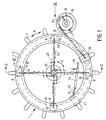
- Figure 1 is a diagrammatic plan view of a transport means, showing parts of gripping means connected thereto as well as parts of the means for driving the transport means.
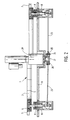
- Figure 2 is a sectional view of Figure 1, seen along the line II - II in Figure 1.
- Figure 3 is view of Figure 1, seen according to arrow III in Figure 1.
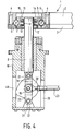
- Figure 4 is a larger-scale sectional view of a part of the transport means and the mechanism for reciprocating the transport means in vertical direction.
- Figure 5 is a view corresponding with Figure 4, in a position in which the transport means has been moved downward in comparison with the position shown in Figure 4.
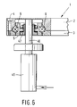
- Figure 6 shows the arrangement of a buffer cylinder supporting the transport means.
- the device comprises an annular transport means 1, which is substantially built up of two annular means 2 and 3, one being supported on the other, which are interconnected by means of bolts 4.
- the transport means is thereby supported by an annular carrier 5, with the interposition of annular bearings 6, which are accommodated within grooves formed in the inner circumference and the outer circumference of the annular carrier 5, as well as in grooves bounded by the annular parts 2 and 3, as will be apparent from Figures 2, 4 and 5.
- Gripping means for disc-shaped registration carriers may be connected, via connecting arms 7, to the annular transport means 1, all this as described in the aforesaid Dutch patent application 9201065.
- the annular carrier 5 having a substantially H-shaped section is supported by a plurality of sliding pieces 8 made up of plungers, which are journalled, in such manner as to capable of vertical sliding movement, in sleeve-shaped means 10 secured to the frame 9 of the device.
- An internally threaded sleeve 11 is thereby screwed on the upper end of each plunger 8.
- At its bottom end said sleeve 11 is provided with a projecting collar 12, on which a web 14 of carrier 5 is supported with the interposition of bearings 13, said web 14 being provided with a bore 16, within which the upper end of plunger 8 is positioned.
- a nut 15 is screwed on that part of the, also externally threaded, sleeve 11 which projects above said web, which nut butts on the upper side of web 14, with the interposition of bearings 16, all this in such a manner that the plunger 8 is connected to the annular carrier 5 in such manner as to be incapable of movement in its longitudinal direction.
- the upper end of a link 18 is hinged to the bottom end of each plunger 8 by means of a horizontally extending pin 17 crossing the central axis of the annular carrier 5 perpendicularly.
- the bottom end of the link 18 is connected to the upper end of a further link 20 by means of a pin 19 extending parallel to pin 17.
- the bottom end of link 20 is hinged, by means of a pin 21 extending parallel to pins 17 and 19, to an ear 22 which is fixedly connected to sleeve 10.
- a connecting rod 23 is hinged to each pivot pin 19 by means of a ball joint.
- the facing ends of the four connecting rod 23 are connected to a disc-shaped means 26 by means of vertical pins 24, with the interposition of a ball joint 25.
- Said disc-shaped means 26 is secured to the outgoing shaft 27 of an electromotor 28, which is disposed in such a manner that the central axis of outgoing shaft 27 coincides with the central axis of annular carrier 5 and the axis of rotation of transport means 1.
- a connecting rod 32 is connected to a support 29 secured to transport means 1, utilizing a vertical pivot pin and a ball joint 31.
- the other end of the connecting rod is connected to a disc 35 by means of a vertical pin and a ball joint 34, said disc being secured to the vertical outgoing shaft 36 of an electromotor 37 mounted on the frame 9 of the device.
- the disc-shaped means 26 can be reciprocated by means of electromotor 28, as indicated by means of arrow C.
- this connecting rods 23 can be pivoted from the position illustrated in full lines in Figure 1 to position 23' illustrated in chain-dotted lines in Figure 1, which results in lengthwise movement of connecting rods 23 in a direction away from sleeves 10.
- this links 18 and 20 will be pivoted from the position shown in Figure 5, in which said links include an angle with each other, to the position shown in Figure 4, in which the links are in line.
- the annular carrier 5, and thus also the annular transport means 1 is lifted from a lower position to an upper position in order to lift objects supported by supporting means, in particular in the shape of registration carriers, from the supporting means supporting the registration carriers.
- the connecting rods 23 can be moved in their longitudinal direction again by rotating the electromotor 28, as a result of which connecting rods 23 will return to the position illustrated in full lines in Figure 1, and the links will be pivoted to the position shown in Figure 5, as a result of which transport means 1 and the gripping means supported by said transport means are moved downward so as to place the registration carriers on the supporting means in the respective stations.
- the drive of the disc-shaped means may also be designed such that the rods 23 can be pivoted in opposite directions from their positions shown in full lines, so that they cannot only be moved to position 23' but also to a similar position on the other side of position 23.
- the wall of the sleeve 10 is formed with two diametrically opposed recesses 38, in order to obtain a compact construction of said sleeve, in which recesses the ends of pin 19 can move, and also with a recess 39 for allowing connecting rod 23 to pass. Furthermore a recess 40 is formed in the wall of sleeve 10, opposite recess 39, in order to prevent the wall of the sleeve 10 from coming into conflict with the links or the end of connecting rod 23 in the position illustrated in Figure 5.
- a connecting rod 42 of a preferably pneumatic buffer cylinder 43 may be secured to a support 41 secured to transport means 1, whilst said buffer cylinder is furthermore hinged to the frame of the device in a hinge point 44.
- the buffer cylinder 43 can be maintained at a desired pressure, so that a force, substantially in the direction according to arrow D, is constantly exerted on transport means 1 via connecting rod 42.
- this transport means 1 is constantly urged in a particular direction with respect to the carrier 5 rotatably supporting said transport means, as a result of which any backlash in the direction of rotation, for example caused by play in bearings 31 and 34, is compensated, in such a manner that any backlash that may be present will not have an adverse effect on the intended movements of transport means 1 about its axis of rotation.
- other means for example magnets, may be provided, which constantly attempt to urge the transport means in a particular direction with respect to the carrier.
- carrier 5 may be supported by a few, preferably pneumatic, buffer cylinders 45, whose vertically extending piston rods 46 can freely slide through sleeves 47, which are of a similar design as sleeves 11 and which are secured to carrier 5 in a similar manner as sleeves 11.
- the upper ends of piston rods 46 butt against parts of transport means 1. It is also possible, however, to design the carrier with a closed underside near the buffer cylinders, whereby the upper ends of the piston rods or supporting parts provided on the upper ends of the piston rods can engage the underside of carrier 5.
- said buffer cylinders are preferably disposed near plungers 8.
- plungers 8 and four buffer cylinders are used In the illustrated embodiment. It will be apparent that also other numbers of buffer cylinders and plungers may be used, and the number of buffer cylinders need not be the same as the number of plungers.
Landscapes
- Engineering & Computer Science (AREA)
- Mechanical Engineering (AREA)
- Specific Conveyance Elements (AREA)
- Manufacturing Optical Record Carriers (AREA)
Applications Claiming Priority (2)
| Application Number | Priority Date | Filing Date | Title |
|---|---|---|---|
| NL9402117 | 1994-12-14 | ||
| NL9402117A NL9402117A (nl) | 1994-12-14 | 1994-12-14 | Inrichting voor het verwerken van voorwerpen. |
Publications (2)
| Publication Number | Publication Date |
|---|---|
| EP0716902A1 true EP0716902A1 (de) | 1996-06-19 |
| EP0716902B1 EP0716902B1 (de) | 1999-08-04 |
Family
ID=19865013
Family Applications (1)
| Application Number | Title | Priority Date | Filing Date |
|---|---|---|---|
| EP95203452A Expired - Lifetime EP0716902B1 (de) | 1994-12-14 | 1995-12-12 | Vorrichtung zum Behandeln von Gegenständen |
Country Status (5)
| Country | Link |
|---|---|
| US (1) | US5906261A (de) |
| EP (1) | EP0716902B1 (de) |
| JP (1) | JPH08244968A (de) |
| DE (1) | DE69511226T2 (de) |
| NL (1) | NL9402117A (de) |
Cited By (1)
| Publication number | Priority date | Publication date | Assignee | Title |
|---|---|---|---|---|
| EP3006382A1 (de) * | 2014-09-09 | 2016-04-13 | Krones Aktiengesellschaft | Greif- und/oder manipulationseinheit und verfahren zur handhabung von objekten |
Families Citing this family (2)
| Publication number | Priority date | Publication date | Assignee | Title |
|---|---|---|---|---|
| US6189680B1 (en) * | 1999-07-27 | 2001-02-20 | Fujikoshi Kikai Kogyo Kabushiki Kaisha | Rotary conveyor |
| CN112828660B (zh) * | 2020-12-31 | 2022-05-24 | 江苏南高智能装备创新中心有限公司 | 一种全自动数控机床加工的桁架机械手 |
Citations (4)
| Publication number | Priority date | Publication date | Assignee | Title |
|---|---|---|---|---|
| US1859111A (en) * | 1927-09-28 | 1932-05-17 | Western Electric Co | Indexing apparatus |
| GB2168447A (en) * | 1984-12-18 | 1986-06-18 | Marconi Instruments Ltd | Toggle-linkage for platen press |
| DE3709354A1 (de) * | 1987-03-21 | 1988-09-29 | Hubert Schulte | Vorrichtung zum taktweisen bewegen von zu bearbeitenden werkstuecken mittels eines drehtisches |
| EP0574975A1 (de) * | 1992-06-16 | 1993-12-22 | ODME International B.V. | Vorrichtung zur Verarbeitung von plattenförmigen Aufzeichnungsträger |
Family Cites Families (3)
| Publication number | Priority date | Publication date | Assignee | Title |
|---|---|---|---|---|
| US2915200A (en) * | 1956-08-09 | 1959-12-01 | Sylvania Electric Prod | Article transfer mechanism |
| US4202435A (en) * | 1978-08-30 | 1980-05-13 | Emerson Electric Co. | Automatic reciprocating, indexing and picking assembly apparatus |
| US4740135A (en) * | 1986-01-08 | 1988-04-26 | Scss Instruments | Wafer transfer arm mechanism |
-
1994
- 1994-12-14 NL NL9402117A patent/NL9402117A/nl not_active Application Discontinuation
-
1995
- 1995-12-12 DE DE69511226T patent/DE69511226T2/de not_active Expired - Fee Related
- 1995-12-12 EP EP95203452A patent/EP0716902B1/de not_active Expired - Lifetime
- 1995-12-12 US US08/570,873 patent/US5906261A/en not_active Expired - Fee Related
- 1995-12-14 JP JP7325964A patent/JPH08244968A/ja active Pending
Patent Citations (4)
| Publication number | Priority date | Publication date | Assignee | Title |
|---|---|---|---|---|
| US1859111A (en) * | 1927-09-28 | 1932-05-17 | Western Electric Co | Indexing apparatus |
| GB2168447A (en) * | 1984-12-18 | 1986-06-18 | Marconi Instruments Ltd | Toggle-linkage for platen press |
| DE3709354A1 (de) * | 1987-03-21 | 1988-09-29 | Hubert Schulte | Vorrichtung zum taktweisen bewegen von zu bearbeitenden werkstuecken mittels eines drehtisches |
| EP0574975A1 (de) * | 1992-06-16 | 1993-12-22 | ODME International B.V. | Vorrichtung zur Verarbeitung von plattenförmigen Aufzeichnungsträger |
Cited By (1)
| Publication number | Priority date | Publication date | Assignee | Title |
|---|---|---|---|---|
| EP3006382A1 (de) * | 2014-09-09 | 2016-04-13 | Krones Aktiengesellschaft | Greif- und/oder manipulationseinheit und verfahren zur handhabung von objekten |
Also Published As
| Publication number | Publication date |
|---|---|
| NL9402117A (nl) | 1996-07-01 |
| EP0716902B1 (de) | 1999-08-04 |
| DE69511226T2 (de) | 1999-12-02 |
| DE69511226D1 (de) | 1999-09-09 |
| US5906261A (en) | 1999-05-25 |
| JPH08244968A (ja) | 1996-09-24 |
Similar Documents
| Publication | Publication Date | Title |
|---|---|---|
| RU2102239C1 (ru) | Устройство для передачи заготовки от первого станка к второму станку | |
| CN111805230A (zh) | 一种自动十字轴装配线 | |
| KR930010310B1 (ko) | 트랜스퍼 프레스용 이송장치와 그 구동 시스템 | |
| US5617944A (en) | Shuttle transfer assembly | |
| AU675249B2 (en) | Stair-like device with moving steps for feeding elongated pieces of wood | |
| CN1451594A (zh) | 在传送线上运输的板状物体的翻转装置 | |
| CN101014450A (zh) | 包括分成两个分离的子组件的用于开动活动元件的装置的并行机器人 | |
| CA2443424A1 (en) | Modular and reconfigurable parallel kinematic robot | |
| US5125497A (en) | Lifting system for lifting goods over a limited distance while maintaining an aligned orientation of the goods with respect to a reference | |
| DK157805B (da) | Apparat til transport af tung last. | |
| KR100346866B1 (ko) | 금속성형기,특히반송프레스의반송장치 | |
| EP0716902B1 (de) | Vorrichtung zum Behandeln von Gegenständen | |
| US5967740A (en) | Device for the transport of objects to a destination | |
| GB2213452A (en) | Walking beam conveyor | |
| JPH07330130A (ja) | コンテナの段階的移送のための搬送装置 | |
| CN108688146B (zh) | 一种fdm打印加工一体机的输送定位装置 | |
| JPH07110292A (ja) | 圧力容器耐圧試験装置 | |
| US5653329A (en) | Accumulating lift and carry conveyer system | |
| RU2057046C1 (ru) | Мобильный шагающий робот | |
| US5190142A (en) | Lift and carry accumulating conveyor | |
| EP1127684A2 (de) | Stösselantriebsvorrichtung für eine Presse | |
| CN215701794U (zh) | 一种间距可调节的机械手装置 | |
| JP3716956B2 (ja) | 搬送装置 | |
| KR101936656B1 (ko) | 곡면 인쇄 장치 | |
| SU1756116A1 (ru) | Многопозиционный станок |
Legal Events
| Date | Code | Title | Description |
|---|---|---|---|
| PUAI | Public reference made under article 153(3) epc to a published international application that has entered the european phase |
Free format text: ORIGINAL CODE: 0009012 |
|
| AK | Designated contracting states |
Kind code of ref document: A1 Designated state(s): CH DE FR GB IT LI NL SE |
|
| 17P | Request for examination filed |
Effective date: 19960717 |
|
| 17Q | First examination report despatched |
Effective date: 19980505 |
|
| GRAG | Despatch of communication of intention to grant |
Free format text: ORIGINAL CODE: EPIDOS AGRA |
|
| GRAG | Despatch of communication of intention to grant |
Free format text: ORIGINAL CODE: EPIDOS AGRA |
|
| GRAH | Despatch of communication of intention to grant a patent |
Free format text: ORIGINAL CODE: EPIDOS IGRA |
|
| GRAH | Despatch of communication of intention to grant a patent |
Free format text: ORIGINAL CODE: EPIDOS IGRA |
|
| GRAA | (expected) grant |
Free format text: ORIGINAL CODE: 0009210 |
|
| AK | Designated contracting states |
Kind code of ref document: B1 Designated state(s): CH DE FR GB IT LI NL SE |
|
| REG | Reference to a national code |
Ref country code: CH Ref legal event code: NV Representative=s name: ROTTMANN, ZIMMERMANN + PARTNER AG Ref country code: CH Ref legal event code: EP |
|
| REF | Corresponds to: |
Ref document number: 69511226 Country of ref document: DE Date of ref document: 19990909 |
|
| ET | Fr: translation filed | ||
| ITF | It: translation for a ep patent filed |
Owner name: STUDIO TORTA S.R.L. |
|
| PLBE | No opposition filed within time limit |
Free format text: ORIGINAL CODE: 0009261 |
|
| STAA | Information on the status of an ep patent application or granted ep patent |
Free format text: STATUS: NO OPPOSITION FILED WITHIN TIME LIMIT |
|
| 26N | No opposition filed | ||
| PGFP | Annual fee paid to national office [announced via postgrant information from national office to epo] |
Ref country code: FR Payment date: 20001026 Year of fee payment: 6 |
|
| PGFP | Annual fee paid to national office [announced via postgrant information from national office to epo] |
Ref country code: DE Payment date: 20001101 Year of fee payment: 6 |
|
| PGFP | Annual fee paid to national office [announced via postgrant information from national office to epo] |
Ref country code: SE Payment date: 20001102 Year of fee payment: 6 |
|
| PGFP | Annual fee paid to national office [announced via postgrant information from national office to epo] |
Ref country code: CH Payment date: 20001129 Year of fee payment: 6 |
|
| PGFP | Annual fee paid to national office [announced via postgrant information from national office to epo] |
Ref country code: GB Payment date: 20001206 Year of fee payment: 6 |
|
| PGFP | Annual fee paid to national office [announced via postgrant information from national office to epo] |
Ref country code: NL Payment date: 20001231 Year of fee payment: 6 |
|
| PG25 | Lapsed in a contracting state [announced via postgrant information from national office to epo] |
Ref country code: GB Free format text: LAPSE BECAUSE OF NON-PAYMENT OF DUE FEES Effective date: 20011212 |
|
| PG25 | Lapsed in a contracting state [announced via postgrant information from national office to epo] |
Ref country code: SE Free format text: LAPSE BECAUSE OF NON-PAYMENT OF DUE FEES Effective date: 20011213 |
|
| PG25 | Lapsed in a contracting state [announced via postgrant information from national office to epo] |
Ref country code: LI Free format text: LAPSE BECAUSE OF NON-PAYMENT OF DUE FEES Effective date: 20011231 Ref country code: CH Free format text: LAPSE BECAUSE OF NON-PAYMENT OF DUE FEES Effective date: 20011231 |
|
| REG | Reference to a national code |
Ref country code: GB Ref legal event code: IF02 |
|
| PG25 | Lapsed in a contracting state [announced via postgrant information from national office to epo] |
Ref country code: NL Free format text: LAPSE BECAUSE OF NON-PAYMENT OF DUE FEES Effective date: 20020701 |
|
| PG25 | Lapsed in a contracting state [announced via postgrant information from national office to epo] |
Ref country code: DE Free format text: LAPSE BECAUSE OF NON-PAYMENT OF DUE FEES Effective date: 20020702 |
|
| EUG | Se: european patent has lapsed |
Ref document number: 95203452.8 |
|
| GBPC | Gb: european patent ceased through non-payment of renewal fee |
Effective date: 20011212 |
|
| REG | Reference to a national code |
Ref country code: CH Ref legal event code: PL |
|
| PG25 | Lapsed in a contracting state [announced via postgrant information from national office to epo] |
Ref country code: FR Free format text: LAPSE BECAUSE OF NON-PAYMENT OF DUE FEES Effective date: 20020830 |
|
| NLV4 | Nl: lapsed or anulled due to non-payment of the annual fee |
Effective date: 20020701 |
|
| REG | Reference to a national code |
Ref country code: FR Ref legal event code: ST |
|
| PG25 | Lapsed in a contracting state [announced via postgrant information from national office to epo] |
Ref country code: IT Free format text: LAPSE BECAUSE OF NON-PAYMENT OF DUE FEES Effective date: 20051212 |