EP0715978A2 - Suspension strut metal-to-metal jounce stop - Google Patents
Suspension strut metal-to-metal jounce stop Download PDFInfo
- Publication number
- EP0715978A2 EP0715978A2 EP95118721A EP95118721A EP0715978A2 EP 0715978 A2 EP0715978 A2 EP 0715978A2 EP 95118721 A EP95118721 A EP 95118721A EP 95118721 A EP95118721 A EP 95118721A EP 0715978 A2 EP0715978 A2 EP 0715978A2
- Authority
- EP
- European Patent Office
- Prior art keywords
- jounce
- canister
- annular
- bumper
- shock
- Prior art date
- Legal status (The legal status is an assumption and is not a legal conclusion. Google has not performed a legal analysis and makes no representation as to the accuracy of the status listed.)
- Withdrawn
Links
Images
Classifications
-
- F—MECHANICAL ENGINEERING; LIGHTING; HEATING; WEAPONS; BLASTING
- F16—ENGINEERING ELEMENTS AND UNITS; GENERAL MEASURES FOR PRODUCING AND MAINTAINING EFFECTIVE FUNCTIONING OF MACHINES OR INSTALLATIONS; THERMAL INSULATION IN GENERAL
- F16F—SPRINGS; SHOCK-ABSORBERS; MEANS FOR DAMPING VIBRATION
- F16F9/00—Springs, vibration-dampers, shock-absorbers, or similarly-constructed movement-dampers using a fluid or the equivalent as damping medium
- F16F9/32—Details
- F16F9/58—Stroke limiting stops, e.g. arranged on the piston rod outside the cylinder
-
- B—PERFORMING OPERATIONS; TRANSPORTING
- B60—VEHICLES IN GENERAL
- B60G—VEHICLE SUSPENSION ARRANGEMENTS
- B60G15/00—Resilient suspensions characterised by arrangement, location or type of combined spring and vibration damper, e.g. telescopic type
- B60G15/02—Resilient suspensions characterised by arrangement, location or type of combined spring and vibration damper, e.g. telescopic type having mechanical spring
- B60G15/06—Resilient suspensions characterised by arrangement, location or type of combined spring and vibration damper, e.g. telescopic type having mechanical spring and fluid damper
- B60G15/062—Resilient suspensions characterised by arrangement, location or type of combined spring and vibration damper, e.g. telescopic type having mechanical spring and fluid damper the spring being arranged around the damper
-
- B—PERFORMING OPERATIONS; TRANSPORTING
- B60—VEHICLES IN GENERAL
- B60G—VEHICLE SUSPENSION ARRANGEMENTS
- B60G2202/00—Indexing codes relating to the type of spring, damper or actuator
- B60G2202/10—Type of spring
- B60G2202/14—Plastic spring, e.g. rubber
- B60G2202/143—Plastic spring, e.g. rubber subjected to compression
-
- B—PERFORMING OPERATIONS; TRANSPORTING
- B60—VEHICLES IN GENERAL
- B60G—VEHICLE SUSPENSION ARRANGEMENTS
- B60G2202/00—Indexing codes relating to the type of spring, damper or actuator
- B60G2202/30—Spring/Damper and/or actuator Units
- B60G2202/31—Spring/Damper and/or actuator Units with the spring arranged around the damper, e.g. MacPherson strut
- B60G2202/312—The spring being a wound spring
-
- B—PERFORMING OPERATIONS; TRANSPORTING
- B60—VEHICLES IN GENERAL
- B60G—VEHICLE SUSPENSION ARRANGEMENTS
- B60G2204/00—Indexing codes related to suspensions per se or to auxiliary parts
- B60G2204/10—Mounting of suspension elements
- B60G2204/12—Mounting of springs or dampers
- B60G2204/125—Mounting of rubber type springs
-
- B—PERFORMING OPERATIONS; TRANSPORTING
- B60—VEHICLES IN GENERAL
- B60G—VEHICLE SUSPENSION ARRANGEMENTS
- B60G2204/00—Indexing codes related to suspensions per se or to auxiliary parts
- B60G2204/10—Mounting of suspension elements
- B60G2204/12—Mounting of springs or dampers
- B60G2204/128—Damper mount on vehicle body or chassis
-
- B—PERFORMING OPERATIONS; TRANSPORTING
- B60—VEHICLES IN GENERAL
- B60G—VEHICLE SUSPENSION ARRANGEMENTS
- B60G2204/00—Indexing codes related to suspensions per se or to auxiliary parts
- B60G2204/40—Auxiliary suspension parts; Adjustment of suspensions
- B60G2204/41—Elastic mounts, e.g. bushings
- B60G2204/4104—Bushings having modified rigidity in particular directions
- B60G2204/41044—Bushings having modified rigidity in particular directions in a shell for being loaded mainly in axial direction, e.g. piston rod mounts, longitudinal push-pull rod mounts
-
- B—PERFORMING OPERATIONS; TRANSPORTING
- B60—VEHICLES IN GENERAL
- B60G—VEHICLE SUSPENSION ARRANGEMENTS
- B60G2204/00—Indexing codes related to suspensions per se or to auxiliary parts
- B60G2204/40—Auxiliary suspension parts; Adjustment of suspensions
- B60G2204/41—Elastic mounts, e.g. bushings
- B60G2204/4108—Resilient element being enclosed and or pres-tressed in a solid container
-
- B—PERFORMING OPERATIONS; TRANSPORTING
- B60—VEHICLES IN GENERAL
- B60G—VEHICLE SUSPENSION ARRANGEMENTS
- B60G2204/00—Indexing codes related to suspensions per se or to auxiliary parts
- B60G2204/40—Auxiliary suspension parts; Adjustment of suspensions
- B60G2204/418—Bearings, e.g. ball or roller bearings
-
- B—PERFORMING OPERATIONS; TRANSPORTING
- B60—VEHICLES IN GENERAL
- B60G—VEHICLE SUSPENSION ARRANGEMENTS
- B60G2204/00—Indexing codes related to suspensions per se or to auxiliary parts
- B60G2204/40—Auxiliary suspension parts; Adjustment of suspensions
- B60G2204/45—Stops limiting travel
- B60G2204/4502—Stops limiting travel using resilient buffer
- B60G2204/45021—Stops limiting travel using resilient buffer for limiting upper mount movement of a McPherson strut
Definitions
- This invention relates to automotive suspensions and more particularly to an improved shock-absorbing assembly providing a metal-to-metal jounce stop arrangement which allows increased wheel travel during full jounce stroke while insuring extended service life for the elastomeric jounce bumper surrounding the shock piston rod.
- the Ferrel assembly comprises an upper mounted seat assembly including an inverted cup member having an upper body portion and a lower neck portion joined by an integral reverse-bend stop flange.
- a convoluted elastomeric sleeve having its upper end fixed to the cup neck portion, extends axially a predetermined distance surrounding the upper end of the strut outer casing with the suspension strut supporting the vehicle in its statically loaded or design state.
- the suspension strut outer support casing includes a contact ring adapted to engage the convoluted sleeve providing jounce bumper cushioning of the strut.
- the U.S. Patent 4,478,396 issued Oct. 23, 1984 to Kawaura discloses an elastic support structure for a vehicle suspension shock comprising a first rigid member to be subjected to shocks and vibrations produced in a wheel assembly, a second rigid member to which shocks and vibrations may be transferred from the first rigid member, and an elastic member composed of at least two segments similar in geometry constructed independently of each other formed with annular grooves.
- the U.S. Patent 5,078,370 issued January 7, 1992 to McClellan is an example of a vehicle front suspension strut having integrated jounce and rebound stops.
- the suspension spring rebound load is placed on a lower rebound stop member of the mount and the suspension jounce load is placed on an upper jounce stop member of the mount.
- the arrangement results in achieving maximum jounce travel while limiting compression of the jounce bumper to a predetermined axial dimension thereby substantially increasing its service life.
- An additional advantage of the arrangement is that the canister concentrically surrounds the jounce bumper with the assembly in its maximum jounce mode thereby shielding the compressed bumper against damage.
- the ring lower end terminates in a return bent exterior flanged hem circumscribing the ring such that the flanged hem and the canister exterior define common concentric surfaces.
- the inturned shoulder and axial spaced flanged hem upper edge define an external annular groove sized to capture an internal locking rib of a flexible dust tube thereby retaining the tube during reciprocal travel of the assembly.
- a portion of a vehicle front suspension shock-absorbing assembly 10 in its neutral mode incorporating a hydraulic shock-absorbing unit 11 interconnecting the vehicle sprung mass or body portion and a vehicle unsprung mass supported by a front wheel 12.
- the shock-absorbing unit 11 has a mounting bracket, partially depicted at 13, connected to a steering knuckle (not shown).
- the mounting bracket provides a lower support for outer cylindrical support strut tube 14 of the unit 11 which extends upwardly therefrom with the tube secured in the lower bracket 13 as by welding.
- the upper end of the unit 11 is closed by upper cap 16, welded or otherwise secured to the support tube 14.
- a cylindrical piston rod 17 extends axially upwardly from a conventional valved piston (not shown) slidably mounted in a cylindrical inner tube (not shown) radially spaced inwardly from the unit support tube 14 which provides a reservoir for the hydraulic dampening fluid of the shock absorbing unit 11.
- the piston rod 17 is removably attached to an improved upper low profile shock absorber upper mount generally indicated at 20.
- the rod 17 is disposed in telescoping relationship with the unit 11 whereby shocks are absorbed as the rod telescopes into the unit.
- the upper mount 20 comprises an outer two-part housing defined by an upper hat-shaped closure 21 and a lower closure 22.
- Each closure is in the form of one-piece members formed of sheet metal, adapted to house a composite isolator mount 24 in an axially pre-loaded manner.
- the upper mount 20 further comprises an annular inner cup 32 and an elastomeric ring 33 concentrically disposed about the shock principal axis "A".
- the inner cup 32 has a closed bottom wall 34 formed with a central hole 36 having its center aligned on the shock axis so as to receive therethrough the piston rod upper threaded portion 18 for threaded attachment by nut 38.
- the cup 32 has an upstanding cylindrical inner side wall 40 terminating at its upper end in jounce stop means in the form of an annular end 42.
- the hat-shaped upper closure member 21 is formed with a cylindrical axially upstanding outer wall portion 51 concentrically disposed around the cup inner side wall 40 defining an annular space therebetween.
- the upper closure member wall portion 51 has its lower end terminating in a radially outwardly extending attaching flanged brim 52.
- the flanged brim 52 is removably fixed to a vehicle body strut receiving sheet metal panel or tower 55, as by bolts 56, extending through holes 57 upon the assembly 10 being positioned in panel circular opening 58.
- the upper closure member 21 terminates at its upper end in a horizontal annular cap ring 64 forming a central access aperture 65.
- the lower closure member 22 defines a circular base collar 70 having a central flanged opening defined by a down-turned annular flange 72 concentrically disposed about the principal axis "A".
- the collar 70 is shown boarded by an upwardly and outwardly diverging wall portion 73 having its upper terminus formed with an outwardly bowed annular seat portion 74.
- the shoulder portion 74 terminates at its upper end in a radially outwardly extending terminal flange 76 in subjacent flatwise contact with the underside of the cover member flanged brim 52.
- the collar 70 and its down-turned flange 72 is disposed above a subjacent upturned annular flange 78 and radially inwardly extending central base disc 79 of upper coil spring seat 80.
- an annular cavity is formed sized to snugly receive therein a circular ball bearing ring assembly 82 concentrically disposed about the axis "A".
- the upper annular spring seat 80 is resiliently supported on the upper end coil of an helical suspension coil spring generally indicated at 84.
- the coil spring 84 spirals around the shock outer support tube 14 and extends upwardly from an annular lower spring support seat member 86 axially positioned above the mounting bracket 13.
- the member 86 has an upstanding neck portion 87 welded or otherwise secured to the support tube 14.
- the upper one-piece sheet metal spring seat 80 is formed with an outer upwardly opening U-sectioned trough section defined by a radially extending lower bight wall 88 and an inner downwardly opening U-sectioned trough section defined by a radially extending upper bight wall 89.
- the inner trough section bight wall 89 concentrically surrounds the ball bearing assembly 82 while the outer trough section bight wall 88 concentrically surrounds an upper portion of an elastomeric jounce bumper 90.
- the jounce bumper 90 has an axial bore 91 receiving therethrough, in a press-fit manner, an upper portion of the shock piston rod 18.
- FIG. 1 shows the outer trough lower bight wall 88 and the inner trough upper bight wall 89 interconnected by a common flange 92 shown angled upwardly and inwardly from the radially extending outer bight wall 88 to the radially extending inner bight wall 89.
- a concentric vertically disposed cylindrical canister 94 has an upper open end sized to snugly encircle the spring seat upturned annular flange 78.
- the canister 94 upper end terminates in an out-turned radial collar 96 adapted for flush attachment, as by spot welds, with an opposed underside of spring seat upper bight wall 89.
- the canister 94 which is concentrically disposed about the strut axis "A", extends downwardly from the spring seat a predetermined dimension with a lower portion thereof formed with an integral inturned annular shoulder 97.
- the shoulder 97 has depending therefrom a reduced diameter concentric ring 98 terminating in a return bent flanged hem 99 folded back upon the ring exterior surface.
- the hem 99 free end is axially spaced a predetermined dimension from the shoulder 97 so as to form an external annular groove 100.
- the groove 100 is sized to receive therein an annular rib 102 formed on the internal surface of upper neck portion 104 provided on an elastomeric flexible accordion-like dust tube 106.
- the dust tube 106 encircles the upper portion of the strut cylinder 14 with the dust tube lower extremity 108 shown contacting high surface 109 of lower coil spring seat 110.
- the strut cylinder 14 upper end cap 16 is shown supporting a striker plate 112 formed with an annular downwardly off-set radially extending lower stopper ledge 114. It will be seen that the concentric stopper ledge 114 is in vertically spaced subjacent alignment with the annular folded upper stopper edge juncture 116 of the canister 94. Thus, as seen in Fig. 2, with the shock-absorbing assembly 10 in its maximum jounce mode the upper stopper juncture 116 is shown contacting the lower stopping ledge 114 providing a metal-to-metal jounce stop arrangement.
- the jounce bumper 90 is compressed to a predetermined axial dimension "Z" in its maximum jounce mode so as to be completely shielded by the canister 96 thereby obviating possible damage to the bumper.
- damage could occur with an unshielded bumper wherein the shock axis is moved off-center during full jounce resulting in asymmetric outward radial bumper expansion causing the bumper to be sheared or cut by the canister lower extremity.
- the bumper is axially spaced from the metal-to-metal jounce stop contact area between the lower stopper ledge 114 and upper stopper juncture 116 further insuring against damage to the bumper 90.
- the striker plate 112 is formed with a frusto-conical shaped skirt 120 adapted to provide a lead-in surface for the canister stopper juncture 116.
- the lead-in skirt 120 tends to correct for axial misalignment between the canister lower extremity and the jounce lower stopper ledge 114.
- the jounce bumper 90 has an upper end face 122 in flush abutment with the underside of the spring seat 80.
- the bumper 90 lower end face 124 is shown axially spaced a predetermined dimension "X" from the striker plate upper opposed surface 126. It will be noted that the dimension "X" defines the free vertical travel of the jounce bumper 90 prior to its lower end face 124 contacting the striker plate upper surface 126.
- the jounce bumper exterior is shown formed with a plurality of annular convolute portions 128 about which the bumper folds when undergoing axial compression between the spring seat central disc 79 and opposed striker plate upper surface 126.
- Fig. 1 it will be seen that the canister lower extremity, in the form of annular folded stopping juncture 116, is axially spaced a predetermined dimension "Y" from the vertically aligned annular stopper ledge 114.
- the dimension "Y" defines the potential or maximum axial jounce travel when the assembly 10 is in its design static mode.
- the jounce bumper undergoes a maximum compression set by predetermined axial dimension "Z".
- the dimension "Z" defines the vertical height of bumper chamber 130 provided at the full jounce mode.
Abstract
An automotive vehicle suspension shock-absorbing assembly providing a metal-to-metal jounce stop arrangement. The lower extremity of a cylindrical canister, extending downwardly from an upper coil spring seat, defines an upper angular jounce stopper while a striker plate, fixed on the upper end of a shock-absorber unit, is formed with a downwardly off-set annular lower stopper ledge. The arrangement enables maximum jounce travel while limiting compression of the elastomeric jounce bumper, encircling the shock piston rod, to a predetermined axial dimension thereby substantially increasing its service life. Further, the canister shields the bumper during full jounce obviating damage thereto. The canister lower end portion has an inturned shoulder from which an inwardly off-set ring depends terminating in an exterior return bent hem flange. The return flange upper free edge is axially spaced subjacent the inturned shoulder providing an external annular groove sized to capture an elastomeric dust shield retaining rib.
Description
- This invention relates to automotive suspensions and more particularly to an improved shock-absorbing assembly providing a metal-to-metal jounce stop arrangement which allows increased wheel travel during full jounce stroke while insuring extended service life for the elastomeric jounce bumper surrounding the shock piston rod.
- An example of a suspension strut upper support mount having an improved spring characteristic is found in U.S. Patent 4,465,296 issued August 14, 1984 to Shiratori et al. The invention provides a rubber block having a predetermined configuration for receiving oscillating loads in a relatively smooth manner.
- The U.S. Patent 4,747,587 issued May 31, 1988 to Ferrel, assigned to the assignee of the present application, discloses a low profile strut isolator and jounce bumper upper mount providing a compact resilient assembly adaptable for a vehicle having a reduced hood line. The Ferrel assembly comprises an upper mounted seat assembly including an inverted cup member having an upper body portion and a lower neck portion joined by an integral reverse-bend stop flange. A convoluted elastomeric sleeve, having its upper end fixed to the cup neck portion, extends axially a predetermined distance surrounding the upper end of the strut outer casing with the suspension strut supporting the vehicle in its statically loaded or design state. The suspension strut outer support casing includes a contact ring adapted to engage the convoluted sleeve providing jounce bumper cushioning of the strut.
- The U.S. Patent 4,478,396 issued Oct. 23, 1984 to Kawaura discloses an elastic support structure for a vehicle suspension shock comprising a first rigid member to be subjected to shocks and vibrations produced in a wheel assembly, a second rigid member to which shocks and vibrations may be transferred from the first rigid member, and an elastic member composed of at least two segments similar in geometry constructed independently of each other formed with annular grooves.
- The U.S. Patent 5,078,370 issued January 7, 1992 to McClellan is an example of a vehicle front suspension strut having integrated jounce and rebound stops. In the McClellan patent the suspension spring rebound load is placed on a lower rebound stop member of the mount and the suspension jounce load is placed on an upper jounce stop member of the mount.
- The U.S. Patent 4,934,730 issued June 19, 1990 to Okuzumiis an example of a vehicle front suspension strut wherein the upper end of the strut piston rod is engaged in an inner sleeve of a mount insulator for limited axial movement relative to the inner sleeve.
- It is a feature of the present invention to provide a shock-absorbing assembly for use in a vehicle suspension having an improved metal-to-metal stop arrangement enabling maximum jounce travel while limiting resultant compression of an elastomeric jounce bumper on the shock piston rod to a predetermined axial dimension thereby substantially increasing the service life of the bumper.
- It is a further feature of the present invention to provide an improved shock-absorbing assembly metal-to-metal jounce stop for use in a vehicle suspension as set forth above wherein the lower extremity of a cylindrical canister, which axially extends from an upper spring seat of the assembly, defines an annular upper jounce stopper adapted to contact an annular lower jounce stopper off-set axially below the upper end of the shock cylinder. The arrangement results in achieving maximum jounce travel while limiting compression of the jounce bumper to a predetermined axial dimension thereby substantially increasing its service life. An additional advantage of the arrangement is that the canister concentrically surrounds the jounce bumper with the assembly in its maximum jounce mode thereby shielding the compressed bumper against damage.
- It is still another object of the present invention to provide an improved shock-absorbing suspension strut assembly as set forth above wherein the cylindrical canister lower end is formed with an inturned shoulder defining a depending reduced diameter ring. The ring lower end terminates in a return bent exterior flanged hem circumscribing the ring such that the flanged hem and the canister exterior define common concentric surfaces. The inturned shoulder and axial spaced flanged hem upper edge define an external annular groove sized to capture an internal locking rib of a flexible dust tube thereby retaining the tube during reciprocal travel of the assembly.
- These and other objects and advantages of the present invention will be readily apparent by reference to the following description of the preferred embodiment and the accompanying drawing which shows a vehicle suspension strut incorporating the improved upper mount and related structure.
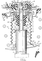
- Fig. 1 is a fragmentary front view, partly in cross section, of a suspension shock-absorbing assembly in its neutral mode incorporating a metal-to-metal jounce stop arrangement in accordance with the present invention; and
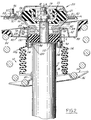
- Fig. 2 is a view similar to Fig. 1 showing the shock absorbing assembly in its maximum jounce mode.
- Referring now to the drawing, there is shown in Fig. 1 a portion of a vehicle front suspension shock-absorbing
assembly 10 in its neutral mode incorporating a hydraulic shock-absorbing unit 11 interconnecting the vehicle sprung mass or body portion and a vehicle unsprung mass supported by afront wheel 12. The shock-absorbing unit 11 has a mounting bracket, partially depicted at 13, connected to a steering knuckle (not shown). The mounting bracket provides a lower support for outer cylindricalsupport strut tube 14 of the unit 11 which extends upwardly therefrom with the tube secured in thelower bracket 13 as by welding. The upper end of the unit 11 is closed byupper cap 16, welded or otherwise secured to thesupport tube 14. Reference may be had to the U.S. patent 5,078,370, mentioned above, which patent discloses details of conventional shock absorber components and is incorporated by reference herein. - A
cylindrical piston rod 17 extends axially upwardly from a conventional valved piston (not shown) slidably mounted in a cylindrical inner tube (not shown) radially spaced inwardly from theunit support tube 14 which provides a reservoir for the hydraulic dampening fluid of the shock absorbing unit 11. Thepiston rod 17, which extends upwardly through an opening in the upper cap, has a reduced diameter threadedupper portion 18 terminating in anupper hex end 19. Thepiston rod 17 is removably attached to an improved upper low profile shock absorber upper mount generally indicated at 20. Thus, therod 17 is disposed in telescoping relationship with the unit 11 whereby shocks are absorbed as the rod telescopes into the unit. As seen in Fig 1, theupper mount 20 comprises an outer two-part housing defined by an upper hat-shaped closure 21 and alower closure 22. Each closure is in the form of one-piece members formed of sheet metal, adapted to house acomposite isolator mount 24 in an axially pre-loaded manner. - The
upper mount 20 further comprises an annularinner cup 32 and anelastomeric ring 33 concentrically disposed about the shock principal axis "A". Theinner cup 32 has a closed bottom wall 34 formed with acentral hole 36 having its center aligned on the shock axis so as to receive therethrough the piston rod upper threadedportion 18 for threaded attachment bynut 38. Thecup 32 has an upstanding cylindricalinner side wall 40 terminating at its upper end in jounce stop means in the form of anannular end 42. - The hat-shaped
upper closure member 21 is formed with a cylindrical axially upstandingouter wall portion 51 concentrically disposed around the cupinner side wall 40 defining an annular space therebetween. The upper closuremember wall portion 51 has its lower end terminating in a radially outwardly extending attaching flangedbrim 52. Theflanged brim 52 is removably fixed to a vehicle body strut receiving sheet metal panel ortower 55, as bybolts 56, extending throughholes 57 upon theassembly 10 being positioned in panelcircular opening 58. - The
upper closure member 21 terminates at its upper end in a horizontal annular cap ring 64 forming acentral access aperture 65. Thelower closure member 22 defines a circular base collar 70 having a central flanged opening defined by a down-turnedannular flange 72 concentrically disposed about the principal axis "A". The collar 70 is shown boarded by an upwardly and outwardly divergingwall portion 73 having its upper terminus formed with an outwardly bowedannular seat portion 74. Theshoulder portion 74 terminates at its upper end in a radially outwardly extendingterminal flange 76 in subjacent flatwise contact with the underside of the cover member flangedbrim 52. - The collar 70 and its down-turned
flange 72 is disposed above a subjacent upturnedannular flange 78 and radially inwardly extendingcentral base disc 79 of uppercoil spring seat 80. As a result an annular cavity is formed sized to snugly receive therein a circular ballbearing ring assembly 82 concentrically disposed about the axis "A". - The upper
annular spring seat 80 is resiliently supported on the upper end coil of an helical suspension coil spring generally indicated at 84. Thecoil spring 84 spirals around the shockouter support tube 14 and extends upwardly from an annular lower springsupport seat member 86 axially positioned above themounting bracket 13. Themember 86 has anupstanding neck portion 87 welded or otherwise secured to thesupport tube 14. - The upper one-piece sheet
metal spring seat 80 is formed with an outer upwardly opening U-sectioned trough section defined by a radially extendinglower bight wall 88 and an inner downwardly opening U-sectioned trough section defined by a radially extendingupper bight wall 89. It will be noted that the inner troughsection bight wall 89 concentrically surrounds the ball bearingassembly 82 while the outer troughsection bight wall 88 concentrically surrounds an upper portion of anelastomeric jounce bumper 90. Thejounce bumper 90 has anaxial bore 91 receiving therethrough, in a press-fit manner, an upper portion of theshock piston rod 18. Fig. 1 shows the outer troughlower bight wall 88 and the inner troughupper bight wall 89 interconnected by acommon flange 92 shown angled upwardly and inwardly from the radially extendingouter bight wall 88 to the radially extendinginner bight wall 89. - A concentric vertically disposed
cylindrical canister 94 has an upper open end sized to snugly encircle the spring seat upturnedannular flange 78. Thecanister 94 upper end terminates in an out-turnedradial collar 96 adapted for flush attachment, as by spot welds, with an opposed underside of spring seatupper bight wall 89. Thecanister 94, which is concentrically disposed about the strut axis "A", extends downwardly from the spring seat a predetermined dimension with a lower portion thereof formed with an integral inturnedannular shoulder 97. - The
shoulder 97 has depending therefrom a reduced diameterconcentric ring 98 terminating in a return bent flangedhem 99 folded back upon the ring exterior surface. The hem 99 free end is axially spaced a predetermined dimension from theshoulder 97 so as to form an externalannular groove 100. Thegroove 100 is sized to receive therein anannular rib 102 formed on the internal surface ofupper neck portion 104 provided on an elastomeric flexible accordion-like dust tube 106. Thedust tube 106 encircles the upper portion of thestrut cylinder 14 with the dust tubelower extremity 108 shown contactinghigh surface 109 of lowercoil spring seat 110. - As viewed in Fig. 1 the
strut cylinder 14upper end cap 16 is shown supporting astriker plate 112 formed with an annular downwardly off-set radially extendinglower stopper ledge 114. It will be seen that theconcentric stopper ledge 114 is in vertically spaced subjacent alignment with the annular folded upperstopper edge juncture 116 of thecanister 94. Thus, as seen in Fig. 2, with the shock-absorbingassembly 10 in its maximum jounce mode theupper stopper juncture 116 is shown contacting thelower stopping ledge 114 providing a metal-to-metal jounce stop arrangement. - As viewed in Fig. 2 the
jounce bumper 90 is compressed to a predetermined axial dimension "Z" in its maximum jounce mode so as to be completely shielded by thecanister 96 thereby obviating possible damage to the bumper. Such damage could occur with an unshielded bumper wherein the shock axis is moved off-center during full jounce resulting in asymmetric outward radial bumper expansion causing the bumper to be sheared or cut by the canister lower extremity. It will be appreciated that, by virtue of thestopper ledge 114 being off-set below the striker plateupper contact surface 126, the bumper is axially spaced from the metal-to-metal jounce stop contact area between thelower stopper ledge 114 andupper stopper juncture 116 further insuring against damage to thebumper 90. - It will be further noted that the
striker plate 112 is formed with a frusto-conicalshaped skirt 120 adapted to provide a lead-in surface for thecanister stopper juncture 116. The lead-inskirt 120 tends to correct for axial misalignment between the canister lower extremity and the jouncelower stopper ledge 114. - With reference to Fig. 1 it will be seen that the
jounce bumper 90 has anupper end face 122 in flush abutment with the underside of thespring seat 80. Thebumper 90lower end face 124 is shown axially spaced a predetermined dimension "X" from the striker plate upperopposed surface 126. It will be noted that the dimension "X" defines the free vertical travel of thejounce bumper 90 prior to itslower end face 124 contacting the striker plateupper surface 126. The jounce bumper exterior is shown formed with a plurality of annularconvolute portions 128 about which the bumper folds when undergoing axial compression between the spring seatcentral disc 79 and opposed striker plateupper surface 126. - In Fig. 1 it will be seen that the canister lower extremity, in the form of annular folded stopping
juncture 116, is axially spaced a predetermined dimension "Y" from the vertically alignedannular stopper ledge 114. The dimension "Y" defines the potential or maximum axial jounce travel when theassembly 10 is in its design static mode. - It will be observed that with the
assembly 10 in its full or maximum jounce mode of Fig. 2 the jounce bumper undergoes a maximum compression set by predetermined axial dimension "Z". The dimension "Z" defines the vertical height ofbumper chamber 130 provided at the full jounce mode. By virtue of providing a metal-to-metal full jounce stop while limiting the degree of bumper compression to a predetermined applicant has greatly extended the service life of the bumper elastomeric material. It will be further observed in Fig. 2 that upon the canister lowerextremity stopper juncture 116 contacting the strikerplate stopper flange 114 the canister not only surrounds thecompressed bumper 90 but extends a predetermined dimension below the bumperlower end face 124. As a result each bumper convolute 128, upon being bowed radially outwardly, is contained within thechamber 130 thereby obviating damage thereto.
Claims (5)
- A shock-absorbing assembly for use in a suspension system for an automotive vehicle, the assembly operatively connected between sprung and unsprung masses of the vehicle, the assembly comprising a shock unit having a piston rod extending through an opening in one upper end thereof disposed for reciprocal movement along the principal axis of said unit, the assembly operatively connected between sprung and unsprung masses of a vehicle, a mount fixed on the upper end of the piston rod adapted for attachment to the sprung mass, an annular support member located subjacent the upper mount, a metal-to-metal jounce stop arrangement for the assembly comprising:
means supporting an annular radially extending jounce stopper ledge adjacent said unit upper end;
a cylindrical metal canister fixed to and extending downwardly from an underside of the support member concentrically disposed on said unit principal axis, an elastomeric jounce bumper concentrically positioned on an upper portion of the rod having an upper end face in flush abutment with a central portion of the support member and a lower end face spaced a predetermined dimension above said unit upper end with the assembly in a static design mode;
said canister in said design mode concentrically encircling an upper portion of said bumper with its lower extremity defining an annular stopper edge vertically positioned intermediate said bumper upper and lower end faces so as to define a predetermined maximum axial jounce dimension between said canister stopper edge and said unit stopper ledge;
wherein upon the assembly undergoing maximum jounce travel said canister stopper edge contacting said unit stopper ledge said jounce bumper being compressed a predetermined axial dimension between said support plate and said unit upper end obviating over-compression of said bumper thereby increasing the service-life thereof. - The shock-absorbing assembly as set forth in claim 1, wherein said supporting means in the form of an annular striker plate fixed on said unit upper end, said striker plate bordered by a downwardly and outwardly extending frusto-conical shaped skirt terminating in said annular stopper ledge, said striker plate skirt adapted to provide a lead-in surface for said canister stopper edge.
- The shock absorbing assembly as set forth in claim 1, wherein a lower end portion of said canister formed with an annular inturned shoulder, a concentric ring portion depending from said shoulder portion and terminating in a return bent flanged hem surrounding the exterior of said ring portion, whereby said flanged hem defining a free upper edge spaced a predetermined axial dimension below said inturned shoulder so as to form therewith an annular groove, said groove adapted to receive therein an annular rib formed on an internal surface of an elastomeric dust tube thereby retaining said dust tube in a concentric shielding manner about said unit,
and wherein said canister stopper edge in the form of an annular folded end juncture defined by said return bent flanged hem. - The shock absorbing assembly as set forth in claim 1, wherein said support member comprising an upper coil spring seat formed with a central annular base disc encircled by an upturned concentric annular flange, said upturned flange formed with a radially outwardly extending upper bight wall terminating in a down-turned flange, whereby said upturned flange, said upper bight wall and said down-turned flange defining a downwardly opening U-sectioned trough.
- The shock absorbing assembly as set forth in claim 4, wherein said canister formed at its upper extremity with a radially outwardly extending flanged collar, said canister upper open end having an internal diameter sized so as to snugly encircle said spring seat base disc upturned flange, such that said canister flanged collar in flush welded abutment with an undersurface of said spring seat bight wall.
Applications Claiming Priority (2)
| Application Number | Priority Date | Filing Date | Title |
|---|---|---|---|
| US349297 | 1994-12-05 | ||
| US08/349,297 US5487535A (en) | 1994-12-05 | 1994-12-05 | Suspension strut metal-to-metal jounce stop |
Publications (2)
| Publication Number | Publication Date |
|---|---|
| EP0715978A2 true EP0715978A2 (en) | 1996-06-12 |
| EP0715978A3 EP0715978A3 (en) | 1997-03-26 |
Family
ID=23371761
Family Applications (1)
| Application Number | Title | Priority Date | Filing Date |
|---|---|---|---|
| EP95118721A Withdrawn EP0715978A3 (en) | 1994-12-05 | 1995-11-28 | Suspension strut metal-to-metal jounce stop |
Country Status (4)
| Country | Link |
|---|---|
| US (1) | US5487535A (en) |
| EP (1) | EP0715978A3 (en) |
| JP (1) | JPH08230431A (en) |
| CA (1) | CA2163385A1 (en) |
Cited By (10)
| Publication number | Priority date | Publication date | Assignee | Title |
|---|---|---|---|---|
| DE19719301A1 (en) * | 1997-05-07 | 1998-11-12 | Opel Adam Ag | Structure-side mounting for a shock absorber on a motor vehicle |
| CN100480077C (en) * | 2003-07-16 | 2009-04-22 | 东海橡胶工业株式会社 | Dustproof cover impingement plate and suspension mechanism with the same |
| DE102006056691B4 (en) * | 2005-12-01 | 2009-10-22 | GM Global Technology Operations, Inc., Detroit | Shock absorber assembly with integrated travel limit |
| DE102009022063A1 (en) * | 2009-05-20 | 2010-11-25 | Zf Friedrichshafen Ag | Vibration damper, has retaining pot exhibiting inner diameter larger than outer diameter of front-sided stop surface, where pot is in axial overlap with outer lateral surface of cylinder from defined engaging position |
| CN102514460A (en) * | 2011-12-23 | 2012-06-27 | 上汽通用五菱汽车股份有限公司 | Separation buffering type shock absorber strut and automobile |
| CN103204041A (en) * | 2013-05-03 | 2013-07-17 | 无锡市中捷减震器有限公司 | Top protection plate device of automobile shock absorber |
| CN104968513A (en) * | 2012-12-31 | 2015-10-07 | 巴斯夫欧洲公司 | Jounce bumper assembly |
| CN105711369A (en) * | 2016-01-15 | 2016-06-29 | 东风柳州汽车有限公司 | McPherson suspension overhead support with dual-channel force transferring function |
| CN106151345A (en) * | 2015-04-27 | 2016-11-23 | 株式会社万都 | The top installation structure of front damper |
| US11953096B2 (en) | 2022-04-18 | 2024-04-09 | Schaeffler Technologies AG & Co. KG | Strut bearing assembly with metal guide ring and spring seat |
Families Citing this family (52)
| Publication number | Priority date | Publication date | Assignee | Title |
|---|---|---|---|---|
| US5775720A (en) * | 1996-10-03 | 1998-07-07 | Ford Global Technologies, Inc. | Shock absorbing apparatus |
| DE19752268A1 (en) * | 1997-11-26 | 1999-05-27 | Schaeffler Waelzlager Kg | Suspension strut for vehicle wheel bearing |
| US6257605B1 (en) | 1997-06-30 | 2001-07-10 | Ina Walzlager Schaeffler Ohg | Suspension strut bearing |
| US6126155A (en) * | 1998-11-06 | 2000-10-03 | Chrysler Corporation | Breaking and upper spring seat assembly for a spring and strut module of an automotive vehicle |
| US6161822A (en) * | 1998-11-06 | 2000-12-19 | General Motors Corporation | Single point attachment mount |
| DE19908607B4 (en) * | 1999-02-27 | 2005-05-12 | Daimlerchrysler Ag | Air strut for suspension of motor vehicles |
| US6149171A (en) * | 1999-03-31 | 2000-11-21 | Daimlerchrysler Corporation | Spring isolator for a motor vehicle suspension |
| FR2793732B1 (en) * | 1999-05-17 | 2001-06-22 | Peugeot Citroen Automobiles Sa | DEVICE FOR TOP FIXING A SUSPENSION SHOCK ABSORBER OF A FRONT WHEEL OF A MOTOR VEHICLE |
| US6186486B1 (en) | 1999-07-30 | 2001-02-13 | Delphi Technologies, Inc. | Jounce bumper plate |
| DE19935391B4 (en) * | 1999-07-30 | 2005-09-08 | Carl Freudenberg Kg | Suspension strut |
| US6607186B2 (en) * | 2000-05-01 | 2003-08-19 | Bret Voelkel | Shock absorber |
| WO2002006699A1 (en) * | 2000-07-17 | 2002-01-24 | Peugeot Citroen Automobiles S.A. | Travel limit stop device for a motor vehicle damper, and method for making same |
| DE10047773A1 (en) * | 2000-09-27 | 2002-04-18 | Ina Schaeffler Kg | Axial roller bearing for strut in car wheel suspension has inner ring mounted on upper surface of strut and outer ring connected via flexible layer to mounting on chassis which contains reinforcing frame, part of which forms outer ring |
| US6508342B2 (en) * | 2001-04-06 | 2003-01-21 | Delphi Technologies, Inc. | Damper with integrated dust tube and rate surface |
| AT411349B (en) * | 2001-12-11 | 2003-12-29 | Siemens Sgp Verkehrstech Gmbh | SUSPENSION DEVICE |
| KR100503272B1 (en) | 2002-03-07 | 2005-07-25 | 기아자동차주식회사 | Vehicle suspension |
| KR100488786B1 (en) * | 2002-05-15 | 2005-05-12 | 기아자동차주식회사 | Fluid compressed strut mounting structure |
| US20040089990A1 (en) * | 2002-06-06 | 2004-05-13 | Labeau George A. | Single point attachment dual path suspension mount |
| DE10308193B4 (en) * | 2003-02-25 | 2005-02-03 | Zf Sachs Ag | Suspension strut with a stop buffer |
| DE102004021497A1 (en) * | 2004-04-30 | 2005-12-01 | Zf Friedrichshafen Ag | Suspension strut |
| JP2006002796A (en) * | 2004-06-15 | 2006-01-05 | Toyota Motor Corp | Suspension structure for vehicle |
| US20060001205A1 (en) * | 2004-06-30 | 2006-01-05 | Irfan Raza | Jounce bumper |
| US7178796B2 (en) * | 2004-11-29 | 2007-02-20 | Freudenberg-Nok General Partnership | Rate stiffening jounce bumper assembly |
| US20060272911A1 (en) * | 2005-06-02 | 2006-12-07 | Freudenberg-Nok General Partnership | Jounce bumper, rate cup, and strut mount bottom plate |
| US7338040B2 (en) * | 2005-06-14 | 2008-03-04 | Freudenberg-Nok General Partnership | High retention strength jounce bumper assembly |
| DE102005031012A1 (en) * | 2005-07-02 | 2007-01-18 | Zf Friedrichshafen Ag | Impact stop for vibration damper, has sleeve-shaped safety stop determining minimum operating time of impact stop, when safety stop comes to surface of vibration damper, where surface faces impact stop |
| US7281705B2 (en) * | 2005-07-22 | 2007-10-16 | Basf Corporation | Jounce assembly for a suspension system |
| EP2110273B1 (en) * | 2008-04-18 | 2013-03-27 | Fiat Group Automobiles S.p.A. | Resilient support device for the upper end of the stem of a shock-absorber of a motor-vehicle suspension |
| FR2934656B1 (en) * | 2008-08-01 | 2013-05-17 | Skf Ab | SUSPENSION STOP DEVICE AND FORCE LEG. |
| US20100127437A1 (en) * | 2008-11-25 | 2010-05-27 | Freudenberg-Nok General Partnership | Tolerance Eliminating Assembly Retainer |
| DE102009027319A1 (en) * | 2009-06-30 | 2011-01-05 | Ford Global Technologies, LLC, Dearborn | Elastic bush |
| US8196941B2 (en) * | 2010-05-03 | 2012-06-12 | Tenneco Automotive Operating Company Inc. | Strut assembly having multi-piece spring seat |
| JP5327141B2 (en) * | 2010-06-03 | 2013-10-30 | 三菱自動車工業株式会社 | Suspension device |
| US8616563B2 (en) * | 2011-08-25 | 2013-12-31 | Stealth Innovative Systems, Llc | Device for adjusting the height of a vehicle |
| US20130161888A1 (en) * | 2011-12-21 | 2013-06-27 | E I Du Pont De Nemours And Company | Jounce bumper |
| US9597957B2 (en) | 2012-05-07 | 2017-03-21 | Briggs And Stratton Corporation | Suspension system and method |
| US9161490B2 (en) * | 2012-05-07 | 2015-10-20 | Briggs And Stratton Corporation | Zero-turn radius lawnmower with suspension system |
| US9849776B2 (en) | 2012-05-07 | 2017-12-26 | Briggs & Stratton Corporation | Zero-turn radius lawnmower with suspension system |
| DE102013200874A1 (en) | 2013-01-21 | 2014-07-24 | Ford Global Technologies, Llc | Support base for wheel shock-absorption buffering device in motor vehicle, has cover plate fixed with piston rod, isolating element fixed to cover plate, and bearing arranged on separating element |
| KR101527029B1 (en) * | 2013-12-20 | 2015-06-10 | 기아자동차주식회사 | Shock absorber having a dust cover being fixed its upper end and lower end |
| US10005437B2 (en) | 2015-03-11 | 2018-06-26 | Briggs & Stratton Corporation | Machine suspension system |
| JP6450614B2 (en) * | 2015-03-12 | 2019-01-09 | 株式会社ブリヂストン | Vehicle stopper |
| JP6503871B2 (en) * | 2015-05-13 | 2019-04-24 | トヨタ自動車株式会社 | Suspension mounting device |
| US9434228B1 (en) * | 2015-07-28 | 2016-09-06 | Honda Motor Co., Ltd. | Vehicle component mounting apparatus, and methods of use and manufacture thereof |
| CN105179544B (en) * | 2015-10-12 | 2018-02-16 | 力帆实业(集团)股份有限公司 | A kind of ride-control binary channels vibration-proof structure |
| CN105587818B (en) * | 2016-02-18 | 2017-08-25 | 江苏恺之电子模塑有限公司 | The damper of automobile |
| US10363789B2 (en) * | 2016-07-07 | 2019-07-30 | The Pullman Company | Top mount assembly with bushing having integral anti-vibration feature |
| US10624261B2 (en) | 2017-01-04 | 2020-04-21 | Briggs & Stratton Corporation | Mower suspension system and method |
| US10645874B2 (en) | 2017-01-04 | 2020-05-12 | Briggs & Stratton Corporation | Outdoor power equipment suspension system |
| CN109227061B (en) * | 2018-11-14 | 2020-06-26 | 安徽宁国中鼎模具制造有限公司 | Method for machining equal-diameter dust cover die |
| WO2021026106A1 (en) * | 2019-08-06 | 2021-02-11 | Firestone Industrial Products Company, Llc | Mounting assemblies as well as gas spring and damper assemblies and suspension systems including same |
| CN112849691B (en) * | 2021-01-04 | 2022-09-27 | 郑州旭飞光电科技有限公司 | Glass packaging frame and glass packaging device |
Citations (5)
| Publication number | Priority date | Publication date | Assignee | Title |
|---|---|---|---|---|
| US4465296A (en) | 1981-10-31 | 1984-08-14 | Toyota Jidosha Kogyo Kabushiki Kaisha | Upper support in vehicle suspension systems |
| US4478396A (en) | 1981-10-09 | 1984-10-23 | Nissan Motor Company, Limited | Elastic support structure of wheel suspension mechanism |
| US4747587A (en) | 1987-01-15 | 1988-05-31 | Chrysler Motors Corporation | Low profile suspension strut |
| US4934730A (en) | 1988-02-02 | 1990-06-19 | Nissan Motor Co., Ltd. | Front suspension for a wheeled motor vehicle |
| US5078370A (en) | 1990-11-23 | 1992-01-07 | Chrysler Corporation | Upper mount for suspension strut |
Family Cites Families (13)
| Publication number | Priority date | Publication date | Assignee | Title |
|---|---|---|---|---|
| US3263985A (en) * | 1963-08-07 | 1966-08-02 | Planta Kurt | Shock absorber |
| US3675881A (en) * | 1970-11-04 | 1972-07-11 | Huntington Rubber Mills | Bushing for vibration-isolating mounting |
| US4219189A (en) * | 1979-01-24 | 1980-08-26 | Mccord Corporation | Shock-absorbing assembly |
| JPS55140607A (en) * | 1979-04-18 | 1980-11-04 | Nissan Motor Co Ltd | Strut-type suspender |
| US4397452A (en) * | 1980-11-28 | 1983-08-09 | Ford Motor Company | Hydro-mechanical stop for a shock absorber |
| US4681304A (en) * | 1986-03-21 | 1987-07-21 | Chrysler Motors Corporation | Deflection jounce bumper for strut suspension |
| US4804169A (en) * | 1988-04-11 | 1989-02-14 | Chrysler Motors Corporation | Composite jounce bumper for vehicle suspension strut |
| US4805886A (en) * | 1988-04-11 | 1989-02-21 | Chrysler Motors Corporation | Jounce bumper assembly for vehicle suspension strut |
| JPH0392636A (en) * | 1989-09-06 | 1991-04-17 | Nissan Motor Co Ltd | Shock absorber |
| JP2531985Y2 (en) * | 1990-01-20 | 1997-04-09 | トキコ株式会社 | Suspension device |
| US5120031A (en) * | 1991-05-20 | 1992-06-09 | General Motors Corporation | Strut with steer variable compression restrictor assembly |
| DE4331585C2 (en) * | 1992-09-23 | 2002-06-20 | Volkswagen Ag | Upper support for a shock absorber or a shock absorber |
| US5342029A (en) * | 1993-09-30 | 1994-08-30 | Chrysler Corporation | Suspension strut upper mount |
-
1994
- 1994-12-05 US US08/349,297 patent/US5487535A/en not_active Expired - Lifetime
-
1995
- 1995-11-21 CA CA002163385A patent/CA2163385A1/en not_active Abandoned
- 1995-11-28 EP EP95118721A patent/EP0715978A3/en not_active Withdrawn
- 1995-12-05 JP JP7316972A patent/JPH08230431A/en active Pending
Patent Citations (5)
| Publication number | Priority date | Publication date | Assignee | Title |
|---|---|---|---|---|
| US4478396A (en) | 1981-10-09 | 1984-10-23 | Nissan Motor Company, Limited | Elastic support structure of wheel suspension mechanism |
| US4465296A (en) | 1981-10-31 | 1984-08-14 | Toyota Jidosha Kogyo Kabushiki Kaisha | Upper support in vehicle suspension systems |
| US4747587A (en) | 1987-01-15 | 1988-05-31 | Chrysler Motors Corporation | Low profile suspension strut |
| US4934730A (en) | 1988-02-02 | 1990-06-19 | Nissan Motor Co., Ltd. | Front suspension for a wheeled motor vehicle |
| US5078370A (en) | 1990-11-23 | 1992-01-07 | Chrysler Corporation | Upper mount for suspension strut |
Cited By (14)
| Publication number | Priority date | Publication date | Assignee | Title |
|---|---|---|---|---|
| DE19719301B4 (en) * | 1997-05-07 | 2004-02-12 | Adam Opel Ag | On-site mounting of a shock absorber |
| DE19719301A1 (en) * | 1997-05-07 | 1998-11-12 | Opel Adam Ag | Structure-side mounting for a shock absorber on a motor vehicle |
| CN100480077C (en) * | 2003-07-16 | 2009-04-22 | 东海橡胶工业株式会社 | Dustproof cover impingement plate and suspension mechanism with the same |
| DE102006056691B4 (en) * | 2005-12-01 | 2009-10-22 | GM Global Technology Operations, Inc., Detroit | Shock absorber assembly with integrated travel limit |
| DE102009022063A1 (en) * | 2009-05-20 | 2010-11-25 | Zf Friedrichshafen Ag | Vibration damper, has retaining pot exhibiting inner diameter larger than outer diameter of front-sided stop surface, where pot is in axial overlap with outer lateral surface of cylinder from defined engaging position |
| CN102514460A (en) * | 2011-12-23 | 2012-06-27 | 上汽通用五菱汽车股份有限公司 | Separation buffering type shock absorber strut and automobile |
| CN102514460B (en) * | 2011-12-23 | 2015-05-13 | 上汽通用五菱汽车股份有限公司 | Separation buffering type shock absorber strut and automobile |
| CN104968513B (en) * | 2012-12-31 | 2017-12-29 | 巴斯夫欧洲公司 | Vibrant buffer device assembly |
| CN104968513A (en) * | 2012-12-31 | 2015-10-07 | 巴斯夫欧洲公司 | Jounce bumper assembly |
| CN103204041A (en) * | 2013-05-03 | 2013-07-17 | 无锡市中捷减震器有限公司 | Top protection plate device of automobile shock absorber |
| CN106151345A (en) * | 2015-04-27 | 2016-11-23 | 株式会社万都 | The top installation structure of front damper |
| CN105711369A (en) * | 2016-01-15 | 2016-06-29 | 东风柳州汽车有限公司 | McPherson suspension overhead support with dual-channel force transferring function |
| CN105711369B (en) * | 2016-01-15 | 2018-05-01 | 东风柳州汽车有限公司 | McPherson suspension overhead support with binary channels power transmission |
| US11953096B2 (en) | 2022-04-18 | 2024-04-09 | Schaeffler Technologies AG & Co. KG | Strut bearing assembly with metal guide ring and spring seat |
Also Published As
| Publication number | Publication date |
|---|---|
| CA2163385A1 (en) | 1996-06-06 |
| JPH08230431A (en) | 1996-09-10 |
| EP0715978A3 (en) | 1997-03-26 |
| US5487535A (en) | 1996-01-30 |
Similar Documents
| Publication | Publication Date | Title |
|---|---|---|
| US5487535A (en) | Suspension strut metal-to-metal jounce stop | |
| US5078370A (en) | Upper mount for suspension strut | |
| EP1393936B1 (en) | Upper mount assembly for a suspension damper | |
| US5308048A (en) | Front suspension strut upper mount | |
| EP0249369B1 (en) | Vehicle suspension strut assembly including an upper mount | |
| EP0065235B2 (en) | Strut type suspension | |
| US5342029A (en) | Suspension strut upper mount | |
| US4747587A (en) | Low profile suspension strut | |
| US20060043659A1 (en) | Dual spring jounce bumper assembly | |
| JP2795414B2 (en) | Vehicle suspension system including combination isolator mount and air spring closure | |
| US5275389A (en) | Jounce bumper and dust shield subassembly for a suspension damper | |
| US5362035A (en) | Tunable front suspension strut mount | |
| US4969542A (en) | Dust shield for a damper | |
| EP0029289B1 (en) | Suspension strut assemblies | |
| US20030218286A1 (en) | Dust cover receiving structure of shock absorber | |
| US5775720A (en) | Shock absorbing apparatus | |
| US6616160B2 (en) | Strut mount | |
| GB2158549A (en) | Suspension strut mounting for motor vehicles | |
| US6843472B2 (en) | Upper shock mount isolator with integral air spring housing pivot bearing | |
| US5762313A (en) | Motor vehicle upper MacPherson strut step bearing | |
| US8083215B2 (en) | Air spring damper module | |
| CN107584979B (en) | Top mount assembly for bushings having integral anti-vibration features | |
| GB2237541A (en) | A mcpherson strut suspension arrangement | |
| JPH0434260Y2 (en) | ||
| JP2002031181A (en) | Dust cover mounting structure for hydraulic damper |
Legal Events
| Date | Code | Title | Description |
|---|---|---|---|
| PUAI | Public reference made under article 153(3) epc to a published international application that has entered the european phase |
Free format text: ORIGINAL CODE: 0009012 |
|
| AK | Designated contracting states |
Kind code of ref document: A2 Designated state(s): AT DE FR GB IT SE |
|
| PUAL | Search report despatched |
Free format text: ORIGINAL CODE: 0009013 |
|
| AK | Designated contracting states |
Kind code of ref document: A3 Designated state(s): AT DE FR GB IT SE |
|
| STAA | Information on the status of an ep patent application or granted ep patent |
Free format text: STATUS: THE APPLICATION IS DEEMED TO BE WITHDRAWN |
|
| 18D | Application deemed to be withdrawn |
Effective date: 19970927 |