EP0715336A2 - Verfahren und Vorrichtung zur Planar-Magnetron-Zerstäubung - Google Patents
Verfahren und Vorrichtung zur Planar-Magnetron-Zerstäubung Download PDFInfo
- Publication number
- EP0715336A2 EP0715336A2 EP95308332A EP95308332A EP0715336A2 EP 0715336 A2 EP0715336 A2 EP 0715336A2 EP 95308332 A EP95308332 A EP 95308332A EP 95308332 A EP95308332 A EP 95308332A EP 0715336 A2 EP0715336 A2 EP 0715336A2
- Authority
- EP
- European Patent Office
- Prior art keywords
- target
- cooling block
- magnet
- pole piece
- sputtering
- Prior art date
- Legal status (The legal status is an assumption and is not a legal conclusion. Google has not performed a legal analysis and makes no representation as to the accuracy of the status listed.)
- Withdrawn
Links
- 238000001755 magnetron sputter deposition Methods 0.000 title claims abstract description 20
- 238000000034 method Methods 0.000 title claims description 14
- 238000001816 cooling Methods 0.000 claims abstract description 56
- 230000004907 flux Effects 0.000 claims abstract description 15
- 239000002826 coolant Substances 0.000 claims abstract description 7
- 238000004544 sputter deposition Methods 0.000 claims description 50
- 239000000758 substrate Substances 0.000 claims description 30
- 239000000463 material Substances 0.000 claims description 16
- 150000002500 ions Chemical class 0.000 claims description 8
- XEEYBQQBJWHFJM-UHFFFAOYSA-N Iron Chemical compound [Fe] XEEYBQQBJWHFJM-UHFFFAOYSA-N 0.000 claims description 6
- 230000005684 electric field Effects 0.000 claims description 6
- RTAQQCXQSZGOHL-UHFFFAOYSA-N Titanium Chemical compound [Ti] RTAQQCXQSZGOHL-UHFFFAOYSA-N 0.000 claims description 4
- 239000010936 titanium Substances 0.000 claims description 4
- 229910052719 titanium Inorganic materials 0.000 claims description 4
- RYGMFSIKBFXOCR-UHFFFAOYSA-N Copper Chemical compound [Cu] RYGMFSIKBFXOCR-UHFFFAOYSA-N 0.000 claims description 3
- 229910052802 copper Inorganic materials 0.000 claims description 3
- 239000010949 copper Substances 0.000 claims description 3
- 229910052742 iron Inorganic materials 0.000 claims description 3
- 239000002245 particle Substances 0.000 claims description 3
- 229910001252 Pd alloy Inorganic materials 0.000 claims description 2
- 239000013077 target material Substances 0.000 description 8
- 239000004020 conductor Substances 0.000 description 4
- 230000003628 erosive effect Effects 0.000 description 4
- 239000010408 film Substances 0.000 description 3
- 230000008569 process Effects 0.000 description 3
- 125000006850 spacer group Chemical group 0.000 description 3
- 239000010409 thin film Substances 0.000 description 3
- XKRFYHLGVUSROY-UHFFFAOYSA-N Argon Chemical compound [Ar] XKRFYHLGVUSROY-UHFFFAOYSA-N 0.000 description 2
- PXHVJJICTQNCMI-UHFFFAOYSA-N Nickel Chemical compound [Ni] PXHVJJICTQNCMI-UHFFFAOYSA-N 0.000 description 2
- 239000000919 ceramic Substances 0.000 description 2
- 239000000498 cooling water Substances 0.000 description 2
- 239000007789 gas Substances 0.000 description 2
- 238000003801 milling Methods 0.000 description 2
- XLYOFNOQVPJJNP-UHFFFAOYSA-N water Substances O XLYOFNOQVPJJNP-UHFFFAOYSA-N 0.000 description 2
- 239000004809 Teflon Substances 0.000 description 1
- 229920006362 Teflon® Polymers 0.000 description 1
- 229910052782 aluminium Inorganic materials 0.000 description 1
- XAGFODPZIPBFFR-UHFFFAOYSA-N aluminium Chemical compound [Al] XAGFODPZIPBFFR-UHFFFAOYSA-N 0.000 description 1
- 229910052786 argon Inorganic materials 0.000 description 1
- 238000000429 assembly Methods 0.000 description 1
- 230000000712 assembly Effects 0.000 description 1
- GJTDJAPHKDIQIQ-UHFFFAOYSA-L barium(2+);dinitrite Chemical compound [Ba+2].[O-]N=O.[O-]N=O GJTDJAPHKDIQIQ-UHFFFAOYSA-L 0.000 description 1
- 230000008859 change Effects 0.000 description 1
- 239000010960 cold rolled steel Substances 0.000 description 1
- 238000011109 contamination Methods 0.000 description 1
- 238000005260 corrosion Methods 0.000 description 1
- 230000007797 corrosion Effects 0.000 description 1
- 230000007812 deficiency Effects 0.000 description 1
- 230000001419 dependent effect Effects 0.000 description 1
- 238000000151 deposition Methods 0.000 description 1
- 230000008021 deposition Effects 0.000 description 1
- 238000006073 displacement reaction Methods 0.000 description 1
- 239000003574 free electron Substances 0.000 description 1
- 238000010438 heat treatment Methods 0.000 description 1
- 239000011261 inert gas Substances 0.000 description 1
- 239000011810 insulating material Substances 0.000 description 1
- 230000003993 interaction Effects 0.000 description 1
- 230000002452 interceptive effect Effects 0.000 description 1
- 238000002955 isolation Methods 0.000 description 1
- 239000000696 magnetic material Substances 0.000 description 1
- 238000004519 manufacturing process Methods 0.000 description 1
- 229910052751 metal Inorganic materials 0.000 description 1
- 239000002184 metal Substances 0.000 description 1
- 150000002739 metals Chemical class 0.000 description 1
- 239000000203 mixture Substances 0.000 description 1
- 238000012986 modification Methods 0.000 description 1
- 230000004048 modification Effects 0.000 description 1
- 229910052759 nickel Inorganic materials 0.000 description 1
- 230000036961 partial effect Effects 0.000 description 1
- 230000037361 pathway Effects 0.000 description 1
- 230000002829 reductive effect Effects 0.000 description 1
- 230000000717 retained effect Effects 0.000 description 1
- 239000010935 stainless steel Substances 0.000 description 1
- 229910001220 stainless steel Inorganic materials 0.000 description 1
- 238000000427 thin-film deposition Methods 0.000 description 1
Images

Classifications
-
- H—ELECTRICITY
- H01—ELECTRIC ELEMENTS
- H01J—ELECTRIC DISCHARGE TUBES OR DISCHARGE LAMPS
- H01J37/00—Discharge tubes with provision for introducing objects or material to be exposed to the discharge, e.g. for the purpose of examination or processing thereof
- H01J37/32—Gas-filled discharge tubes
- H01J37/34—Gas-filled discharge tubes operating with cathodic sputtering
- H01J37/3402—Gas-filled discharge tubes operating with cathodic sputtering using supplementary magnetic fields
- H01J37/3405—Magnetron sputtering
- H01J37/3408—Planar magnetron sputtering
-
- C—CHEMISTRY; METALLURGY
- C23—COATING METALLIC MATERIAL; COATING MATERIAL WITH METALLIC MATERIAL; CHEMICAL SURFACE TREATMENT; DIFFUSION TREATMENT OF METALLIC MATERIAL; COATING BY VACUUM EVAPORATION, BY SPUTTERING, BY ION IMPLANTATION OR BY CHEMICAL VAPOUR DEPOSITION, IN GENERAL; INHIBITING CORROSION OF METALLIC MATERIAL OR INCRUSTATION IN GENERAL
- C23C—COATING METALLIC MATERIAL; COATING MATERIAL WITH METALLIC MATERIAL; SURFACE TREATMENT OF METALLIC MATERIAL BY DIFFUSION INTO THE SURFACE, BY CHEMICAL CONVERSION OR SUBSTITUTION; COATING BY VACUUM EVAPORATION, BY SPUTTERING, BY ION IMPLANTATION OR BY CHEMICAL VAPOUR DEPOSITION, IN GENERAL
- C23C14/00—Coating by vacuum evaporation, by sputtering or by ion implantation of the coating forming material
- C23C14/22—Coating by vacuum evaporation, by sputtering or by ion implantation of the coating forming material characterised by the process of coating
- C23C14/34—Sputtering
- C23C14/3407—Cathode assembly for sputtering apparatus, e.g. Target
-
- H—ELECTRICITY
- H01—ELECTRIC ELEMENTS
- H01J—ELECTRIC DISCHARGE TUBES OR DISCHARGE LAMPS
- H01J37/00—Discharge tubes with provision for introducing objects or material to be exposed to the discharge, e.g. for the purpose of examination or processing thereof
- H01J37/32—Gas-filled discharge tubes
- H01J37/34—Gas-filled discharge tubes operating with cathodic sputtering
- H01J37/3488—Constructional details of particle beam apparatus not otherwise provided for, e.g. arrangement, mounting, housing, environment; special provisions for cleaning or maintenance of the apparatus
- H01J37/3497—Temperature of target
Definitions
- This invention relates to methods and apparatus for sputtering material on a substrate, and more particularly to planar magnetron sputtering methods and apparatus.
- a sputtering process to deposit thin films of various conductive or insulating material on the surfaces of objects or substrates is well-known.
- the target material to be sputtered and deposited on the substrate is subjected to bombardment by ions which dislodge and eject material from the target onto a substrate.
- the target and substrate are generally placed in a evacuable chamber containing a heavy inert gas, such as argon, maintained at a relatively low pressure. Ions are created and accelerated to high velocities in directions substantially perpendicular to the front surface of the target.
- Glow discharge sputtering produces a high density of ionized bombarding particles by mounting the target on a cathode biased at a strong negative potential.
- the cathode and target together with the apparatus maintained at ground potential, create an electric field substantially perpendicular to the exposed front surface of the target, and accelerate positive ions to bombard the target material which eject target atoms that subsequently condense to form a thin film on the surface of the substrate.
- Sputtering efficiency may be improved by maximizing the number of ions bombarding the target surface.
- Planar magnetron sputtering devices utilize magnets in proximity to the target to produce a magnetic field which traps and directs electrons near the target, thereby increasing the rate of ion generation and resulting ion density near the target.
- the electric field E created by the cathode and ground configuration, is substantially perpendicular to the target surface, whereas the flux lines of the magnetic field B tend to exit from and return to the target surface, forming a closed arch. In the locations where the electric field E and magnetic field B are perpendicular to each other, free electrons acquire a velocity parallel to the target surface, expressed as the vector cross product of the electric field E and magnetic field B (i.e. the E ⁇ B velocity).
- the magnet elements may be configured to restrain electron movement to a closed ring-shaped pathway parallel to the target surface.
- the erosion pattern of the target resulting from displacement of the target material by the ionized gas, corresponds to the electron path and takes the form of an annular depression.
- Target replacement generally must occur when the annular erosion has progressed deeply into the target surface.
- the current planar magnetron sputtering process is associated with several drawbacks.
- First, the existing devices are inefficient when operated at lower vacuum pressures, i.e. less than one millitorr. Tests conducted under low pressure have resulted in unstable sputtering plasma, and normally require higher voltage to operate properly.
- current magnetic configurations apply thin films unevenly and tend to erode the target surface inefficiently. Replacement is often required when only 20% to 30% of the target material has been utilized.
- U.S. Patent No. 5,262,028 to Manley discloses an apparatus having a plurality of magnets, including a center booster magnet, and a thicker target in which a center section has been cut away. This arrangement is intended to shape the magnetic field to create a wider and more uniform erosion pattern.
- distortion of the magnetic field through magnets of differing field strengths and polarities may increase target erosion efficiency at the expense of uneven thin film deposition.
- the magnetic flux lines may be dependent on target placement and be subject to change as the target is eroded.
- planar magnetron sputtering device which provides improved film quality and deposition uniformity, operates at low pressure and low voltages, facilitates effective target cooling, and is simple to fabricate.
- a magnetron sputtering apparatus having a cooling block including an inner conduit.
- a target is provided having first and second grooves in a first surface thereof. At least a portion of the first surface of the target is in contact with a first surface of the cooling block.
- a first pole piece is positioned within the first groove, and a second pole piece is positioned within the second groove.
- a first magnet is provided having a first polarity in contact with the first pole piece.
- a second magnet is provided having the opposite polarity of the first magnet in contact with the second pole piece.
- a plate is positioned in contact with a second surface of the cooling block and the first and second magnets.
- Means are provided for supplying a coolant to the inner channel of the cooling block and for applying a voltage to the cooling block.
- the first and second pole pieces conduct a magnetic flux produced by the first and second magnets towards an opposite second surface of the target.
- a method for sputtering material onto a substrate in a sputtering chamber includes the steps of disposing a target of the sputtering material in the sputtering chamber such that first and second pole pieces are positioned within first and second grooves in a first surface of the target.
- the first surface of the target faces a first surface of a cooling block and first and second magnets.
- the first surface of the target is brought into firm abutment with the cooling block such that the first and second magnets are in contact with the first and second pole pieces.
- a plate is brought in contact with a second surface of the cooling block and with the first and second magnets.
- the magnetic flux produced by the first and second magnets is conducted to a second opposite surface of the target by the first and second pole pieces.
- the substrate is disposed in the sputtering chamber in opposed relationship to the second surface of the target to define a sputtering area within the sputtering chamber between the substrate and the second surface of the target.
- the material is sputtered from the second surface of the target across the sputtering area in the sputtering chamber such that the sputtering material is deposited on the substrate.
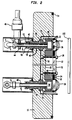
- FIG. 1 A preferred planar magnetron sputtering device is illustrated in FIG. 1, and is designated generally by reference numeral 10.
- the apparatus 10 includes a target 12 which may be composed of copper or some other metallic and non-magnetic material such as titanium or a titanium palladium alloy to prevent corrosive interaction between copper and titanium. It is possible to sputter other materials as well, such as ternary metals.
- the target 12 rests on a cooling block 14, which is in contact with a magnetic backing plate 15.
- the target 12, cooling block 14, and backing plate 15 are housed within a door assembly 16.
- a first surface 18 of the target 12 is provided with a first groove 19 and a second groove 21 (indicated in phantom).
- a first inner pole piece 20 and a second outer pole piece 22 fit within the grooves provided in a first surface 18 of the target 12.
- the inner pole piece 20 and outer pole piece 22 contact a rim of a first, inner magnet 24 and that of a second, outer magnet 26, respectively.
- the target 12 is brought into firm abutment with the cooling block 14 and retained thereon by means of screws 28 passing through the target 12.
- the door assembly 16 with the target 12 and magnets 24 and 26 is placed into an evacuable sputtering chamber (not shown) in opposed relationship to a substrate 100 mounted therein.
- a sputtering area 60 is defined within the sputtering chamber between the substrate and an opposite second surface 32 of the target 12.
- the sputtering apparatus 10 includes permanent inner magnet 24 and outer magnet 26, which are preferably ceramic magnets, such as barium nitrite.
- the inner magnet 24 may be a straight bar magnet, or as shown in the preferred embodiment, the magnet 24 may be fabricated as a pair, separated by non-magnetic spacer 25, composed preferably of aluminum, to facilitate central mounting of the target 12.
- the outer magnet 26 is constructed in a box-like configuration to surround the inner magnet 24. In the preferred embodiment, it is composed of a plurality of straight magnets in an octagonal shape in order for the magnet sections to remain substantially equidistant from the inner magnet 24.
- the inner magnet 24 is located in a central opening in the cooling block 14, and the outer magnet 26 surrounds the block 14.
- the top surface of the block 14 is substantially coplanar with the top rims of the inner magnet 24 and outer magnet 26.
- the permanent magnets 24 and 26 are oppositely magnetically oriented such that the pole of the inner magnet 24 in contact with the inner pole piece 20 is of the opposite polarity of the pole of the outer magnet 26 in contact with the outer pole piece 22.
- magnetic lines of force are provided which emerge from one of the magnets, pass through the target 12 and subsequently return through the target 12 to the other magnet, forming an arch 30.
- the magnetic backing plate 15 is in contact with the magnets 24 and 26, and completes the magnetic circuit path 31.
- the backing plate may be composed of a non-magnetic, magnetizable material such as soft iron, and it may be plated with nickel to prevent corrosion.
- the substantially concentric configuration of the inner magnet 24 and outer magnet 26 forms a continuous series of arched magnetic lines of force which extend in the form of a closed tunnel-like path between the inner magnet 24 and outer magnet 26.
- Inner pole piece 20 and outer pole piece 22 are provided in order to move the magnetic flux closer to the upper surface 32 of the target 12.
- the pole pieces 20 and 22 are composed of a non-magnetic, magnetizable material, such as soft iron or cold-rolled steel, which are effective in conducting the magnetic flux.
- the pole pieces 20 and 22 are configured with substantially the same planform shape as the permanent magnets 24 and 26 and are placed on the rim of the magnets.
- the first surface 18 of the target 12 is milled in the planform shape of the pole pieces 20 and 22 to a depth nominally exceeding the height of the pole pieces. This milling permits the pole pieces 20 and 22 to be embedded in the target 12.
- the pole pieces 20 and 22 act as extensions of the poles of the underlying magnets 24 and 26, respectively, and therefore have opposite polarity from each other.
- the magnetic flux lines are brought approximately parallel to the surface 32, and the magnetic field strength increases substantially to nearly maximum strength.
- This increase in magnetic field strength permits the sputtering apparatus 10 to be operated at lower voltages and lower pressures. Uniformity of deposited film could be controlled on sputtered substrates by varying the size and shape of the pole pieces 20 and 22.
- the cooling block 14 both provides temperature regulation of the target 12 as well as serving as conductor means for connecting the target 12 to a source of negative electrical potential. Milling the first surface 18 of the target 12 to a depth that exceeds the height of the pole pieces 20 and 22 to create an allowance therebetween permits the target 12 to be in a tight compressive fit with the cooling block 14 in order to provide an effective interface for target cooling and for electrical conductivity.
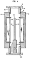
- the cooling block 14 has a lower channel section 34 having a substantially U-shaped cross-section, as seen in FIG. 2, and a ring-shaped planform, as seen in FIG. 1.
- the cooling block 14 also includes a cover plate 36, having a ring-shaped planform and fitting over the cooling block channel section 34, thereby forming a conduit 38 in which a coolant, such as water, may circulate.
- a coolant such as water
- the cross-sectional area of conduit 38 is maximized in the space between the inner magnet 24 and the outer magnet 26 in order to most effectively cool the target 12.
- a cooling water input tube 40 constructed of a conductive material such as stainless steel, extends from a cooling water source (not shown) into an aperture provided in the lower surface of the channel section 34.
- Coolant passes through the conduit 38 to cool the target 12, and is returned for re-cooling through a return tube 42 extending from another aperture in the channel section 34.
- the cooling block 14, and more particularly the channel section 34 is in contact with the backing plate 15, which assists in temperature regulation of the backing plate 15, as well as the magnets 24 and 26.
- High voltage is applied to the cooling block 14 during the operation of the sputtering apparatus 10 by connecting an electrical collar 44 on a high voltage cable 46 to a portion of either the cooling input tube 40 or the return tube 42. Since the cooling block 14 and cooling tubes 40 and 42 are of a conductive material, these components conduct a negative potential to the target 12.
- the sputtering apparatus 10, particularly the door assembly 16 is electrically grounded with respect to the cooling block 14 and target 12.
- the door assembly 16 is isolated from the cooling tubes 40 and 42 by insulative sleeves 48 composed of a material such as teflon, and by insulative O-rings 49.
- the insulative sleeves 48 may be fabricated in separate sections to improve isolation.
- sleeves 48 may consist of a first sleeve section 56 having a threaded portion and inserted in backing plate 15, a second sleeve section 58 also provided with threads and inserted in door assembly 16, and an insulating collar 60 and an O-ring 62 surrounding the water tubes 40 and 42 and providing a vacuum seal between the sputtering chamber and the outside atmosphere.
- An electric field is created substantially perpendicular to the upper surface 32 of the target 12.
- Ceramic spacers 50 provide support for the cooling block 14, target 12, and backing plate 15. The height of the spacers 50 is optimized to prevent plasma from forming between the backing plate 15 and door assembly 16 in order to inhibit sputtering of these components which would contaminate the film being deposited onto the substrate 100.
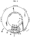
- the sputtering apparatus 10 may be operated in an evacuable chamber, together with the substrate 100 or piece part to be coated.
- the sputtering apparatus 10 and substrate 100 are capable of being oriented in a horizontal configuration such that substrate materials may be systematically conveyed beneath the target 12 for enhanced productivity.
- a vertical orientation offers several advantages over the horizontal orientation. By orientating the plane of the target surface 32 vertically, as shown in FIG. 2, target material ordinarily flaking off the target 12 would fall to the bottom of the chamber and not onto the substrate 100 itself. Furthermore, the vertical orientation relieves some stress on the cooling tubes 40 and 42.
- Sputtering chamber 200 may be constructed, for example, in a substantially cylindrical configuration consisting of an outer cylindrical wall member 202, an inner cylindrical wall member 204, a horizontal cover plate 206, and a horizontal base plate 208.
- Door assemblies 16 with targets 12 mounted therein as described above are mounted within rectangular apertures in the wall members 202 and 204 with annular seals 54 to prevent loss of pressure or contamination of sputtering process.
- the sputtering gas mixture is introduced into the sputtering chamber through a port (not shown), and a vacuum is provided in the sputtering chamber 200 by means well known in the art.
- a rotatable carousel 210 comprises a series of upstanding circumferentially spaced support posts 212 fixedly secured at lower ends thereof.
- Each support port 212 has a guideway assembly 214 such as inner and outer plates separated by an intermediate plate of reduced width, to define substrate holder edge-receiving guideways 216.
- a pair of planar substrates 100 are loaded in a rectangular frame-type holder or "tray" 218.
- the substrates 100 may be conveyed in a carousel fashion in front of the individual targets 12.
- a vacuum load lock (not shown) could be provided to remove sputtered substrates and insert new substrates while maintaining the very low pressure conditions.
Landscapes
- Chemical & Material Sciences (AREA)
- Engineering & Computer Science (AREA)
- Physics & Mathematics (AREA)
- Plasma & Fusion (AREA)
- Analytical Chemistry (AREA)
- Chemical Kinetics & Catalysis (AREA)
- Materials Engineering (AREA)
- Mechanical Engineering (AREA)
- Metallurgy (AREA)
- Organic Chemistry (AREA)
- Physical Vapour Deposition (AREA)
Applications Claiming Priority (2)
| Application Number | Priority Date | Filing Date | Title |
|---|---|---|---|
| US08/346,810 US5441614A (en) | 1994-11-30 | 1994-11-30 | Method and apparatus for planar magnetron sputtering |
| US346810 | 1994-11-30 |
Publications (1)
| Publication Number | Publication Date |
|---|---|
| EP0715336A2 true EP0715336A2 (de) | 1996-06-05 |
Family
ID=23361139
Family Applications (1)
| Application Number | Title | Priority Date | Filing Date |
|---|---|---|---|
| EP95308332A Withdrawn EP0715336A2 (de) | 1994-11-30 | 1995-11-21 | Verfahren und Vorrichtung zur Planar-Magnetron-Zerstäubung |
Country Status (5)
| Country | Link |
|---|---|
| US (1) | US5441614A (de) |
| EP (1) | EP0715336A2 (de) |
| JP (1) | JPH08209343A (de) |
| KR (1) | KR960019428A (de) |
| CN (1) | CN1130215A (de) |
Families Citing this family (11)
| Publication number | Priority date | Publication date | Assignee | Title |
|---|---|---|---|---|
| US5985115A (en) * | 1997-04-11 | 1999-11-16 | Novellus Systems, Inc. | Internally cooled target assembly for magnetron sputtering |
| CN1109127C (zh) * | 1998-10-09 | 2003-05-21 | 北京振涛国际钛金技术有限公司 | 非平衡平面磁控溅射阴极及其镀膜装置 |
| US6306265B1 (en) * | 1999-02-12 | 2001-10-23 | Applied Materials, Inc. | High-density plasma for ionized metal deposition capable of exciting a plasma wave |
| US6299740B1 (en) | 2000-01-19 | 2001-10-09 | Veeco Instrument, Inc. | Sputtering assembly and target therefor |
| EP1835524A1 (de) * | 2006-03-16 | 2007-09-19 | Sulzer Metco AG | Befestigungsvorrichtung für eine Sputterquelle |
| JP5265149B2 (ja) | 2006-07-21 | 2013-08-14 | アプライド マテリアルズ インコーポレイテッド | マルチカソード設計用冷却暗部シールド |
| CN102234776A (zh) * | 2010-04-22 | 2011-11-09 | 鸿富锦精密工业(深圳)有限公司 | 磁控溅镀装置 |
| TW201144462A (en) * | 2010-06-10 | 2011-12-16 | Hon Hai Prec Ind Co Ltd | Coating device |
| RU198710U1 (ru) * | 2020-02-10 | 2020-07-23 | Федеральное государственное бюджетное учреждение науки "Дагестанский федеральный исследовательский центр Российской академии наук" | Распылительный магнетрон |
| KR102722451B1 (ko) * | 2021-10-27 | 2024-10-24 | 한국핵융합에너지연구원 | E×b 힘을 이용한 플라즈마 가속장치 |
| CN114481072B (zh) * | 2022-02-16 | 2023-10-13 | 青岛科技大学 | 一种旋转式中间预热磁控溅射靶装置 |
Citations (1)
| Publication number | Priority date | Publication date | Assignee | Title |
|---|---|---|---|---|
| US5262028A (en) | 1992-06-01 | 1993-11-16 | Sierra Applied Sciences, Inc. | Planar magnetron sputtering magnet assembly |
Family Cites Families (12)
| Publication number | Priority date | Publication date | Assignee | Title |
|---|---|---|---|---|
| US3878085A (en) * | 1973-07-05 | 1975-04-15 | Sloan Technology Corp | Cathode sputtering apparatus |
| US4407708A (en) * | 1981-08-06 | 1983-10-04 | Eaton Corporation | Method for operating a magnetron sputtering apparatus |
| US4486289A (en) * | 1982-02-05 | 1984-12-04 | University Of British Columbia, Canada | Planar magnetron sputtering device |
| US4434042A (en) * | 1982-03-01 | 1984-02-28 | The Board Of Trustees Of The Leland Stanford Junior University | Planar magnetron sputtering apparatus |
| US4606802A (en) * | 1983-12-21 | 1986-08-19 | Hitachi, Ltd. | Planar magnetron sputtering with modified field configuration |
| DE3624150C2 (de) * | 1986-07-17 | 1994-02-24 | Leybold Ag | Zerstäubungskatode nach dem Magnetronprinzip |
| US5317006A (en) * | 1989-06-15 | 1994-05-31 | Microelectronics And Computer Technology Corporation | Cylindrical magnetron sputtering system |
| DE3929695C2 (de) * | 1989-09-07 | 1996-12-19 | Leybold Ag | Vorrichtung zum Beschichten eines Substrats |
| DE4135939A1 (de) * | 1991-10-31 | 1993-05-06 | Leybold Ag, 6450 Hanau, De | Zerstaeubungskathode |
| US5277779A (en) * | 1992-04-14 | 1994-01-11 | Henshaw William F | Rectangular cavity magnetron sputtering vapor source |
| US5282947A (en) * | 1992-08-13 | 1994-02-01 | Vlsi Technology, Inc. | Magnet assembly for enhanced sputter target erosion |
| US5286361A (en) * | 1992-10-19 | 1994-02-15 | Regents Of The University Of California | Magnetically attached sputter targets |
-
1994
- 1994-11-30 US US08/346,810 patent/US5441614A/en not_active Expired - Lifetime
-
1995
- 1995-11-21 EP EP95308332A patent/EP0715336A2/de not_active Withdrawn
- 1995-11-27 CN CN95120274A patent/CN1130215A/zh active Pending
- 1995-11-29 KR KR1019950044787A patent/KR960019428A/ko not_active Abandoned
- 1995-11-30 JP JP7311470A patent/JPH08209343A/ja not_active Withdrawn
Patent Citations (1)
| Publication number | Priority date | Publication date | Assignee | Title |
|---|---|---|---|---|
| US5262028A (en) | 1992-06-01 | 1993-11-16 | Sierra Applied Sciences, Inc. | Planar magnetron sputtering magnet assembly |
Also Published As
| Publication number | Publication date |
|---|---|
| CN1130215A (zh) | 1996-09-04 |
| KR960019428A (ko) | 1996-06-17 |
| JPH08209343A (ja) | 1996-08-13 |
| US5441614A (en) | 1995-08-15 |
Similar Documents
| Publication | Publication Date | Title |
|---|---|---|
| US4842703A (en) | Magnetron cathode and method for sputter coating | |
| US6254745B1 (en) | Ionized physical vapor deposition method and apparatus with magnetic bucket and concentric plasma and material source | |
| US6197165B1 (en) | Method and apparatus for ionized physical vapor deposition | |
| EP0051635B1 (de) | Sputter target und Vorrichtung zum Beschichten mittels Glimmentladung | |
| US4013532A (en) | Method for coating a substrate | |
| EP1489643B1 (de) | Verfahren und Vorrichtung zur ionisierten physikalischen Dampfabscheidung | |
| US4992153A (en) | Sputter-CVD process for at least partially coating a workpiece | |
| US3956093A (en) | Planar magnetron sputtering method and apparatus | |
| KR890004880B1 (ko) | 스퍼터링 방법 및 장치 | |
| US5772858A (en) | Method and apparatus for cleaning a target in a sputtering source | |
| US4810347A (en) | Penning type cathode for sputter coating | |
| US4414086A (en) | Magnetic targets for use in sputter coating apparatus | |
| US5490910A (en) | Circularly symmetric sputtering apparatus with hollow-cathode plasma devices | |
| US6238537B1 (en) | Ion assisted deposition source | |
| EP1390964A1 (de) | Dipol-ionenquelle | |
| US5441614A (en) | Method and apparatus for planar magnetron sputtering | |
| US4622122A (en) | Planar magnetron cathode target assembly | |
| KR20210089740A (ko) | Pvd 스퍼터링 증착 챔버의 경사형 마그네트론 | |
| WO2001029874A1 (en) | Planar magnetron sputtering apparatus | |
| EP0084971B2 (de) | Verfahren zur reaktiven vorgespannten Zerstäubung | |
| EP0544831B1 (de) | Zerstäubungsvorrichtung und -verfahren zur verbesserung der gleichmässigen ionenflussverteilung auf einem substrat | |
| EP0162643B1 (de) | Zerstäubungs-Beschichtungs-Quelle mit mehreren ringförmigen Auftreffplatten | |
| US11615947B2 (en) | Systems and methods for an improved magnetron electromagnetic assembly | |
| JPS62167878A (ja) | Ecrスパツタ装置 | |
| WO1992004483A1 (en) | Method of enhancing the performance of a magnetron sputtering target |
Legal Events
| Date | Code | Title | Description |
|---|---|---|---|
| PUAI | Public reference made under article 153(3) epc to a published international application that has entered the european phase |
Free format text: ORIGINAL CODE: 0009012 |
|
| AK | Designated contracting states |
Kind code of ref document: A2 Designated state(s): DE ES FR GB IT NL |
|
| STAA | Information on the status of an ep patent application or granted ep patent |
Free format text: STATUS: THE APPLICATION HAS BEEN WITHDRAWN |
|
| 18W | Application withdrawn |
Withdrawal date: 19971201 |