EP0715095B1 - Einrichtung zur Senkung von Drehmomentschwankungen in Antriebsgeräten - Google Patents
Einrichtung zur Senkung von Drehmomentschwankungen in Antriebsgeräten Download PDFInfo
- Publication number
- EP0715095B1 EP0715095B1 EP95203292A EP95203292A EP0715095B1 EP 0715095 B1 EP0715095 B1 EP 0715095B1 EP 95203292 A EP95203292 A EP 95203292A EP 95203292 A EP95203292 A EP 95203292A EP 0715095 B1 EP0715095 B1 EP 0715095B1
- Authority
- EP
- European Patent Office
- Prior art keywords
- drive shaft
- gear
- driven
- torque
- torque variations
- Prior art date
- Legal status (The legal status is an assumption and is not a legal conclusion. Google has not performed a legal analysis and makes no representation as to the accuracy of the status listed.)
- Expired - Lifetime
Links
- 230000005540 biological transmission Effects 0.000 claims description 8
- 238000007789 sealing Methods 0.000 claims description 6
- 230000033001 locomotion Effects 0.000 claims description 5
- 230000002441 reversible effect Effects 0.000 claims description 3
- 230000007246 mechanism Effects 0.000 description 11
- 230000006835 compression Effects 0.000 description 4
- 238000007906 compression Methods 0.000 description 4
- 230000004048 modification Effects 0.000 description 4
- 238000012986 modification Methods 0.000 description 4
- 238000010276 construction Methods 0.000 description 3
- 230000000881 depressing effect Effects 0.000 description 3
- 230000000452 restraining effect Effects 0.000 description 3
- 230000003247 decreasing effect Effects 0.000 description 2
- 230000000694 effects Effects 0.000 description 2
- 230000003292 diminished effect Effects 0.000 description 1
- 238000000034 method Methods 0.000 description 1
- 239000008267 milk Substances 0.000 description 1
- 210000004080 milk Anatomy 0.000 description 1
- 235000013336 milk Nutrition 0.000 description 1
- 238000004806 packaging method and process Methods 0.000 description 1
Images


Classifications
-
- F—MECHANICAL ENGINEERING; LIGHTING; HEATING; WEAPONS; BLASTING
- F16—ENGINEERING ELEMENTS AND UNITS; GENERAL MEASURES FOR PRODUCING AND MAINTAINING EFFECTIVE FUNCTIONING OF MACHINES OR INSTALLATIONS; THERMAL INSULATION IN GENERAL
- F16H—GEARING
- F16H33/00—Gearings based on repeated accumulation and delivery of energy
- F16H33/02—Rotary transmissions with mechanical accumulators, e.g. weights, springs, intermittently-connected flywheels
-
- F—MECHANICAL ENGINEERING; LIGHTING; HEATING; WEAPONS; BLASTING
- F16—ENGINEERING ELEMENTS AND UNITS; GENERAL MEASURES FOR PRODUCING AND MAINTAINING EFFECTIVE FUNCTIONING OF MACHINES OR INSTALLATIONS; THERMAL INSULATION IN GENERAL
- F16F—SPRINGS; SHOCK-ABSORBERS; MEANS FOR DAMPING VIBRATION
- F16F15/00—Suppression of vibrations in systems; Means or arrangements for avoiding or reducing out-of-balance forces, e.g. due to motion
- F16F15/02—Suppression of vibrations of non-rotating, e.g. reciprocating systems; Suppression of vibrations of rotating systems by use of members not moving with the rotating systems
- F16F15/04—Suppression of vibrations of non-rotating, e.g. reciprocating systems; Suppression of vibrations of rotating systems by use of members not moving with the rotating systems using elastic means
- F16F15/043—Suppression of vibrations of non-rotating, e.g. reciprocating systems; Suppression of vibrations of rotating systems by use of members not moving with the rotating systems using elastic means acting on a cam follower
-
- F—MECHANICAL ENGINEERING; LIGHTING; HEATING; WEAPONS; BLASTING
- F16—ENGINEERING ELEMENTS AND UNITS; GENERAL MEASURES FOR PRODUCING AND MAINTAINING EFFECTIVE FUNCTIONING OF MACHINES OR INSTALLATIONS; THERMAL INSULATION IN GENERAL
- F16H—GEARING
- F16H25/00—Gearings comprising primarily only cams, cam-followers and screw-and-nut mechanisms
- F16H25/16—Gearings comprising primarily only cams, cam-followers and screw-and-nut mechanisms for interconverting rotary motion and oscillating motion
-
- B—PERFORMING OPERATIONS; TRANSPORTING
- B29—WORKING OF PLASTICS; WORKING OF SUBSTANCES IN A PLASTIC STATE IN GENERAL
- B29C—SHAPING OR JOINING OF PLASTICS; SHAPING OF MATERIAL IN A PLASTIC STATE, NOT OTHERWISE PROVIDED FOR; AFTER-TREATMENT OF THE SHAPED PRODUCTS, e.g. REPAIRING
- B29C66/00—General aspects of processes or apparatus for joining preformed parts
- B29C66/01—General aspects dealing with the joint area or with the area to be joined
- B29C66/05—Particular design of joint configurations
- B29C66/10—Particular design of joint configurations particular design of the joint cross-sections
- B29C66/11—Joint cross-sections comprising a single joint-segment, i.e. one of the parts to be joined comprising a single joint-segment in the joint cross-section
- B29C66/112—Single lapped joints
- B29C66/1122—Single lap to lap joints, i.e. overlap joints
-
- B—PERFORMING OPERATIONS; TRANSPORTING
- B29—WORKING OF PLASTICS; WORKING OF SUBSTANCES IN A PLASTIC STATE IN GENERAL
- B29C—SHAPING OR JOINING OF PLASTICS; SHAPING OF MATERIAL IN A PLASTIC STATE, NOT OTHERWISE PROVIDED FOR; AFTER-TREATMENT OF THE SHAPED PRODUCTS, e.g. REPAIRING
- B29C66/00—General aspects of processes or apparatus for joining preformed parts
- B29C66/40—General aspects of joining substantially flat articles, e.g. plates, sheets or web-like materials; Making flat seams in tubular or hollow articles; Joining single elements to substantially flat surfaces
- B29C66/41—Joining substantially flat articles ; Making flat seams in tubular or hollow articles
- B29C66/43—Joining a relatively small portion of the surface of said articles
- B29C66/431—Joining the articles to themselves
- B29C66/4312—Joining the articles to themselves for making flat seams in tubular or hollow articles, e.g. transversal seams
-
- B—PERFORMING OPERATIONS; TRANSPORTING
- B29—WORKING OF PLASTICS; WORKING OF SUBSTANCES IN A PLASTIC STATE IN GENERAL
- B29C—SHAPING OR JOINING OF PLASTICS; SHAPING OF MATERIAL IN A PLASTIC STATE, NOT OTHERWISE PROVIDED FOR; AFTER-TREATMENT OF THE SHAPED PRODUCTS, e.g. REPAIRING
- B29C66/00—General aspects of processes or apparatus for joining preformed parts
- B29C66/80—General aspects of machine operations or constructions and parts thereof
- B29C66/82—Pressure application arrangements, e.g. transmission or actuating mechanisms for joining tools or clamps
- B29C66/822—Transmission mechanisms
- B29C66/8226—Cam mechanisms; Wedges; Eccentric mechanisms
-
- B—PERFORMING OPERATIONS; TRANSPORTING
- B29—WORKING OF PLASTICS; WORKING OF SUBSTANCES IN A PLASTIC STATE IN GENERAL
- B29C—SHAPING OR JOINING OF PLASTICS; SHAPING OF MATERIAL IN A PLASTIC STATE, NOT OTHERWISE PROVIDED FOR; AFTER-TREATMENT OF THE SHAPED PRODUCTS, e.g. REPAIRING
- B29C66/00—General aspects of processes or apparatus for joining preformed parts
- B29C66/80—General aspects of machine operations or constructions and parts thereof
- B29C66/83—General aspects of machine operations or constructions and parts thereof characterised by the movement of the joining or pressing tools
- B29C66/834—General aspects of machine operations or constructions and parts thereof characterised by the movement of the joining or pressing tools moving with the parts to be joined
- B29C66/8351—Jaws mounted on rollers, cylinders, drums, bands, belts or chains; Flying jaws
- B29C66/83541—Jaws mounted on rollers, cylinders, drums, bands, belts or chains; Flying jaws flying jaws, e.g. jaws mounted on crank mechanisms or following a hand over hand movement
- B29C66/83543—Jaws mounted on rollers, cylinders, drums, bands, belts or chains; Flying jaws flying jaws, e.g. jaws mounted on crank mechanisms or following a hand over hand movement cooperating flying jaws
-
- B—PERFORMING OPERATIONS; TRANSPORTING
- B29—WORKING OF PLASTICS; WORKING OF SUBSTANCES IN A PLASTIC STATE IN GENERAL
- B29C—SHAPING OR JOINING OF PLASTICS; SHAPING OF MATERIAL IN A PLASTIC STATE, NOT OTHERWISE PROVIDED FOR; AFTER-TREATMENT OF THE SHAPED PRODUCTS, e.g. REPAIRING
- B29C66/00—General aspects of processes or apparatus for joining preformed parts
- B29C66/80—General aspects of machine operations or constructions and parts thereof
- B29C66/84—Specific machine types or machines suitable for specific applications
- B29C66/849—Packaging machines
-
- B—PERFORMING OPERATIONS; TRANSPORTING
- B65—CONVEYING; PACKING; STORING; HANDLING THIN OR FILAMENTARY MATERIAL
- B65B—MACHINES, APPARATUS OR DEVICES FOR, OR METHODS OF, PACKAGING ARTICLES OR MATERIALS; UNPACKING
- B65B51/00—Devices for, or methods of, sealing or securing package folds or closures; Devices for gathering or twisting wrappers, or necks of bags
- B65B51/10—Applying or generating heat or pressure or combinations thereof
- B65B51/26—Devices specially adapted for producing transverse or longitudinal seams in webs or tubes
- B65B51/30—Devices, e.g. jaws, for applying pressure and heat, e.g. for subdividing filled tubes
-
- Y—GENERAL TAGGING OF NEW TECHNOLOGICAL DEVELOPMENTS; GENERAL TAGGING OF CROSS-SECTIONAL TECHNOLOGIES SPANNING OVER SEVERAL SECTIONS OF THE IPC; TECHNICAL SUBJECTS COVERED BY FORMER USPC CROSS-REFERENCE ART COLLECTIONS [XRACs] AND DIGESTS
- Y10—TECHNICAL SUBJECTS COVERED BY FORMER USPC
- Y10T—TECHNICAL SUBJECTS COVERED BY FORMER US CLASSIFICATION
- Y10T74/00—Machine element or mechanism
- Y10T74/18—Mechanical movements
- Y10T74/18056—Rotary to or from reciprocating or oscillating
- Y10T74/18144—Overcoming dead center
-
- Y—GENERAL TAGGING OF NEW TECHNOLOGICAL DEVELOPMENTS; GENERAL TAGGING OF CROSS-SECTIONAL TECHNOLOGIES SPANNING OVER SEVERAL SECTIONS OF THE IPC; TECHNICAL SUBJECTS COVERED BY FORMER USPC CROSS-REFERENCE ART COLLECTIONS [XRACs] AND DIGESTS
- Y10—TECHNICAL SUBJECTS COVERED BY FORMER USPC
- Y10T—TECHNICAL SUBJECTS COVERED BY FORMER US CLASSIFICATION
- Y10T74/00—Machine element or mechanism
- Y10T74/18—Mechanical movements
- Y10T74/18056—Rotary to or from reciprocating or oscillating
- Y10T74/18248—Crank and slide
-
- Y—GENERAL TAGGING OF NEW TECHNOLOGICAL DEVELOPMENTS; GENERAL TAGGING OF CROSS-SECTIONAL TECHNOLOGIES SPANNING OVER SEVERAL SECTIONS OF THE IPC; TECHNICAL SUBJECTS COVERED BY FORMER USPC CROSS-REFERENCE ART COLLECTIONS [XRACs] AND DIGESTS
- Y10—TECHNICAL SUBJECTS COVERED BY FORMER USPC
- Y10T—TECHNICAL SUBJECTS COVERED BY FORMER US CLASSIFICATION
- Y10T74/00—Machine element or mechanism
- Y10T74/18—Mechanical movements
- Y10T74/18056—Rotary to or from reciprocating or oscillating
- Y10T74/1828—Cam, lever, and slide
-
- Y—GENERAL TAGGING OF NEW TECHNOLOGICAL DEVELOPMENTS; GENERAL TAGGING OF CROSS-SECTIONAL TECHNOLOGIES SPANNING OVER SEVERAL SECTIONS OF THE IPC; TECHNICAL SUBJECTS COVERED BY FORMER USPC CROSS-REFERENCE ART COLLECTIONS [XRACs] AND DIGESTS
- Y10—TECHNICAL SUBJECTS COVERED BY FORMER USPC
- Y10T—TECHNICAL SUBJECTS COVERED BY FORMER US CLASSIFICATION
- Y10T74/00—Machine element or mechanism
- Y10T74/21—Elements
- Y10T74/2142—Pitmans and connecting rods
- Y10T74/2154—Counterbalanced
- Y10T74/2158—Spring
Definitions
- the present invention relates to a device for reducing variations in torque for use in drive apparatus, for example, for driving lift units equipped with container forming jaws and included in a container forming machine which is adapted to make a content-filled vertical tube into baglike containers by sealing the tube at a spacing corresponding to the length of the container and cutting the sealed portions.
- the disclosed apparatus comprises first and second hydraulic cylinders which are connected together in series.
- the first hydraulic cylinder has a piston rod connected to a lift unit
- the second hydraulic cylinder has a piston rod connected to the frame of the device.
- the first cylinder is operated so as to be in balance with the weight of the lift unit.
- the second cylinder is operated for raising the lift unit.
- the apparatus described requires the pair of first and second hydraulic cylinders for one lift unit and therefore necessitates pairs of first and second hydraulic cylinders for a plurality of lift units.
- the apparatus has the problem of being complex in construction and costly.
- An object of the present invention is to overcome the above problem and provide a device for reducing torque variations which is simple in construction and less costly for use in drive apparatus.
- the present invention provides a drive device comprising elastic means and transmission means for transmitting an elastic force of the elastic means to the drive shaft as a rotational torque
- the transmission means comprises a main gear fixed to the drive shaft, a driven gear coupled to the main gear for power transmission therebetween, a driven shaft having the driven gear fixed thereto, and an arm fixed to the driven shaft and having a forward end coupled to the elastic means so that the elastic force of the elastic means can act on said forward end of the arm and whereby the number of cycles of torque variations involved in one turn of rotation of the drive shaft is n (integer), the gear ratio of the main gear to the driven gear is n:1.
- the elastic force of the elastic means acts on the drive shaft as a positive torque and a negative torque.
- the speed of rotation of the drive gear is transmitted to the drive shaft on being increased and decreased in corresponding relation with the number of torque variation cycles, so that the driven shaft acts to offset the combined torque variations which are repeated periodically. This effectively reduces the torque variations of the drive shaft by a simple and inexpensive mechanism.
- the lift units are two in number, and the torque of the drive shaft is adapted to reach a positive maximum value and a negative maximum value each twice alternately during the rotation of the drive shaft through 360 degrees for one cycle
- the transmission means comprising a main gear fixed to the drive shaft, a driven gear coupled to the main gear for power transmission, a driven shaft having the driven gear fixed thereto, and an arm fixed to the driven shaft and to be acted on by the elastic force of the elastic means so that the torque of the driven shaft reaches a positive maximum value and a negative maximum value each once during the rotation of the driven shaft through 360 degrees for one cycle, the gear ratio of the main gear to the driven gear being 2:1, the drive shaft and the driven shaft being so timed as to be approximately reverse in the phase of their positive and negative torque maximum values.
- the positive and negative torque maximum values of the drive shaft are then offset respectively by the negative and positive torque maximum values of the driven shaft. This reduces the torque variations of the drive shaft very effectively.
- the 360-degree cycle of the drive shaft includes 90-degree rotation assigned to an ascent stroke of the lift unit, with the remaining 270-degree rotation assigned to a descent stroke of the lift unit.
- the variations in the torque acting on the drive shaft are then approximate to a sine curve and can therefore be reduced readily.
- the main gear and the driven gear are each a spur gear and in mesh with each other.
- the main gear and the driven gear may each be a sprocket, with a chain or toothed belt reeved around the main gear and the driven gear.
- the lift unit is equipped with container forming jaws for making a content-filled vertical tube into baglike containers by sealing the tube at a spacing corresponding to the length of the container and cutting the sealed portions, the drive shaft has fixed thereto cams equal in number to the number of lift units, and the cam is provided with a cam follower connected to the lift unit.
- mechanism 1045 has been described a mechanism wherein a shaft is driven by a piston-cilinder assembly via a toothed rack and pinion. On said shaft has been mounted a cam co-operating with a pivotable arm.
- front refers to the side toward the direction of arrow A in FIG. 1
- rear to the opposite side
- right and left are used for the device as it is seen from behind.
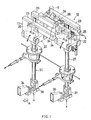
- a container forming apparatus comprises left and right jaw units 11, 12 for holding a content-filled heat-sealable tube T thereacross to form sealed portions having a width and cutting the sealed portions each at the midportion of the width, and a drive mechanism 13 for moving these jaw units 11, 12 alternately up and down in different directions as timed with each other with a stroke length corresponding to the length of the container to be made.
- the jaw units 11, 12 have the same construction although oriented in opposite directions transversely of the apparatus.
- the right jaw unit 12 only will be described below, and like parts of these units 11, 12 are designated by like reference numerals and will not be described repeatedly.
- the jaw unit 12 comprises a vertical rod 21 which is movable up and down and reversibly rotatable, a lift frame 22 movable up and down with the vertical rod 21 and mounted on the rod 21 so as to permit the reversible rotation thereof, a pair of front and rear pivotal arms 23 supported at their lower portions by the lift frame 22 so as to be movable respectively about a pair of horizontal axes parallel to each other, a pair of front and rear jaws 24 fixed to the upper portions of the respective pivotal arms 23 and opposed to each other, an arm opener 25 for pivotally moving the arms 23 between a closed position where the jaws 24 are close to each other and an opened position where the jaws are away from each other, and a press 26 for producing a sealing pressure between the jaws 24 by pulling the pivotal arms 23 toward each other at the closed position.
- the front jaw 24 is provided with a heater for heat sealing, and the rear jaw 24 with a cutter.
- the arm opener 25 closes the two pivotal arms 23 to position the jaws 24 close to each other, and the press 26 pulls the arms 23 toward each other to hold the tube T between the jaws 24 and produce a sealing pressure therebetween, whereby the tube T is sealed.
- the jaws 24 holding the tube T therebetween descend with the lift frame 22, thereby transporting the tube T by a length corresponding to one container.
- the cutter is actuated to cut the tube T.
- the press 26 is then brought out of pressing operation, whereupon the arm opener 25 opens the pivotal arms 23 to open the jaws 24 and release the tube T.
- the leading end portion of the tube corresponding to one container is separated from the other portion.
- the drive mechanism 13 comprises a horizontal drive shaft 31 extending transversely of the apparatus and disposed in the rear of the lower ends of the vertical rods 21 obliquely therebelow, a left jaw unit cam 32 and right jaw unit cam 33 fixed to the drive shaft 31, and an armlike cam follower 34 and similar cam follower 35 extending over the respective cams 32, 33.
- an arm opening cam is also fixed to the drive shaft 31.
- the cam follower 34 for the left jaw unit 11 has a front end connected to the lower end of the vertical rod 21 of the unit 11 by a connecting member 36.
- the cam follower 35 for the right jaw unit 12 has a front end connected to the lower end of the vertical rod 21 of the unit 12 by a connecting member 37.
- a main gear 41 is fixedly mounted on the drive shaft 31.
- Disposed in front of the drive shaft 31 is a horizontal driven shaft 42 extending transversely of the apparatus in parallel to the shaft 31.
- the driven shaft 42 fixedly carries a driven gear 43 meshing with the main gear 41.
- the gear ratio of the main gear 41 to the driven gear 43 is 2:1.
- An arm 44 is secured to the right end of the driven shaft 42 and has an outer end connected to the piston rod 46 of a hydraulic cylinder 45.
- One end of a pressurized air supply tube 47 is connected to the rod side of the cylinder 45.
- the other end of the supply tube 47 is connected to an unillustrated air tank, whereby pressurized air of constant pressure free of pressure variations is supplied to the hydraulic cylinder 45 for urging the piston rod 46 toward a retracted position at all times.
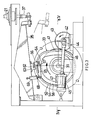
- the cams 32 and 33 have the same shape and are each in the form of a plate cam having an outer periphery serving as a cam contour face 51 or 52.
- the perimeter of the cam contour face 52 subtends 360 degrees and includes a 90-degree portion which is shown as an ascent range U in FIG. 3 and assigned to the ascent stroke of the lift frame 22, the remaining 270-degree portion being shown as a descent range D and assigned to the descent stroke of the lift frame 22.
- the ascent range U, as well as the descent range D, of the left jaw unit cam 32 is different from the corresponding range of the right jaw unit cam 33 by 180 degrees in phase.
- the cam 32 (33) is formed in its right side with an annular recessed portion 53 (54) close to the outer periphery thereof and having an inwardly facing periphery, which provides a guide face 55 (56) extending along the cam contour face 51 (52).
- the guide face 55 (56) is parallel to the cam contour face 51 (52) where the contour face is in the form of a circular arc but is slightly not parallel to the portion of the contour face 51 (52) which varies in curvature to make the fixed roller 62 and movable roller 67 to be described below identical in cam lift phase.
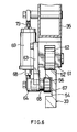
- the right jaw unit cam follower 35 is provided at a lengthwise intermediate portion thereof with a bifurcated bracket 61 extending downward from the follower.
- a fixed roller 62 bearing on the cam contour face 52 is mounted on the bracket 61.
- Fixed to the right side (shown as the left side in FIG. 6) of the bracket 61 is a lever suspending plate 63 extending downward therefrom and having a lower end opposed to the annular recessed portion 54 from the right side thereof.
- a horizontal guide sleeve 64 is secured to and projects rightward from the lower end of the suspending plate 63.
- a roller lever 65 extending rearward is disposed at the left end of the guide sleeve 64 and has at its front end a horizontal pivot 65 projecting rightward and rotatably fitted in the guide sleeve 64.
- a movable roller 67 bearing on the guide face 56 is mounted on the roller lever 65 as if projecting leftward therefrom.
- a vertical pull-up rod 68 has a lower end pivoted to the rear end of the roller lever 65.
- a vertical tubular spring housing 69 provided with a top wall has an upper end pivoted to the cam follower 35 and an open lower end with a male screw member 75 driven therein.
- the pull-up rod 68 has an upper portion extending into the spring housing 69 through the screw member 75.
- a retaining nut 74 is screwed on the screw member 75.
- the pull-up rod 68 is formed with a flange 71 at its upper end.
- a roller restraining compression spring 72 is provided between the screw member 75 and the flange 71.
- Spring holding bolts 73 for releasing the roller 67 extend through the top wall of the spring housing 69 in screw-thread engagement therewith.
- the compression spring 72 biases the pull-up rod 61 upward, thereby urging the roller lever 65 to pivotally move upward about the pivot 66. As a result, the fixed roller 62 is pressed against the cam contour face 52 and the movable roller 67 against the guide face 56.
- the left jaw unit cam follower 34 is also provided with a fixed roller 62, movable roller 67, etc.
- the rotational motion of the drive shaft 31 is converted by the two cams 32, 33 and cam followers 34, 35 into reciprocating motions, which are delivered respectively to the vertical rods 21 of the two jaw units 11, 12.
- the jaw unit 11 is lowered with their pivotal arms 23 closed, while the other jaw unit 12 is raised outside the closed pivotal arms 23 of the jaw unit 11, with their pivotal arms 23 opened.
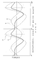
- the torque of the drive shaft 31 is great when raising the jaw units 11, 12, and is small when lowering the jaw units 11, 12. While the drive shaft 31 rotates through 360 degrees for one cycle, the drive torque reaches a maximum value and a minimum value each twice. These torque variations are represented by a curve P in FIG. 7.
- FIG. 3 shows the right jaw unit cam 33 as positioned at a border between the ascent range U and the descent range D and the arm 44 as directed rearward, with the piston rod 46 of the hydraulic cylinder 45 in a retracted limit position.
- the right jaw unit 12 is in its upper limit position.
- the right jaw unit cam 33 when rotated through 270 degrees from the position of FIG. 3, moves past the descent range D to reach another border between the descent range D and the ascent range U, bringing the right jaw unit 12 to its lower limit position.
- the driven shaft 42 is rotated through 540 degrees, i.e., one and a half turns. When the rotation of one and half turns is divided into three half turns, the torque of the drive shaft 31 is successively reduced, increased and reduced every half turn.
- the right jaw unit cam 33 is brought to the state of FIG. 3 when rotated through 90 degrees from the border between the descent range D and the ascent range U. More specifically, the cam 33 moves past the ascent range U and the descent range D, raising the right jaw unit 12 to its upper limit position. In the meantime, the drive shaft 42 is rotated through 180 degrees, turning the arm 44 from a forward to a rearward direction to retract the piston rod 46 of the cylinder 45 and consequently increasing the torque of the drive shaft 31.
- the left jaw unit 11 now reaches its upper limit position.
- the driven shaft 42 is rotated through 360 degrees, i.e., one turn. Accordingly, every time the driven shaft 42 makes a full rotation through 360 degrees, the torque of the drive shaft 31 is increased, whereby the variations in the torque of the shaft 31 are reduced, permitting use of a motor of decreased capacity for driving the drive shaft 31.
- the positive maximum value of the curve P conincides with the negative maximum value of the curve Q (the dot-and-dash line in FIG. 7).
- the curve P and the curve Q when combined, make a curve R, and the positive maximum value of the curve R is considerably lower than the positive maximum value of the curve P. This indicates that the torque variations are diminished.
- An equivalent effect is also available by making the zero point of the curve P coincide with that of the curve Q instead of making the positive maximum value of the curve P coincide with the negative maximum value of the curve Q.
- roller restraining compression spring 72 is compressed to cause the lever pull-up rod 68 to project from the spring housing 69 and release the fixed rollers 62 from the cam contour faces 51, 52 although the movable rollers 67 remain in contact with the guide faces 55, 56.
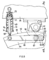
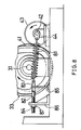
- FIG. 8 shows a modification wherein a coiled tension spring 81 is used.
- the tension spring 81 has a front end attached to the outer end of the arm 44 and a rear end attached to the front end of a spring force adjusting horizontal rod 82 extending longitudinally of the apparatus.
- the adjusting rod 82 has a cutout 83 in a front portion thereof and is in the form of a male screw 84 in the rear of the cutout.
- the cutout 83 has a vertical flat-surfaced bottom, against which a vertical retaining rod 85 bears.
- the male screw 84 has a rear end portion extending through a vertical support bracket 86 to project rearward beyond the bracket.
- a spring force adjusting nut 87 serving also as a stopper is screwed on the rear projecting portion of the male screw 84.
- the spring 81 With the rotation of the arm 44, the spring 81 stretches or contracts, giving a varying spring force.
- the elastic force to be applied to the outer end of the arm 44 therefore varies. Accordingly, the torque produced in the driven shaft 42 is represented by a curve S in FIG. 7, i.e., a slightly modified sine curve.
- a different roller lever 91 is used in place of the roller lever 65 included in the foregoing embodiment.
- the roller lever 91 has the movable roller 67 mounted on its front end and is supported by the pivot 66 at a portion thereof close to the lever front end.
- a vertical depressing rod 92 has a lower end pivoted to the rear end of the roller lever 91.
- a vertical tubular spring housing 93 provided with a top wall has an upper end pivoted to the cam follower 35 and an open lower end with a male screw member 97 driven therein.
- the depressing rod 92 has an upper portion extending into the spring housing 93 through the screw member 97.
- a retaining nut 98 is screwed on the screw member 97.
- the depressing rod 92 is formed with a flange 94 at its upper end.
- This modification differs from the foregoing embodiment in that a roller restraining compression spring 95 is provided between the top wall of the spring housing 93 and the flange 93, and that spring holding bolts 96 are screwed into the male screw member 97.
- Sprockets are usable as the main gear and the driven gear instead of spur gears.
- a chain or toothed belt is then reeved around the sprockets.
- the number of lift frames does not always correspond to the number of torque variation cycles.
- the number of torque variation cycles can be, for example, 1 or 3.
- the arm may be secured to the drive shaft, with the driven shaft omitted, or the arm may be secured to the driven shaft provided.
- the gear ratio of the main gear to the driven gear is then 1:1.
- the timing of the driven shaft relative to the drive shaft is variable as desired by altering the meshing phase of the two gears so as to achieve the highest effect to reduce the torque variations.
- the gear ratio of the main gear to the driven gear is n (integer) which is at least 3 and corresponds to the cycle number to 1.
- the present invention is applicable, for example, to packaging machines for milk packs of the gabled top type.
- the lift frame of the above embodiment is replaced by a lift unit comprising a filling piston of a filling device and a container lift.
- the interval between the two lift units to be moved up and down is not always 180 degrees but can be, for example, 150 degrees.
- lift units to which the present invention is applicable can be those comprising any mechanical element and having an up-and-down stroke.
Landscapes
- Engineering & Computer Science (AREA)
- General Engineering & Computer Science (AREA)
- Mechanical Engineering (AREA)
- Physics & Mathematics (AREA)
- Acoustics & Sound (AREA)
- Aviation & Aerospace Engineering (AREA)
- Transmission Devices (AREA)
Claims (8)
- Eine Einrichtung zur Senkung von Drehmomentschwankungen in Antriebsgeräten mit einer Antriebswelle, um zu bewirken, daß jede von wenigstens zwei Hebeeinheiten (22) einen Zyklus einer Aufwärts- und Abwärtsbewegung in einem bestimmten Intervall durch eine Rotationsumdrehung der Antriebswelle (31) ausführt, und einer Antriebseinrichtung mit einem elastischen Mittel und einem Übertragungsmittel, um eine elastische Kraft des elastischen Mittels (45, 46) auf die Antriebswelle (31) als ein Drehmoment zu übertragen, wobei das Übertragungsmittel wenigstens ein an der Antriebswelle (31) befestigtes Hauptzahnrad (41), ein angetriebenes Zahnrad (43), das mit dem Hauptzahnrad zur Leistungsübertragung zwischen ihnen gekuppelt ist, eine Antriebswelle (42), an der das angetriebene Zahnrad (43) befestigt ist, und einen Arm (44), der an der Antriebswelle (42) befestigt ist und an einem vorderen Ende mit dem elastischen Mittel (45, 46) gekuppelt ist, so daß die elastische Kraft des elastischen Mittels (45, 46) auf das vordere Ende des Arms (44) wirkt, aufweist, wobei, wenn die Zyklusanzahl von Drehmomentänderungen, die mit einer Rotationsdrehung der Antriebswelle (41) verbunden ist, n (integer) ist, das Übersetzungsverhältnis des Hauptrades (41) zu dem angetriebenen Zahnrad (43) n:1 ist.
- Eine Einrichtung zur Senkung von Drehmomentschwankungen wie in Anspruch 1 definiert, dadurch gekennzeichnet, daß die Hebeeinheiten (22) zwei in der Anzahl sind, das Drehmoment der Antriebswelle (31) geeignet ist, einen positiven Maximalwert und einen negativen Maximalwert jeweils zweimal im Wechsel während der Rotation der Antriebswelle (31) um 360° für einen Zyklus zu erreichen, das Drehmoment der Abtriebswelle (42) einen positiven Maximalwert und einen negativen Maximalwert jeweils einmal während der Drehung der Abtriebswelle (42) um 360° für einen Zyklus erreicht, das Übersetzungsverhältnis des Hauptzahnrades (41) zu dem angetriebenen Zahnrad (43) 2:1 ist und die Antriebswelle (31) und die Abtriebswelle (42) so getimed sind, daß sie etwa entgegengesetzt in der Phase ihrer positiven und negativen Maximaldrehmomentwerte sind.
- Eine Einrichtung zur Senkung von Drehmomentschwankungen wie in Anspruch 2 definiert, worin der 360°-Zyklus der Antriebswelle (31) eine 90°-Drehung umfaßt, die einem Aufwärtshub der Hebeeinheit (22) zugeordnet ist, wobei die verbleibende 270°-Drehung einem Absenkhub der Hebeeinheit (22) zugeordnet ist.
- Eine Einrichtung zur Senkung von Drehmomentschwankungen wie in irgendeinem der vorherigen Ansprüche definiert, dadurch gekennzeichnet, daß ein Hydraulikzylinder (45) eine Kolbenstange (46) hat, die mit dem vorderen Ende des Arms (44) verbunden ist.
- Eine Einrichtung zur Senkung von Drehmomentschwankungen wie in irgendeinem der vorherigen Ansprüche definiert, dadurch gekennzeichnet, daß eine Feder (81) zwischen dem vorderen Ende des Arms (44) und einem Stützelement angeordnet ist.
- Eine Einrichtung zur Senkung von Drehmomentschwankungen wie in irgendeinem der vorherigen Ansprüche definiert, dadurch gekennzeichnet, daß das Hauptzahnrad (41) und das angetriebene Zahnrad (43) jeweils Stirnräder sind und in kämmendem Eingriff miteinander stehen.
- Eine Einrichtung zur Senkung von Drehmomentschwankungen wie in irgendeinem der Ansprüche 1 bis 5 definiert, dadurch gekennzeichnet, daß das Hauptzahnrad (41) und das angetriebene Zahnrad (43) jeweils ein Kettenrad sind und eine Kette oder ein Zahnriemen um das Hauptzahnrad (41) und das angetriebene Zahnrad (43) läuft.
- Eine Einrichtung zur Senkung von Drehmomentschwankungen wie in irgendeinem der vorherigen Ansprüche definiert, dadurch gekennzeichnet, daß jede der Hebeeinheiten (22) mit Behälterformklauen (24) ausgerüstet ist, um einen mit einem Inhalt gefüllten vertikalen Schlauch zu beutelähnlichen Behältern zu machen, indem der Schlauch in einem Abstand, der der Länge des Behälters entspricht, verschlossen wird und die verschlossenen Abschnitte abgeschnitten werden, und daß an der Antriebswelle (31) Nocken (32, 33) in der gleichen Anzahl wie die Anzahl von Hebeeinheiten (22) befestigt sind, wobei die Nocken (32, 33) jeweils mit Nockenstößeln (34, 35) versehen sind, die mit den entsprechenden Hebeeinheiten (22) verbunden sind.
Applications Claiming Priority (4)
| Application Number | Priority Date | Filing Date | Title |
|---|---|---|---|
| JP298133/94 | 1994-12-01 | ||
| JP29813394 | 1994-12-01 | ||
| JP148989/95 | 1995-06-15 | ||
| JP14898995A JP3600941B2 (ja) | 1994-12-01 | 1995-06-15 | 駆動装置におけるトルク変動低減装置 |
Publications (3)
| Publication Number | Publication Date |
|---|---|
| EP0715095A2 EP0715095A2 (de) | 1996-06-05 |
| EP0715095A3 EP0715095A3 (de) | 1996-08-28 |
| EP0715095B1 true EP0715095B1 (de) | 1999-03-03 |
Family
ID=26479012
Family Applications (1)
| Application Number | Title | Priority Date | Filing Date |
|---|---|---|---|
| EP95203292A Expired - Lifetime EP0715095B1 (de) | 1994-12-01 | 1995-11-29 | Einrichtung zur Senkung von Drehmomentschwankungen in Antriebsgeräten |
Country Status (5)
| Country | Link |
|---|---|
| US (1) | US5813281A (de) |
| EP (1) | EP0715095B1 (de) |
| JP (1) | JP3600941B2 (de) |
| DE (1) | DE69508042T2 (de) |
| DK (1) | DK0715095T3 (de) |
Families Citing this family (5)
| Publication number | Priority date | Publication date | Assignee | Title |
|---|---|---|---|---|
| US6073516A (en) * | 1998-05-11 | 2000-06-13 | Riverwood International Corporation | Multi-function cam for a packaging machine |
| US6098478A (en) * | 1998-11-06 | 2000-08-08 | Emerson Electric Co. | Linear pick and place drive with adjustable stroke ranges |
| KR101066337B1 (ko) * | 2009-04-03 | 2011-09-20 | 윤태호 | 회전력 전달장치 |
| CN109279094B (zh) * | 2018-08-30 | 2020-06-26 | 嘉兴市豪艺家纺有限公司 | 一种灌装用物料盒传送装置 |
| CN111425549B (zh) * | 2020-04-22 | 2021-08-17 | 合肥康尔信电力系统有限公司 | 一种柴油发电机安装减震装置 |
Family Cites Families (12)
| Publication number | Priority date | Publication date | Assignee | Title |
|---|---|---|---|---|
| US377225A (en) * | 1888-01-31 | Pump-rod attachment | ||
| US1688484A (en) * | 1926-04-27 | 1928-10-23 | Anson Robinson | Pumping apparatus |
| US1913225A (en) * | 1932-09-24 | 1933-06-06 | John H Young | Deep well pumping mechanism |
| US3377882A (en) * | 1965-08-26 | 1968-04-16 | Pitney Bowes Inc | Mechanical energy storage system |
| US3449888A (en) * | 1965-09-15 | 1969-06-17 | Hayssen Mfg Co | Packaging machine |
| DE1263434B (de) * | 1966-09-02 | 1968-03-14 | Ibm Deutschland | Kurvengetriebe mit Drehmomentausgleich |
| US3413862A (en) * | 1967-04-18 | 1968-12-03 | Visi Trol Engineering Corp | Cam controlled actuator including intermittent torque means |
| SE416158B (sv) * | 1978-10-25 | 1980-12-01 | Tetra Pak Int | Anordning for kompensation av masskrafter vid ett maskinelement som medelst ett drivorgan och en kamkurva er forflyttbart mellan ett ovre och ett undre vendlege enligt ett bestemt, upprepat rorelsemonster |
| DD213404A1 (de) * | 1983-01-31 | 1984-09-12 | Nagema Veb K | Querverschliessvorrichtung |
| DE3714637A1 (de) * | 1987-05-02 | 1988-12-08 | Peter Dipl Ing Hoffmann | Drehmoment-ausgleichssystem |
| JP2524749B2 (ja) * | 1987-05-13 | 1996-08-14 | エービー テトラパック | 包装機の管状材料ウエブ加工装置における過負荷防止装置 |
| DE3922186C2 (de) * | 1989-07-06 | 1994-08-11 | Heidelberger Druckmasch Ag | Kurvenscheiben-Schwingantrieb |
-
1995
- 1995-06-15 JP JP14898995A patent/JP3600941B2/ja not_active Expired - Lifetime
- 1995-11-29 EP EP95203292A patent/EP0715095B1/de not_active Expired - Lifetime
- 1995-11-29 DK DK95203292T patent/DK0715095T3/da active
- 1995-11-29 DE DE69508042T patent/DE69508042T2/de not_active Expired - Fee Related
- 1995-11-30 US US08/565,583 patent/US5813281A/en not_active Expired - Fee Related
Also Published As
| Publication number | Publication date |
|---|---|
| EP0715095A2 (de) | 1996-06-05 |
| JP3600941B2 (ja) | 2004-12-15 |
| EP0715095A3 (de) | 1996-08-28 |
| DE69508042D1 (de) | 1999-04-08 |
| US5813281A (en) | 1998-09-29 |
| DE69508042T2 (de) | 1999-08-05 |
| DK0715095T3 (da) | 1999-10-04 |
| JPH08210458A (ja) | 1996-08-20 |
Similar Documents
| Publication | Publication Date | Title |
|---|---|---|
| AU743252B2 (en) | Packaging machine with continuous sealing jaw movement | |
| US4040237A (en) | Sealing jaw mechanism for package making machine | |
| US5167107A (en) | Pinch sealer drive mechanism | |
| US4741195A (en) | Apparatus for clamping and unclamping feed bars for a transfer press | |
| US4069645A (en) | Vacuum packaging machine for the production of sealed packages | |
| CH671198A5 (de) | ||
| EP0715094B1 (de) | Nockenvorrichtung | |
| EP0715095B1 (de) | Einrichtung zur Senkung von Drehmomentschwankungen in Antriebsgeräten | |
| JP4404984B2 (ja) | プレス機 | |
| US4040553A (en) | Intermittent stock feed mechanism | |
| EP0178732A1 (de) | Vorrichtung für die Behandlung eines Schlauches zum Herstellen von Verpackungsbehältern | |
| US3986713A (en) | Sheet feeding apparatus having traveling feed grippers | |
| US3405937A (en) | Machine for processing sheets | |
| JP3738226B2 (ja) | 製袋包装機及び製袋包装機の横熱封止制御方法 | |
| GB2052372A (en) | Sealing packages | |
| CN209410499U (zh) | 一种边封机的进料机构 | |
| US5426913A (en) | Wrapping machines with film | |
| JP4274629B2 (ja) | プレス機 | |
| EP0140280B1 (de) | Behälterbildungsapparat für Verpackungsmaschine | |
| DE3621385C2 (de) | ||
| SU1690920A1 (ru) | Клещева подача к гор чештамповочному прессу | |
| JP3372951B2 (ja) | 製袋包装機 | |
| SU912538A1 (ru) | Кривошипно-коленный пресс | |
| US4301843A (en) | Packaging apparatus | |
| SU982975A1 (ru) | Устройство дл изготовлени наполнени продуктом и запечатывани пакетов из термосклеивающегос материала |
Legal Events
| Date | Code | Title | Description |
|---|---|---|---|
| PUAI | Public reference made under article 153(3) epc to a published international application that has entered the european phase |
Free format text: ORIGINAL CODE: 0009012 |
|
| AK | Designated contracting states |
Kind code of ref document: A2 Designated state(s): CH DE DK FR GB LI NL SE |
|
| PUAL | Search report despatched |
Free format text: ORIGINAL CODE: 0009013 |
|
| AK | Designated contracting states |
Kind code of ref document: A3 Designated state(s): CH DE DK FR GB LI NL SE |
|
| 17P | Request for examination filed |
Effective date: 19970211 |
|
| 17Q | First examination report despatched |
Effective date: 19971112 |
|
| GRAG | Despatch of communication of intention to grant |
Free format text: ORIGINAL CODE: EPIDOS AGRA |
|
| GRAG | Despatch of communication of intention to grant |
Free format text: ORIGINAL CODE: EPIDOS AGRA |
|
| GRAH | Despatch of communication of intention to grant a patent |
Free format text: ORIGINAL CODE: EPIDOS IGRA |
|
| GRAH | Despatch of communication of intention to grant a patent |
Free format text: ORIGINAL CODE: EPIDOS IGRA |
|
| GRAA | (expected) grant |
Free format text: ORIGINAL CODE: 0009210 |
|
| AK | Designated contracting states |
Kind code of ref document: B1 Designated state(s): CH DE DK FR GB LI NL SE |
|
| REG | Reference to a national code |
Ref country code: CH Ref legal event code: NV Representative=s name: PATENTANWALTSBUERO JEAN HUNZIKER Ref country code: CH Ref legal event code: EP |
|
| REF | Corresponds to: |
Ref document number: 69508042 Country of ref document: DE Date of ref document: 19990408 |
|
| ET | Fr: translation filed | ||
| REG | Reference to a national code |
Ref country code: DK Ref legal event code: T3 |
|
| PLBE | No opposition filed within time limit |
Free format text: ORIGINAL CODE: 0009261 |
|
| STAA | Information on the status of an ep patent application or granted ep patent |
Free format text: STATUS: NO OPPOSITION FILED WITHIN TIME LIMIT |
|
| 26N | No opposition filed | ||
| REG | Reference to a national code |
Ref country code: GB Ref legal event code: IF02 |
|
| PGFP | Annual fee paid to national office [announced via postgrant information from national office to epo] |
Ref country code: DE Payment date: 20020925 Year of fee payment: 8 |
|
| PGFP | Annual fee paid to national office [announced via postgrant information from national office to epo] |
Ref country code: SE Payment date: 20021119 Year of fee payment: 8 |
|
| PGFP | Annual fee paid to national office [announced via postgrant information from national office to epo] |
Ref country code: GB Payment date: 20021120 Year of fee payment: 8 |
|
| PGFP | Annual fee paid to national office [announced via postgrant information from national office to epo] |
Ref country code: FR Payment date: 20021125 Year of fee payment: 8 |
|
| PGFP | Annual fee paid to national office [announced via postgrant information from national office to epo] |
Ref country code: DK Payment date: 20021126 Year of fee payment: 8 |
|
| PGFP | Annual fee paid to national office [announced via postgrant information from national office to epo] |
Ref country code: NL Payment date: 20021130 Year of fee payment: 8 |
|
| PGFP | Annual fee paid to national office [announced via postgrant information from national office to epo] |
Ref country code: CH Payment date: 20021202 Year of fee payment: 8 |
|
| PG25 | Lapsed in a contracting state [announced via postgrant information from national office to epo] |
Ref country code: GB Free format text: LAPSE BECAUSE OF NON-PAYMENT OF DUE FEES Effective date: 20031129 |
|
| PG25 | Lapsed in a contracting state [announced via postgrant information from national office to epo] |
Ref country code: SE Free format text: LAPSE BECAUSE OF NON-PAYMENT OF DUE FEES Effective date: 20031130 Ref country code: LI Free format text: LAPSE BECAUSE OF NON-PAYMENT OF DUE FEES Effective date: 20031130 Ref country code: CH Free format text: LAPSE BECAUSE OF NON-PAYMENT OF DUE FEES Effective date: 20031130 |
|
| PG25 | Lapsed in a contracting state [announced via postgrant information from national office to epo] |
Ref country code: DK Free format text: LAPSE BECAUSE OF NON-PAYMENT OF DUE FEES Effective date: 20031201 |
|
| PG25 | Lapsed in a contracting state [announced via postgrant information from national office to epo] |
Ref country code: NL Free format text: LAPSE BECAUSE OF NON-PAYMENT OF DUE FEES Effective date: 20040601 |
|
| PG25 | Lapsed in a contracting state [announced via postgrant information from national office to epo] |
Ref country code: DE Free format text: LAPSE BECAUSE OF NON-PAYMENT OF DUE FEES Effective date: 20040602 |
|
| EUG | Se: european patent has lapsed | ||
| REG | Reference to a national code |
Ref country code: DK Ref legal event code: EBP |
|
| REG | Reference to a national code |
Ref country code: CH Ref legal event code: PL |
|
| GBPC | Gb: european patent ceased through non-payment of renewal fee |
Effective date: 20031129 |
|
| PG25 | Lapsed in a contracting state [announced via postgrant information from national office to epo] |
Ref country code: FR Free format text: LAPSE BECAUSE OF NON-PAYMENT OF DUE FEES Effective date: 20040730 |
|
| NLV4 | Nl: lapsed or anulled due to non-payment of the annual fee |
Effective date: 20040601 |
|
| REG | Reference to a national code |
Ref country code: FR Ref legal event code: ST |