EP0713066B1 - Kühlgerät mit einem Isolierelement, insbesondere für Anschlussbereiche von Teilen eines Kältekreislaufes - Google Patents
Kühlgerät mit einem Isolierelement, insbesondere für Anschlussbereiche von Teilen eines Kältekreislaufes Download PDFInfo
- Publication number
- EP0713066B1 EP0713066B1 EP19940118083 EP94118083A EP0713066B1 EP 0713066 B1 EP0713066 B1 EP 0713066B1 EP 19940118083 EP19940118083 EP 19940118083 EP 94118083 A EP94118083 A EP 94118083A EP 0713066 B1 EP0713066 B1 EP 0713066B1
- Authority
- EP
- European Patent Office
- Prior art keywords
- refrigeration appliance
- refrigeration
- circuit
- appliance
- isolation element
- Prior art date
- Legal status (The legal status is an assumption and is not a legal conclusion. Google has not performed a legal analysis and makes no representation as to the accuracy of the status listed.)
- Expired - Lifetime
Links
- 238000005057 refrigeration Methods 0.000 title claims description 30
- 238000002955 isolation Methods 0.000 title claims description 13
- 239000000463 material Substances 0.000 claims description 10
- 238000002347 injection Methods 0.000 claims description 4
- 239000007924 injection Substances 0.000 claims description 4
- 229920002635 polyurethane Polymers 0.000 claims description 4
- 239000004814 polyurethane Substances 0.000 claims description 4
- 229920000728 polyester Polymers 0.000 claims description 3
- 239000004088 foaming agent Substances 0.000 claims description 2
- 239000012948 isocyanate Substances 0.000 claims description 2
- 150000002513 isocyanates Chemical class 0.000 claims description 2
- 238000000465 moulding Methods 0.000 claims description 2
- 238000005096 rolling process Methods 0.000 claims description 2
- 239000007789 gas Substances 0.000 description 14
- 239000003507 refrigerant Substances 0.000 description 8
- NNPPMTNAJDCUHE-UHFFFAOYSA-N isobutane Chemical compound CC(C)C NNPPMTNAJDCUHE-UHFFFAOYSA-N 0.000 description 4
- 208000013201 Stress fracture Diseases 0.000 description 3
- 239000012530 fluid Substances 0.000 description 2
- 239000001282 iso-butane Substances 0.000 description 2
- 238000000034 method Methods 0.000 description 2
- 238000003466 welding Methods 0.000 description 2
- 238000009825 accumulation Methods 0.000 description 1
- 239000003054 catalyst Substances 0.000 description 1
- 239000003795 chemical substances by application Substances 0.000 description 1
- KYKAJFCTULSVSH-UHFFFAOYSA-N chloro(fluoro)methane Chemical compound F[C]Cl KYKAJFCTULSVSH-UHFFFAOYSA-N 0.000 description 1
- 239000000470 constituent Substances 0.000 description 1
- 238000010276 construction Methods 0.000 description 1
- 238000009749 continuous casting Methods 0.000 description 1
- 238000005336 cracking Methods 0.000 description 1
- 238000004880 explosion Methods 0.000 description 1
- 238000012986 modification Methods 0.000 description 1
- 230000004048 modification Effects 0.000 description 1
- 230000000149 penetrating effect Effects 0.000 description 1
- 238000004064 recycling Methods 0.000 description 1
Images

Classifications
-
- F—MECHANICAL ENGINEERING; LIGHTING; HEATING; WEAPONS; BLASTING
- F25—REFRIGERATION OR COOLING; COMBINED HEATING AND REFRIGERATION SYSTEMS; HEAT PUMP SYSTEMS; MANUFACTURE OR STORAGE OF ICE; LIQUEFACTION SOLIDIFICATION OF GASES
- F25D—REFRIGERATORS; COLD ROOMS; ICE-BOXES; COOLING OR FREEZING APPARATUS NOT OTHERWISE PROVIDED FOR
- F25D23/00—General constructional features
- F25D23/06—Walls
- F25D23/065—Details
Definitions
- This invention relates to a refrigeration appliance as defined in the preamble of claim 1.
- a refrigeration appliance as defined in the preamble of claim 1.
- Such an appliance is known, for example, from FR-A-2 205 179.
- An object of the present invention is to provide an isolation element able to prevent the entry of improbable (but not totally impossible) refrigerant gas leakages therefrom into the interior compartments of the refrigeration appliance, in particular a refrigerator, freezer or the like, hence constituting a potential danger to the owner or user of the appliance, combined with the fact that large concentrations of such gas within said compartments (of small dimensions in relation to the possible concentration) can give rise to explosions if in the presence of possible detonating agents such as electrical discharges which may be generated by the usual electrical components within the refrigerator.
- a particular object of the invention is to provide an isolation element for those regions of the refrigeration circuit in which there is the greatest (even though infinitesimal) probability of refrigerant gas leakage, namely the connection regions between the various circuit components.
- a further object is to provide an element of the stated type which is of low cost and is easily and quickly positioned or formed within the refrigeration appliance.
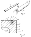
- a refrigeration circuit (not shown in its entirety) comprises a pipe 1 for containing a refrigerant fluid such as isobutane.
- the pipe 1 is arranged to be positioned within the cabinet of a refrigeration appliance or domestic refrigerator 5 (shown only partly) comprising a side 6, an internal compartment 7 and a top 8.
- the outer walls 9 and inner walls 10 of the refrigerator define a usual interspace containing a usual thermoinsulating element 11, generally foamed polyurethane.
- the pipe 1 is positioned within this latter.
- said pipe ( Figures 1 and 2) is at least partly covered with an isolation element 13 comprising a body 17 of substantially cylindrical shape (generally of circular cross-section in the example), slotted longitudinally at 14 and provided with an internal cavity 15 able to contain the pipe 1.
- the body 17 is of open-cell structure and is arranged to enclose the pipe 1 advantageously such that the slot 14 faces an outer wall 9 of the cabinet 3.
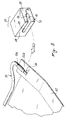
- Figures 3 and 4 show a modification of the invention.
- the element 13 is associated with a circuit region 20 between a refrigerant fluid pipe 21 and a plate evaporator 22.
- the connection between these parts is formed in the usual manner, for example by welding.
- the element 13 comprises a body 17 of polyhedral shape provided with apertures 25 and 26 opening into its two adjacent sides 28 and 29. These apertures enable those portions 21A and 22A of the pipe 21 and plate 22 in proximity to the region 20 to be inserted into the inner cavity 15 of the body 17, which cavity is shaped in such a manner as to receive said portions.
- the body 17 of the element 13 shown in Figures 1 to 4 has an open-cell structure and is formed for example of polyurethane. It can be flexible or rigid and can be formed by reacting isocyanates and/or polyesters or polyesters with added foaming agents and/or catalysts of known type.
- the constituent material of the body 17 can either be a virgin material or can originate from recycling or from salvage and re-working of pieces already formed and used (such as the thermoinsulating material present in scrap refrigerators).
- the body 17 can also be formed independently of the refrigerator by moulding, continuous casting and/or rolling.
- the body obtained in this manner is finished to the required dimensions and fitted to the refrigeration circuit before the final completion of the refrigerator, ie before introducing the thermoinsulating material into the cabinet 3.
- thermoinsulating material is fed into the cabinet 3 substantially simultaneously with the feed into said cabinet of the material which is to form the open-cell structure of the body 17 of each element 13.
- This second method of forming each element 13 positioned within the cabinet 3 obviously results in the creation of bodies 17 for said elements which are not perfectly geometrical.
- An alternative to this latter method for forming each element 13 is to form apertures within the outer walls 9 of the cabinet 3 in positions corresponding with those regions of the refrigeration circuit to be "covered” with the elements 13, then inject the element 11 into the cabinet, and then subsequently inject into this latter through the apertures in the walls 9 the material which is to form the elements 13.
- each element 13 becomes associated with a corresponding part of the refrigeration circuit (whether this be a circuit region between different parts or an actual part of the circuit, such as a pipe, an evaporator part, etc.) in such a manner as to lie against the outer walls 9 of the refrigerator cabinet 3.
- the gas passes into the open-cell structure of the element 13 adjacent to the cracked circuit region (the gas leaking through the microfracture or microfractures) instead of penetrating into the refrigerator thermoinsulating element 11, which is of higher density than said element 13.
- said element directs the leaking gas (arrows K in Figure 4) towards the adjacent wall 9, from which it can escape to the environment external to the refrigerator.
- This improbable but not impossible gas leakage could possibly also cause cracking 50 of the walls 9, as shown in Figure 4.
- the invention therefore enables a refrigeration circuit to safely use a refrigerant gas which could be potentially dangerous in case of leakage from the circuit, this being achieved by the presence at various parts of the circuit (and in particular at circuit regions where percentage-wise the probability of leakage is greater) of elements 13 shaped and formed in such a manner as to direct this gas towards the outside of the refrigerator in which said circuit is located. This prevents any gas accumulation within the refrigerator, a situation which could lead to obvious problems.
Landscapes
- Engineering & Computer Science (AREA)
- Chemical & Material Sciences (AREA)
- Combustion & Propulsion (AREA)
- Physics & Mathematics (AREA)
- Mechanical Engineering (AREA)
- Thermal Sciences (AREA)
- General Engineering & Computer Science (AREA)
- Refrigerator Housings (AREA)
- Connection Of Batteries Or Terminals (AREA)
Claims (9)
- Kühlgerät (5), wie ein Haushaltskühlschrank, ein Gefrierschrank oder dergleichen, mit Außenwänden (9) und Innenwänden (10), die einen ein Wärmeisolierungselement (11) enthaltenden Zwischenraum bilden, ferner mit einem Isolierungselement (13) für ein Teil des Kühlkreises, wobei das Teil eine Kühlkreiskomponente, beispielsweise eine Rohrleitung (1), ein Verdampfer (22) oder dergleichen, oder ein Kühlkreisbereich (20) zwischen zwei Kühlkreiskomponenten (21, 22) ist und wobei das Isolierungselement (13) einen Körper (17) aufweist, der mit einem Sitz (15) für das genannte Kühlkreisteil versehen ist,
dadurch gekennzeichnet, daß das Isolierungselement (13) eine Struktur von geringerer Dichte als die des Wärmeisolierungselements (11) des Kühlgeräts aufweist, daß der Kühlkreis mindestens teilweise im Wärmeisolierungselement (11) eingebettet ist und daß das Isolierungselement (13) an den Außenwänden (9) des Kühlgeräts anliegt. - Kühlgerät nach Anspruch 1,
dadurch gekennzeichnet, daß der Körper (17) des Isolierungselements (13) eine Offenzellstruktur hat. - Kühlgerät nach Anspruch 1,
dadurch gekennzeichnet, daß das Isolierungselement (13) aus elastischem oder festem Polyurethan besteht. - Kühlgerät nach Anspruch 3,
dadurch gekennzeichnet, daß der Polyurethan-Körper (17) Isocyanate und/oder Polyester mit zugesetzten Ausschäumungsmitteln aufweist. - Kühlgerät nach Anspruch 1,
dadurch gekennzeichnet, daß der Körper (17) aus Material besteht, das aus wiederverwertetem Material stammt: - Kühlgerät nach Anspruch 1,
dadurch gekennzeichnet, daß das Isolierungselement (13) gespritzt ist. - Kühlgerät nach Anspruch 1,
dadurch gekennzeichnet, daß das Isolierungselement (13) durch Rollen geformt ist. - Kühlgerät nach Anspruch 1,
dadurch gekennzeichnet, daß das Isolierungselement (13) durch unmittelbares Spritzen in das Kühlgerät (5) gebildet ist. - Kühlgerät nach Anspruch 8,
dadurch gekennzeichnet, daß die Einspritzung gleichzeitig mit der Einspritzung des Wärmeisolierungsmaterials (11) in das Kühlgerät (5) erfolgt.
Priority Applications (3)
| Application Number | Priority Date | Filing Date | Title |
|---|---|---|---|
| DE1994620567 DE69420567T2 (de) | 1994-11-17 | 1994-11-17 | Kühlgerät mit einem Isolierelement, insbesondere für Anschlussbereiche von Teilen eines Kältekreislaufes |
| ES94118083T ES2136692T3 (es) | 1994-11-17 | 1994-11-17 | Aparato de refrigeracion con elemento aislante, en particular para las regiones de conexion entre piezas de un circuito de refrigeracion. |
| EP19940118083 EP0713066B1 (de) | 1994-11-17 | 1994-11-17 | Kühlgerät mit einem Isolierelement, insbesondere für Anschlussbereiche von Teilen eines Kältekreislaufes |
Applications Claiming Priority (1)
| Application Number | Priority Date | Filing Date | Title |
|---|---|---|---|
| EP19940118083 EP0713066B1 (de) | 1994-11-17 | 1994-11-17 | Kühlgerät mit einem Isolierelement, insbesondere für Anschlussbereiche von Teilen eines Kältekreislaufes |
Publications (2)
| Publication Number | Publication Date |
|---|---|
| EP0713066A1 EP0713066A1 (de) | 1996-05-22 |
| EP0713066B1 true EP0713066B1 (de) | 1999-09-08 |
Family
ID=8216464
Family Applications (1)
| Application Number | Title | Priority Date | Filing Date |
|---|---|---|---|
| EP19940118083 Expired - Lifetime EP0713066B1 (de) | 1994-11-17 | 1994-11-17 | Kühlgerät mit einem Isolierelement, insbesondere für Anschlussbereiche von Teilen eines Kältekreislaufes |
Country Status (3)
| Country | Link |
|---|---|
| EP (1) | EP0713066B1 (de) |
| DE (1) | DE69420567T2 (de) |
| ES (1) | ES2136692T3 (de) |
Families Citing this family (2)
| Publication number | Priority date | Publication date | Assignee | Title |
|---|---|---|---|---|
| DE20319183U1 (de) * | 2003-12-10 | 2005-05-04 | Liebherr-Hausgeräte Ochsenhausen GmbH | Kühl- und/oder Gefriergerät |
| DE102008027587A1 (de) * | 2008-05-08 | 2009-11-12 | Liebherr-Hausgeräte Ochsenhausen GmbH | Kühl- und/oder Gefriergerät sowie Verfahren für ein Kühl- und/oder Gefriergerät |
Family Cites Families (3)
| Publication number | Priority date | Publication date | Assignee | Title |
|---|---|---|---|---|
| US1829748A (en) * | 1926-11-30 | 1931-11-03 | Frigidaire Corp | Refrigerating apparatus |
| DE1451113A1 (de) * | 1964-07-10 | 1968-12-05 | Siemens Elektrogeraete Gmbh | Schaumstoffwand,die mit einer Vertiefung zum Einsetzen von Konstruktionsteilen versehen ist |
| DE7239902U (de) * | 1972-10-31 | 1973-07-05 | Bosch R Gmbh | Kuehlmoebel insbesondere kuehlschrank oder dergleichen |
-
1994
- 1994-11-17 EP EP19940118083 patent/EP0713066B1/de not_active Expired - Lifetime
- 1994-11-17 DE DE1994620567 patent/DE69420567T2/de not_active Expired - Lifetime
- 1994-11-17 ES ES94118083T patent/ES2136692T3/es not_active Expired - Lifetime
Also Published As
| Publication number | Publication date |
|---|---|
| DE69420567D1 (de) | 1999-10-14 |
| DE69420567T2 (de) | 2000-05-04 |
| EP0713066A1 (de) | 1996-05-22 |
| ES2136692T3 (es) | 1999-12-01 |
Similar Documents
| Publication | Publication Date | Title |
|---|---|---|
| CA2275104C (en) | Integrated vacuum panel insulation for thermal cabinet structures | |
| US8197019B2 (en) | Refrigerator body and method of manufacturing the same | |
| US6336693B2 (en) | Full vacuum heat insulation box body and method for producing and disassembling the same | |
| KR19990063600A (ko) | 보강단열패널 | |
| EP0713066B1 (de) | Kühlgerät mit einem Isolierelement, insbesondere für Anschlussbereiche von Teilen eines Kältekreislaufes | |
| US3674359A (en) | Refrigerator cabinet with removable partition | |
| US5560695A (en) | Venting device | |
| CN111189277A (zh) | 冰箱 | |
| JP2002318057A (ja) | 冷蔵庫 | |
| US3370739A (en) | Refrigerating apparatus | |
| ITMI940608U1 (it) | Elemento di isolamento in particolare delle zone di giunzione di parti di un circuito refrigerante | |
| GB2171189A (en) | Storage cabinets and their manufacture | |
| JPH0796528A (ja) | 断熱箱体の製造方法 | |
| KR0111188Y1 (ko) | 전기 냉장고 | |
| KR0133703Y1 (ko) | 직냉식 냉장고 | |
| JP2002156178A (ja) | 冷蔵庫の製造方法 | |
| KR930022032A (ko) | 냉장고 | |
| JPS6310354B2 (de) | ||
| JP2570841Y2 (ja) | 冷蔵庫 | |
| KR19980040252U (ko) | 냉장고의 단열재공기 배출장치 | |
| KR20040095549A (ko) | 냉장고의 도어구조 | |
| JPH06129760A (ja) | 冷蔵庫の断熱箱体 | |
| JPH109758A (ja) | 冷蔵庫 | |
| KR100199974B1 (ko) | 냉장고용 도어 | |
| CA1151480A (en) | Water heater construction and fabrication method therefore |
Legal Events
| Date | Code | Title | Description |
|---|---|---|---|
| PUAI | Public reference made under article 153(3) epc to a published international application that has entered the european phase |
Free format text: ORIGINAL CODE: 0009012 |
|
| AK | Designated contracting states |
Kind code of ref document: A1 Designated state(s): DE ES FR GB |
|
| 17P | Request for examination filed |
Effective date: 19961108 |
|
| 17Q | First examination report despatched |
Effective date: 19971218 |
|
| GRAG | Despatch of communication of intention to grant |
Free format text: ORIGINAL CODE: EPIDOS AGRA |
|
| GRAG | Despatch of communication of intention to grant |
Free format text: ORIGINAL CODE: EPIDOS AGRA |
|
| GRAH | Despatch of communication of intention to grant a patent |
Free format text: ORIGINAL CODE: EPIDOS IGRA |
|
| GRAH | Despatch of communication of intention to grant a patent |
Free format text: ORIGINAL CODE: EPIDOS IGRA |
|
| GRAA | (expected) grant |
Free format text: ORIGINAL CODE: 0009210 |
|
| AK | Designated contracting states |
Kind code of ref document: B1 Designated state(s): DE ES FR GB |
|
| RIN1 | Information on inventor provided before grant (corrected) |
Inventor name: GASPERINI, SERGIO, WHIRLPOOL EUROPE S.R.L. Inventor name: BIANCHI, MARIO, WHIRLPOOL EUROPE S.R.L. Inventor name: GRILLO, FRANCO, WHIRLPOOL EUROPE S.R.L. |
|
| REF | Corresponds to: |
Ref document number: 69420567 Country of ref document: DE Date of ref document: 19991014 |
|
| REG | Reference to a national code |
Ref country code: ES Ref legal event code: FG2A Ref document number: 2136692 Country of ref document: ES Kind code of ref document: T3 |
|
| ET | Fr: translation filed | ||
| PLBE | No opposition filed within time limit |
Free format text: ORIGINAL CODE: 0009261 |
|
| STAA | Information on the status of an ep patent application or granted ep patent |
Free format text: STATUS: NO OPPOSITION FILED WITHIN TIME LIMIT |
|
| 26N | No opposition filed | ||
| REG | Reference to a national code |
Ref country code: GB Ref legal event code: IF02 |
|
| PGFP | Annual fee paid to national office [announced via postgrant information from national office to epo] |
Ref country code: FR Payment date: 20131108 Year of fee payment: 20 Ref country code: DE Payment date: 20131113 Year of fee payment: 20 Ref country code: GB Payment date: 20131113 Year of fee payment: 20 |
|
| PGFP | Annual fee paid to national office [announced via postgrant information from national office to epo] |
Ref country code: ES Payment date: 20131011 Year of fee payment: 20 |
|
| REG | Reference to a national code |
Ref country code: DE Ref legal event code: R071 Ref document number: 69420567 Country of ref document: DE |
|
| REG | Reference to a national code |
Ref country code: GB Ref legal event code: PE20 Expiry date: 20141116 |
|
| PG25 | Lapsed in a contracting state [announced via postgrant information from national office to epo] |
Ref country code: GB Free format text: LAPSE BECAUSE OF EXPIRATION OF PROTECTION Effective date: 20141116 |
|
| REG | Reference to a national code |
Ref country code: ES Ref legal event code: FD2A Effective date: 20150826 |
|
| PG25 | Lapsed in a contracting state [announced via postgrant information from national office to epo] |
Ref country code: ES Free format text: LAPSE BECAUSE OF EXPIRATION OF PROTECTION Effective date: 20141118 |