EP0712345B1 - Tete de soudage au laser et son procede de fonctionnement - Google Patents
Tete de soudage au laser et son procede de fonctionnement Download PDFInfo
- Publication number
- EP0712345B1 EP0712345B1 EP94926132A EP94926132A EP0712345B1 EP 0712345 B1 EP0712345 B1 EP 0712345B1 EP 94926132 A EP94926132 A EP 94926132A EP 94926132 A EP94926132 A EP 94926132A EP 0712345 B1 EP0712345 B1 EP 0712345B1
- Authority
- EP
- European Patent Office
- Prior art keywords
- welding head
- laser welding
- flow
- head according
- flow channel
- Prior art date
- Legal status (The legal status is an assumption and is not a legal conclusion. Google has not performed a legal analysis and makes no representation as to the accuracy of the status listed.)
- Expired - Lifetime
Links
Images

Classifications
-
- B—PERFORMING OPERATIONS; TRANSPORTING
- B23—MACHINE TOOLS; METAL-WORKING NOT OTHERWISE PROVIDED FOR
- B23K—SOLDERING OR UNSOLDERING; WELDING; CLADDING OR PLATING BY SOLDERING OR WELDING; CUTTING BY APPLYING HEAT LOCALLY, e.g. FLAME CUTTING; WORKING BY LASER BEAM
- B23K26/00—Working by laser beam, e.g. welding, cutting or boring
- B23K26/14—Working by laser beam, e.g. welding, cutting or boring using a fluid stream, e.g. a jet of gas, in conjunction with the laser beam; Nozzles therefor
- B23K26/1462—Nozzles; Features related to nozzles
- B23K26/1464—Supply to, or discharge from, nozzles of media, e.g. gas, powder, wire
- B23K26/1476—Features inside the nozzle for feeding the fluid stream through the nozzle
-
- B—PERFORMING OPERATIONS; TRANSPORTING
- B23—MACHINE TOOLS; METAL-WORKING NOT OTHERWISE PROVIDED FOR
- B23K—SOLDERING OR UNSOLDERING; WELDING; CLADDING OR PLATING BY SOLDERING OR WELDING; CUTTING BY APPLYING HEAT LOCALLY, e.g. FLAME CUTTING; WORKING BY LASER BEAM
- B23K26/00—Working by laser beam, e.g. welding, cutting or boring
- B23K26/14—Working by laser beam, e.g. welding, cutting or boring using a fluid stream, e.g. a jet of gas, in conjunction with the laser beam; Nozzles therefor
- B23K26/142—Working by laser beam, e.g. welding, cutting or boring using a fluid stream, e.g. a jet of gas, in conjunction with the laser beam; Nozzles therefor for the removal of by-products
-
- B—PERFORMING OPERATIONS; TRANSPORTING
- B23—MACHINE TOOLS; METAL-WORKING NOT OTHERWISE PROVIDED FOR
- B23K—SOLDERING OR UNSOLDERING; WELDING; CLADDING OR PLATING BY SOLDERING OR WELDING; CUTTING BY APPLYING HEAT LOCALLY, e.g. FLAME CUTTING; WORKING BY LASER BEAM
- B23K26/00—Working by laser beam, e.g. welding, cutting or boring
- B23K26/14—Working by laser beam, e.g. welding, cutting or boring using a fluid stream, e.g. a jet of gas, in conjunction with the laser beam; Nozzles therefor
- B23K26/1435—Working by laser beam, e.g. welding, cutting or boring using a fluid stream, e.g. a jet of gas, in conjunction with the laser beam; Nozzles therefor involving specially adapted flow control means
- B23K26/1437—Working by laser beam, e.g. welding, cutting or boring using a fluid stream, e.g. a jet of gas, in conjunction with the laser beam; Nozzles therefor involving specially adapted flow control means for flow rate control
Definitions
- the invention relates to a laser welding head, as is known for example from US-A-5,148,446.
- the invention also relates to a method for operating a laser welding head.
- a laser welding head is known from US Pat. No. 5,148,446, in which a laminar gas flow is generated transversely to the propagation device of the laser beam in order to prevent welding spatter from being deposited on the focusing optics.
- the gas flows relatively slowly and with a high flow cross-section across the laser beam.
- German patent application 35 13 501 discloses a laser welding head which contains a nozzle for generating a transverse gas flow between an optical system for focusing the laser beam and the beam focus. This gas flow serves to deflect particles moving out of the welding melt in the direction of the focusing optics. Opposite the nozzle is the receiving opening of a gas discharge line, which receives the gas flow in its entire cross-sectional extent, including its turbulence area.
- an injector jacket surrounding the nozzle is additionally provided in the known laser welding head, by means of which an laminar-flowing flow jacket surrounding the fast gas flow is generated.
- This protective jacket also reduces turbulence in the welding area, which leads to a fault and Breakthrough of a protective gas atmosphere to be maintained in the welding area.
- the invention is based on the object of specifying a laser welding head which, in a compact design, enables reliable protection of the optical components located in the beam path of the laser beam.
- a method for operating the laser welding head is to be specified.
- a laser welding head comprises a housing in which there is an outlet opening for a focused laser beam and an inside the housing, arranged above the outlet opening Section of a flow channel for a laminar gas flow are located.
- the invention is based on the knowledge that a safe deflection and entrainment of the weld spatter is not guaranteed in a turbulent gas flow even when there is a high gas velocity. This is due to the fact that the turbulence within the gas flow also accelerates some of the weld spatter, which emerge from the melt at a speed of approximately 10 m / s in galvanized steels and have a diameter of approximately 1 mm, against the direction of propagation of the laser beam can be. It has been found that a much more effective deflection of the welding particles can be generated by a laminar gas flow.
- the drag coefficient C D depends on whether the flow is turbulent or laminar. It has been shown that this entrainment coefficient C D is higher for a laminar disturbance than for a turbulent flow.
- means for laminarizing the flow in particular a baffle plate, are arranged in a section of the flow channel lying in front of the outlet opening.
- the flow channel preferably has means for generating a negative pressure in the region of the outlet opening. This creates a slight gas flow from the weld metal to the outlet opening.
- An adjustable step-shaped cross-sectional widening in particular in the form of a sleeve inserted into the outlet opening, is preferably provided.
- the laser welding head contains a protective chamber in which the laser beam spreads before reaching the flow channel, as well as means for generating an overpressure in this protective chamber. It is preferably done in that the protective chamber is connected to the high pressure side of the flow channel in terms of flow technology. This creates an additional light flow directed away from the optical components in the direction of the outlet opening.
- the pressure and flow conditions in the flow channel are selected such that a laminar flow with a flow speed of at least 100 m / s, in particular almost 300 m / s, is present in the region of the outlet opening.
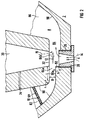
- a laser welding head contains a housing 2 with an outlet opening 4 for a focused laser beam 6.
- the housing 2 is arranged on a flange 22. which receives a protective window 24 for protecting a focusing optics (not shown in the figure) arranged behind the laser welding head.
- the outlet opening 4 is formed by an exchangeable sleeve 28 inserted into an opening 26 of the housing 2.
- a U-shaped flow channel 8 for a gas stream 12 flowing laminarly at least in the area of the outlet opening 4. Air or nitrogen, for example, is suitable as the gas.
- the flow channel 8 comprises several sections arranged one behind the other, each of which has different functions.
- An acceleration chamber 82 is formed by the left leg of the U-shaped flow channel 8 and is connected to a flexible gas line, for example a flexible gas line, which is not shown in the figure and which is led from the outside to the laser welding head.
- the acceleration chamber 82 causes the gas flowing into it to be deflected by approximately 90 ° and causes an acceleration of the gas flow due to the nozzle-shaped narrowing of its cross section.
- the acceleration chamber 82 is followed by a transverse channel 84 oriented transversely to the direction of propagation of the focused laser beam 6.
- This transverse channel 84 is open to the outlet opening 4 and is provided opposite this outlet opening 4 with a further lateral opening 32 through which the focused laser beam 6 enters the transverse channel 84, so that the gas stream 12 flowing therein and the focused laser beam 6 intersect .
- the opening 32 leads into a truncated cone-shaped protective chamber 30, in which the focused laser beam 6 spreads between the transverse channel 84 and the protective window 24.
- the frustoconical protective chamber 30 is provided with a bore 34, with which a connection is made to the acceleration chamber 82, in which a higher pressure prevails than in the area of the opening 32 of the protective chamber 30.
- the transverse channel 84 opens into an expansion chamber 86 which again deflects the gas flow by approximately 90 °, from which the flowing gas leaves the housing 2 through a lateral exhaust opening 87.
- the upper and lower wall surfaces 88 of the flow channel 8 are flat and border on side walls 90 which are curved in sections and extend perpendicularly thereto.
- the flow cross section is reduced by a factor of 4 to 8 in order to enable the gas speed to be increased to approximately 300 m / s or approximately 90% of the speed of sound.
- a baffle plate 10 for forming the gas flow 12 is inserted, the thickness of which is, for example, 2 mm and which has a multiplicity of openings 101 with a diameter of approximately 1 mm.
- the storage plate has a square surface with an edge length of 11 mm and contains 150 bores 101 with a diameter of approximately 0.6 mm.
- the laser welding head preferably also contains additional devices with which a protective gas atmosphere is generated and maintained in the area of the welding point.
- a plurality of small discharge openings 40 are arranged in a ring around the outlet opening 4, through which protective gas emerges from channels running within the housing 2 and not shown in the figure, essentially parallel to the laser beam and surrounds it concentrically.
- a coherent annular outflow opening can also be provided.
- FIG. 2 it can be seen that in a first section 84a of the transverse channel 84 directly adjoining the acceleration chamber 82, a Formation of the gas stream 12 takes place.
- this first section 84a is provided with flat side walls 90a and has a length L which is at least approximately two to three times its width B. In the exemplary embodiment, the length L is approximately 9 mm and the width is approximately 2 mm.
- This first section 84a is followed by a second section 84b, the cross section of which in the form of a step 92 is widened compared to the cross section of the first section 84a.
- This stage 92 is fixed by a sleeve 28 inserted into an opening 26 of the housing 2, for example screwed in, and causes an ejector effect which leads to the fact that an external suction flow 14 results from the outside of the housing 2 towards the flow channel 8, the extent of which the height h of level 92 can be adjusted.
- this height h can be set from 0 to 5 mm.
- the cross section of the exit window 4 for the laser beam is defined by the sleeve 28.
- the inner surface of the sleeve 28 is conically shaped in accordance with the particularly preferred exemplary embodiment of the figure, in order to be able to limit this cross section to the extent necessary for the propagation of the laser beam.
- the gas flow is also deflected in the acceleration chamber 82.
- the radii of curvature r of the side walls 90 must not be too small, since otherwise a conversion into a turbulent flow takes place. It has been shown that with radii of curvature r in the range from 2 to 6 mm a laminarity the gas flow can be maintained even at speeds close to the speed of sound.
Landscapes
- Physics & Mathematics (AREA)
- Optics & Photonics (AREA)
- Engineering & Computer Science (AREA)
- Plasma & Fusion (AREA)
- Mechanical Engineering (AREA)
- Fluid Mechanics (AREA)
- Laser Beam Processing (AREA)
Abstract
Claims (12)
- Tête de soudage au laser comportant un boîtier (2), dans lequel se trouve une ouverture (4) de sortie destinée à un rayon (6) laser focalisé, et comportant une conduite (8) d'écoulement, qui s'étend à l'intérieur du boîtier (2) et qui comporte un tronçon (84), disposé au-dessus de l'ouverture (4) de sortie et destiné à un courant (12) gazeux qui est laminaire dans la zone de l'ouverture (4) de sortie, caractérisée en ce qu'il est prévu un tronçon (82) qui se trouve, dans le sens d'écoulement, en amont de l'ouverture (4) de sortie, dont la section transversale se rétrécit en forme de buse pour augmenter la vitesse des gaz et dans lequel sont disposés des moyens (10) pour rendre laminaire le courant (12) gazeux.
- Tête de soudage au laser suivant la revendication 1, caractérisée en ce qu'il est prévu comme moyen de rendre laminaire le courant une chicane (10) en forme de plaque munie d'ouvertures (101).
- Tête de soudage au laser suivant l'une des revendications précédentes, caractérisée en ce que la conduite (8) d'écoulement comporte des moyens (92) servant à produire une dépression dans la zone de l'ouverture (4) de sortie.
- Tête de soudage au laser suivant la revendication 3, caractérisée en ce qu'il est prévu un élargissement (92) de section transversale réglable en forme de palier.
- Tête de soudage au laser suivant la revendication 4, caractérisée en ce que l'élargissement (92) de section transversale en forme de palier est formé par un manchon (28) introduit dans une ouverture (26) du boîtier (2).
- Tête de soudage au laser suivant la revendication 5, caractérisée en ce que le diamètre intérieur du manchon (28) diminue dans le sens de propagation du rayon (6) laser.
- Tête de soudage au laser suivant l'une des revendications précédentes, caractérisée en ce que, dans la zone de l'ouverture (4) de sortie, la conduite (8) d'écoulement s'étend perpendiculairement à la direction de propagation du rayon (6) laser.
- Tête de soudage au laser suivant l'une des revendications précédentes, caractérisée en ce que la conduite (8) d'écoulement a un tracé en forme de U.
- Tête de soudage au laser suivant l'une des revendications précédentes, caractérisée en ce qu'il est prévu des moyens pour produire une surpression dans une chambre (30) protectrice qui débouche dans la conduite (8) d'écoulement et dans laquelle le rayon (6) laser se propage avant d'avoir atteint la conduite (8) d'écoulement.
- Tête de soudage au laser suivant la revendication 9, caractérisée en ce que la chambre (30) protectrice communique du point de vue de l'écoulement avec le tronçon (82) de la conduite (8) d'écoulement qui se trouve, dans le sens de propagation, en amont de l'ouverture (4) de sortie.
- Procédé pour faire fonctionner une tête de soudage au laser suivant l'une des revendications précédentes, caractérisé en ce que l'on choisit les conditions de pression et d'écoulement dans la conduite (8) d'écoulement de manière à avoir, dans la région de l'ouverture (4) de sortie, un écoulement (12) gazeux s'écoulant de manière laminaire et ayant une vitesse d'écoulement d'au moins 100 m/s.
- Procédé pour faire fonctionner une tête de soudage au laser suivant la revendication 11, caractérisé en ce que la vitesse d'écoulement est proche de 90 % de la vitesse du son.
Applications Claiming Priority (3)
| Application Number | Priority Date | Filing Date | Title |
|---|---|---|---|
| DE4325929 | 1993-08-02 | ||
| DE4325929 | 1993-08-02 | ||
| PCT/EP1994/002525 WO1995003911A1 (fr) | 1993-08-02 | 1994-07-29 | Tete de soudage au laser et son procede de fonctionnement |
Publications (2)
| Publication Number | Publication Date |
|---|---|
| EP0712345A1 EP0712345A1 (fr) | 1996-05-22 |
| EP0712345B1 true EP0712345B1 (fr) | 1997-01-29 |
Family
ID=6494293
Family Applications (1)
| Application Number | Title | Priority Date | Filing Date |
|---|---|---|---|
| EP94926132A Expired - Lifetime EP0712345B1 (fr) | 1993-08-02 | 1994-07-29 | Tete de soudage au laser et son procede de fonctionnement |
Country Status (4)
| Country | Link |
|---|---|
| EP (1) | EP0712345B1 (fr) |
| JP (1) | JP2669152B2 (fr) |
| DE (1) | DE59401732D1 (fr) |
| WO (1) | WO1995003911A1 (fr) |
Cited By (7)
| Publication number | Priority date | Publication date | Assignee | Title |
|---|---|---|---|---|
| DE202005016574U1 (de) * | 2005-10-20 | 2007-02-08 | Kuka Schweissanlagen Gmbh | Blasvorrichtung für ein Laserwerkzeug |
| DE102006052824A1 (de) * | 2006-11-09 | 2008-05-15 | Bayerische Motoren Werke Ag | Verfahren und Vorrichtung beim Laserstrahlschneiden eines metallischen Bauteils |
| DE10226359B4 (de) * | 2002-06-13 | 2010-08-19 | Precitec Kg | Laserbearbeitungskopf zur Bearbeitung, insbesondere zum Schneiden eines Werkstücks mittels Laserstrahl |
| US10562131B2 (en) | 2017-01-19 | 2020-02-18 | Fanuc Corporation | Laser machine |
| US10799982B2 (en) | 2017-01-19 | 2020-10-13 | Fanuc Corporation | Nozzle for laser processing head |
| EP4000791A3 (fr) * | 2020-11-18 | 2022-06-08 | Robert Bosch GmbH | Dispositif et procédé de liaison des composants |
| EP4219060A1 (fr) * | 2021-09-26 | 2023-08-02 | Contemporary Amperex Technology Co., Limited | Buse de cuivre de soudage laser, dispositif auxiliaire de soudage laser et appareil de soudage laser |
Families Citing this family (13)
| Publication number | Priority date | Publication date | Assignee | Title |
|---|---|---|---|---|
| US5814786A (en) * | 1995-11-08 | 1998-09-29 | Littell International, Inc. | System and method for laser butt-welding |
| AT404914B (de) * | 1996-01-25 | 1999-03-25 | Schuoecker Dieter Dr | Vorrichtung zur abtragenden lasermaterialbearbeitung mit schmelzaustrieb durch eine im bearbeitungskopf angebrachte strahlpumpe |
| DE19632625A1 (de) * | 1996-08-13 | 1998-02-19 | Rofin Sinar Laser Gmbh | Verfahren und Vorrichtung zum Schweißverbinden zweier Bauteile |
| JP3056723B1 (ja) | 1999-01-04 | 2000-06-26 | ファナック株式会社 | レ―ザ加工装置 |
| FR2793179A1 (fr) * | 1999-05-06 | 2000-11-10 | Air Liquide | Installation de soudage ou de coupage par faisceau laser avec dispositif de concentration du flux de gaz d'assistance |
| DE29922544U1 (de) * | 1999-12-22 | 2001-05-03 | Kuka Schweissanlagen Gmbh | Blasvorrichtung für eine Lasereinrichtung |
| DE10203452B4 (de) * | 2002-01-30 | 2007-06-28 | Forschungsgesellschaft für Strahlwerkzeuge -FGSW- mbH | Vorrichtung zur Bearbeitung eines Werkstückes mit einem Laserstrahl |
| DE102005025119B4 (de) * | 2004-05-27 | 2006-09-28 | Highyag Lasertechnologie Gmbh | Vorrichtung zur Standzeiterhöhung von Laser-Bearbeitungsoptiken |
| EP1658921B1 (fr) | 2004-11-17 | 2017-01-18 | TRUMPF Laser GmbH | Appareil de soudage laser pour un laser à haute puissance avec faisceau de haute qualité et optique focale de longue distance focale |
| DE102005043596B4 (de) * | 2005-09-12 | 2009-08-27 | 3D-Micromac Ag | Lasermikrobearbeitungsstation, Strahltransformationseinrichtung und Homogenisierer für eine Lasermikrobearbeitungsstation |
| JP2015009270A (ja) * | 2013-07-02 | 2015-01-19 | 日立建機株式会社 | レーザー加工ヘッド |
| DE102017220162A1 (de) * | 2017-11-13 | 2019-05-16 | Fraunhofer-Gesellschaft zur Förderung der angewandten Forschung e.V. | Bearbeitungskopf |
| LU100538B1 (de) | 2017-12-11 | 2019-06-12 | Highyag Lasertechnologie Gmbh | Vorrichtung zum Schutz von Laseroptiken |
Family Cites Families (4)
| Publication number | Priority date | Publication date | Assignee | Title |
|---|---|---|---|---|
| DE3513501A1 (de) * | 1985-04-16 | 1986-10-16 | Rofin-Sinar Laser GmbH, 2000 Hamburg | Laserschweissgeraet |
| US4992643A (en) * | 1989-08-25 | 1991-02-12 | United States Department Of Energy | Method and device for controlling plume during laser welding |
| US5148446A (en) * | 1991-06-07 | 1992-09-15 | Tektronix, Inc. | Laser objective lens shield |
| JPH0815967A (ja) * | 1994-06-30 | 1996-01-19 | Ricoh Co Ltd | 現像装置 |
-
1994
- 1994-07-29 JP JP7505574A patent/JP2669152B2/ja not_active Expired - Fee Related
- 1994-07-29 DE DE59401732T patent/DE59401732D1/de not_active Expired - Fee Related
- 1994-07-29 EP EP94926132A patent/EP0712345B1/fr not_active Expired - Lifetime
- 1994-07-29 WO PCT/EP1994/002525 patent/WO1995003911A1/fr active IP Right Grant
Cited By (10)
| Publication number | Priority date | Publication date | Assignee | Title |
|---|---|---|---|---|
| DE10226359B4 (de) * | 2002-06-13 | 2010-08-19 | Precitec Kg | Laserbearbeitungskopf zur Bearbeitung, insbesondere zum Schneiden eines Werkstücks mittels Laserstrahl |
| DE202005016574U1 (de) * | 2005-10-20 | 2007-02-08 | Kuka Schweissanlagen Gmbh | Blasvorrichtung für ein Laserwerkzeug |
| DE102006052824A1 (de) * | 2006-11-09 | 2008-05-15 | Bayerische Motoren Werke Ag | Verfahren und Vorrichtung beim Laserstrahlschneiden eines metallischen Bauteils |
| DE102006052824B4 (de) * | 2006-11-09 | 2009-05-07 | Bayerische Motoren Werke Aktiengesellschaft | Verfahren und Vorrichtung beim Laserstrahlschneiden eines metallischen Bauteils |
| US10562131B2 (en) | 2017-01-19 | 2020-02-18 | Fanuc Corporation | Laser machine |
| US10799982B2 (en) | 2017-01-19 | 2020-10-13 | Fanuc Corporation | Nozzle for laser processing head |
| DE102018000442B4 (de) | 2017-01-19 | 2021-10-07 | Fanuc Corporation | Lasermaschine |
| EP4000791A3 (fr) * | 2020-11-18 | 2022-06-08 | Robert Bosch GmbH | Dispositif et procédé de liaison des composants |
| EP4219060A1 (fr) * | 2021-09-26 | 2023-08-02 | Contemporary Amperex Technology Co., Limited | Buse de cuivre de soudage laser, dispositif auxiliaire de soudage laser et appareil de soudage laser |
| EP4219060A4 (fr) * | 2021-09-26 | 2024-05-15 | Contemporary Amperex Technology Co Ltd | Buse de cuivre de soudage laser, dispositif auxiliaire de soudage laser et appareil de soudage laser |
Also Published As
| Publication number | Publication date |
|---|---|
| DE59401732D1 (de) | 1997-03-13 |
| WO1995003911A1 (fr) | 1995-02-09 |
| JPH08510691A (ja) | 1996-11-12 |
| EP0712345A1 (fr) | 1996-05-22 |
| JP2669152B2 (ja) | 1997-10-27 |
Similar Documents
| Publication | Publication Date | Title |
|---|---|---|
| EP0712345B1 (fr) | Tete de soudage au laser et son procede de fonctionnement | |
| DE69726316T2 (de) | Verfahren und vorrichtung zum formen von düsen | |
| EP0741627B1 (fr) | Ensemble buse pour le decoupage au laser | |
| DE4226461C2 (de) | Zahnärztliches Instrument zur Behandlung von Zähnen mittels Laserstrahlen | |
| DE60220343T2 (de) | Schweissvorrichtung mit einem miniaturisierten Laserstrahl | |
| EP2349636B1 (fr) | Buse d'usinage laser pour usiner des tôles ; machine de coupage laser avec une buse correspondante | |
| DE112006001389T5 (de) | Lärmtilger für eine Brennstoffzelle | |
| EP0199095B1 (fr) | Dispositif de soudage par laser | |
| EP0985802A1 (fr) | Orifice pour le refroidissement par pellicule et sa méthode de production | |
| EP3746258B1 (fr) | Dispositif d'alimentation en gaz ainsi que tête d'usinage laser dotée d'un dispositif d'alimentation en gaz | |
| DE102014203576A1 (de) | Laserbearbeitungskopf mit einer werkstücknahen Crossjetdüse | |
| DE102015224115A1 (de) | Laserstrahl-bearbeitungsvorrichtung mit einer einkoppelvorrichtung zum einkoppeln eines fokussierten laserstrahls in einen flüssigkeitsstrahl | |
| DE202016100923U1 (de) | Schweißvorrichtung mit Schutzgasführung | |
| DE102021113430A1 (de) | Verfahren zum Laserstrahltiefschweißen | |
| DE102004034777B4 (de) | Vorrichtung zum Laserschweißen | |
| WO2001018498A1 (fr) | Dispositif pour la mesure d'au moins un parametre d'un milieu en ecoulement dans une conduite | |
| DE102006050059A1 (de) | Düse zur industriellen Bearbeitung | |
| DE4011891C2 (fr) | ||
| EP0780190B1 (fr) | Tête d'usinage au laser et procédé de soudage au laser | |
| EP0119426A1 (fr) | Procédé et dispositif d'étirage à partir d'une filière pour diviser des fusions | |
| DE3931401C2 (de) | Fokussierkopf für Laserschweißanlagen | |
| DE2721197A1 (de) | Vorrichtung zur regelung der dicke einer fluessigen beschichtung eines kontinuierlichen durchlaufenden bandes | |
| DE102019110637A1 (de) | Vorrichtung, System und Verfahren zur Erzeugung eines Gasstroms zum Schutz mindestens eines optischen Elements | |
| DE2747034A1 (de) | Luftduesen-baugruppe fuer vorrichtung zur herstellung von glasfasern | |
| DE8337305U1 (de) | Vorrichtung zum Schneiden von Werkstücken durch einen Laserstrahl |
Legal Events
| Date | Code | Title | Description |
|---|---|---|---|
| PUAI | Public reference made under article 153(3) epc to a published international application that has entered the european phase |
Free format text: ORIGINAL CODE: 0009012 |
|
| 17P | Request for examination filed |
Effective date: 19951205 |
|
| AK | Designated contracting states |
Kind code of ref document: A1 Designated state(s): DE FR GB IT SE |
|
| GRAG | Despatch of communication of intention to grant |
Free format text: ORIGINAL CODE: EPIDOS AGRA |
|
| GRAH | Despatch of communication of intention to grant a patent |
Free format text: ORIGINAL CODE: EPIDOS IGRA |
|
| 17Q | First examination report despatched |
Effective date: 19960624 |
|
| GRAH | Despatch of communication of intention to grant a patent |
Free format text: ORIGINAL CODE: EPIDOS IGRA |
|
| GRAA | (expected) grant |
Free format text: ORIGINAL CODE: 0009210 |
|
| AK | Designated contracting states |
Kind code of ref document: B1 Designated state(s): DE FR GB IT SE |
|
| REF | Corresponds to: |
Ref document number: 59401732 Country of ref document: DE Date of ref document: 19970313 |
|
| ITF | It: translation for a ep patent filed |
Owner name: 0508;07MIFSTUDIO JAUMANN |
|
| ET | Fr: translation filed | ||
| GBT | Gb: translation of ep patent filed (gb section 77(6)(a)/1977) |
Effective date: 19970501 |
|
| PLBE | No opposition filed within time limit |
Free format text: ORIGINAL CODE: 0009261 |
|
| STAA | Information on the status of an ep patent application or granted ep patent |
Free format text: STATUS: NO OPPOSITION FILED WITHIN TIME LIMIT |
|
| 26N | No opposition filed | ||
| REG | Reference to a national code |
Ref country code: GB Ref legal event code: IF02 |
|
| PGFP | Annual fee paid to national office [announced via postgrant information from national office to epo] |
Ref country code: GB Payment date: 20020708 Year of fee payment: 9 |
|
| PGFP | Annual fee paid to national office [announced via postgrant information from national office to epo] |
Ref country code: FR Payment date: 20020717 Year of fee payment: 9 |
|
| PGFP | Annual fee paid to national office [announced via postgrant information from national office to epo] |
Ref country code: SE Payment date: 20020723 Year of fee payment: 9 |
|
| PGFP | Annual fee paid to national office [announced via postgrant information from national office to epo] |
Ref country code: DE Payment date: 20020920 Year of fee payment: 9 |
|
| PG25 | Lapsed in a contracting state [announced via postgrant information from national office to epo] |
Ref country code: GB Free format text: LAPSE BECAUSE OF NON-PAYMENT OF DUE FEES Effective date: 20030729 |
|
| PG25 | Lapsed in a contracting state [announced via postgrant information from national office to epo] |
Ref country code: SE Free format text: LAPSE BECAUSE OF NON-PAYMENT OF DUE FEES Effective date: 20030730 |
|
| PG25 | Lapsed in a contracting state [announced via postgrant information from national office to epo] |
Ref country code: DE Free format text: LAPSE BECAUSE OF NON-PAYMENT OF DUE FEES Effective date: 20040203 |
|
| EUG | Se: european patent has lapsed | ||
| GBPC | Gb: european patent ceased through non-payment of renewal fee |
Effective date: 20030729 |
|
| PG25 | Lapsed in a contracting state [announced via postgrant information from national office to epo] |
Ref country code: FR Free format text: LAPSE BECAUSE OF NON-PAYMENT OF DUE FEES Effective date: 20040331 |
|
| REG | Reference to a national code |
Ref country code: FR Ref legal event code: ST |
|
| PG25 | Lapsed in a contracting state [announced via postgrant information from national office to epo] |
Ref country code: IT Free format text: LAPSE BECAUSE OF NON-PAYMENT OF DUE FEES;WARNING: LAPSES OF ITALIAN PATENTS WITH EFFECTIVE DATE BEFORE 2007 MAY HAVE OCCURRED AT ANY TIME BEFORE 2007. THE CORRECT EFFECTIVE DATE MAY BE DIFFERENT FROM THE ONE RECORDED. Effective date: 20050729 |