EP0712246B1 - Bildverarbeitungsgerät und -editiersystem - Google Patents
Bildverarbeitungsgerät und -editiersystem Download PDFInfo
- Publication number
- EP0712246B1 EP0712246B1 EP95919656A EP95919656A EP0712246B1 EP 0712246 B1 EP0712246 B1 EP 0712246B1 EP 95919656 A EP95919656 A EP 95919656A EP 95919656 A EP95919656 A EP 95919656A EP 0712246 B1 EP0712246 B1 EP 0712246B1
- Authority
- EP
- European Patent Office
- Prior art keywords
- time
- image
- memory
- images
- editing
- Prior art date
- Legal status (The legal status is an assumption and is not a legal conclusion. Google has not performed a legal analysis and makes no representation as to the accuracy of the status listed.)
- Expired - Lifetime
Links
Images


Classifications
-
- G—PHYSICS
- G06—COMPUTING OR CALCULATING; COUNTING
- G06T—IMAGE DATA PROCESSING OR GENERATION, IN GENERAL
- G06T1/00—General purpose image data processing
- G06T1/20—Processor architectures; Processor configuration, e.g. pipelining
-
- G—PHYSICS
- G11—INFORMATION STORAGE
- G11B—INFORMATION STORAGE BASED ON RELATIVE MOVEMENT BETWEEN RECORD CARRIER AND TRANSDUCER
- G11B27/00—Editing; Indexing; Addressing; Timing or synchronising; Monitoring; Measuring tape travel
- G11B27/02—Editing, e.g. varying the order of information signals recorded on, or reproduced from, record carriers
- G11B27/022—Electronic editing of analogue information signals, e.g. audio or video signals
- G11B27/028—Electronic editing of analogue information signals, e.g. audio or video signals with computer assistance
-
- G—PHYSICS
- G11—INFORMATION STORAGE
- G11B—INFORMATION STORAGE BASED ON RELATIVE MOVEMENT BETWEEN RECORD CARRIER AND TRANSDUCER
- G11B27/00—Editing; Indexing; Addressing; Timing or synchronising; Monitoring; Measuring tape travel
- G11B27/02—Editing, e.g. varying the order of information signals recorded on, or reproduced from, record carriers
- G11B27/031—Electronic editing of digitised analogue information signals, e.g. audio or video signals
- G11B27/032—Electronic editing of digitised analogue information signals, e.g. audio or video signals on tapes
-
- G—PHYSICS
- G11—INFORMATION STORAGE
- G11B—INFORMATION STORAGE BASED ON RELATIVE MOVEMENT BETWEEN RECORD CARRIER AND TRANSDUCER
- G11B27/00—Editing; Indexing; Addressing; Timing or synchronising; Monitoring; Measuring tape travel
- G11B27/10—Indexing; Addressing; Timing or synchronising; Measuring tape travel
- G11B27/34—Indicating arrangements
-
- G—PHYSICS
- G11—INFORMATION STORAGE
- G11B—INFORMATION STORAGE BASED ON RELATIVE MOVEMENT BETWEEN RECORD CARRIER AND TRANSDUCER
- G11B2220/00—Record carriers by type
- G11B2220/60—Solid state media
- G11B2220/61—Solid state media wherein solid state memory is used for storing A/V content
-
- G—PHYSICS
- G11—INFORMATION STORAGE
- G11B—INFORMATION STORAGE BASED ON RELATIVE MOVEMENT BETWEEN RECORD CARRIER AND TRANSDUCER
- G11B2220/00—Record carriers by type
- G11B2220/90—Tape-like record carriers
-
- G—PHYSICS
- G11—INFORMATION STORAGE
- G11B—INFORMATION STORAGE BASED ON RELATIVE MOVEMENT BETWEEN RECORD CARRIER AND TRANSDUCER
- G11B27/00—Editing; Indexing; Addressing; Timing or synchronising; Monitoring; Measuring tape travel
- G11B27/02—Editing, e.g. varying the order of information signals recorded on, or reproduced from, record carriers
- G11B27/031—Electronic editing of digitised analogue information signals, e.g. audio or video signals
- G11B27/034—Electronic editing of digitised analogue information signals, e.g. audio or video signals on discs
-
- G—PHYSICS
- G11—INFORMATION STORAGE
- G11B—INFORMATION STORAGE BASED ON RELATIVE MOVEMENT BETWEEN RECORD CARRIER AND TRANSDUCER
- G11B27/00—Editing; Indexing; Addressing; Timing or synchronising; Monitoring; Measuring tape travel
- G11B27/10—Indexing; Addressing; Timing or synchronising; Measuring tape travel
Definitions
- This invention relates to an image processing apparatus and a video editing system. More particularly, this invention relates to an image processing apparatus and a system using that in which an editing point of a real-time reproduced image is set by means of a processing apparatus of time-division task type.
- a time code (“hour, minute, second, and a frame number" or “hour, minute, second, a frame number, and a field number”) is given to respective images which are reproduced by a video tape recorder as time information.
- a video processing apparatus used for video editing captures and stores a video image at the point directed to treat by the user in a memory as an editing point image, and displays the stored editing point image and the corresponding time code as one pair.
- the video processing apparatus usually either displays a pair of editing point image of normal size or plural pairs of editing point images of reduced size.
- the processing time is divided into plural time slices, and the respective task is conducted in each time slice.
- an image processing apparatus comprising:
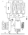
- FIG. 1 shows the general construction of the video editing system according to the embodiment of this invention. The more detailed internal structure of each unit will be described after the following clause again.
- a video editing system 1 shown in FIG. 1 is composed of plural video tape recorders 2 to 4, a video tape recorder controller 5 which controls these recorders, a switcher 6, a workstation 7, and a display device 9.
- the two video tape recorders 2 and 3 are used to reproduce motion picture
- the video tape recorder 4 is used to record motion picture which has been edited based on an editing list (reproducing apparatus information and editing points (a start point, an end point)).
- a video signal and an audio signal reproduced in the video tape recorders 2 and 3 are output as reproduced signals S1 and S2.
- the video tape recorder controller 5 gives control signals S3 to S5 to the video tape recorders 2 to 4 to control their recording/reproducing operation and outputs time information (the Greenwich standard time and a time code) at the time point when the capture instruction of an editing point image is input by a mark key which has been provided on a keyboard 5A, to the workstation 7 as a control command S6.
- time information the Greenwich standard time and a time code
- control command S6 is output to the workstation 7 via a serial transfer interface such as the RS-232C.
- a serial transfer interface such as the RS-232C.
- the video tape recorder controller 5 synchronizes the time of a built-in clock (a clock 5B described later) with the time of a clock built in the workstation 7 (the clock 7B described later) whenever a time synchronizing signal S7 is input via the network 10, so as to prevent the generation of a time lag between two built-in clocks. In this manner, the time of these built-in watches are coincide with each other so that a time lag between the editing point image which has been instructed to be captured to the video tape recorder controller 5 and the editing point image which is captured by the workstation 7 does not occur.
- the switcher 6 effects simple special effects to the reproduced signals S1 and S2 and outputs either signal to the workstation 7 as an editing reproduced signal S8.
- the editing reproduced signal S8 is also output to the display device 9.
- the display device 9 is used to display reproduced motion picture so as to select the editing point image by the user along with the time code added to each picture.
- the work station 7 is a video editing apparatus being a time-division task processing apparatus in which, although a time lag between the time when the capturing of the editing image has been instructed and the time when the command which instructs the capturing of the editing point image is actually processed is generated, the image and the time which correspond to the time point when the capturing is instructed can be captured correctly.
- the work station 7 has a loop buffer memory for always storing plural frame pictures which are past from the newest frame picture. Further, the workstation 7 has a memory for editing point candidate image which stores pictures of plural frames before and after the time point when the capturing of the image was instructed, so that the user can reset it to a more suitable editing point than the editing point which has been instructed roughly by the user.
- the editing point candidate image stored in the memory for editing point candidate image is displayed on the screen of the display device 9 for the user's selection.
- one of the plural editing point candidate images 9A to 9E which are displayed on the screen of the display device 9 can be selected by means of a mouse 7A, and an editing list is made based on the information of the editing point that has been set finally.
- the workstation 7 outputs the editing list as a control data S9 via the network 10 to give it to the video tape recorder controller 5.
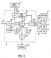
- FIG. 2 shows the circuit structure of the video tape recorder controller 5.
- the video tape recorder controller 5 is composed of a CPU 5C, a sync generator 5D, a ROM 5E, a RAM 5F, and an interface 5G other than the above-mentioned clock 5B.
- the clock 5B gives the Greenwich standard time to the internal circuits, and synchronizing processing is performed periodically so as to match the time with the time of the clock built in the workstation 7.
- the CPU 5C controls the operation of the internal circuits and the operation of the peripheral equipments (the video tape recorders 2 to 4 and the switcher 6) via the interface 5G2.
- the CPU 5C executes various processing in accordance with the processing procedure which has been defined by the software by using the ROM 5E and the RAM 5F.
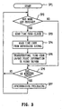
- FIG. 3 shows this processing procedure.
- the CPU 5C starts the processing from step SP1, and at step SP2, it judges whether the mark key which instructs the capture of an editing point image has been pressed or not.
- the CPU 5C judges that the user found an image to use as an editing point (edit start point or edit end point) among the motion pictures displayed on the display device 8, and it proceeds to step SP3 to read-in the current time from the clock 5B.
- the CPU 5C outputs the control signal S10 to the switcher 6 via the interface 5G2 to read-in the value of the time code added to the editing reproduced signal S8 which is to be output now from the switcher 6.
- a time lag of 1 to several clocks is generated between the timing reading in the current time and the timing reading in the time code, however, since the time code is a value having the unit of 1/100 [sec] where as the Greenwich standard time is a value having the unit of 1/1000 [sec], the value read-in at the step SP4 becomes the value of the time point when the mark key was pressed.
- the CPU 5C After the time when the mark key was pressed and the time code are read-in at the steps SP3 and SP4 as the above, at step SP5, the CPU 5C outputs information showing the distinction between an editing start point (IN point) and an editing end point (OUT point) of these time information as a control command S6.
- the control command S6 is transferred to a video driver of the workstation 7 described later.
- step SP6 After finishing the processing of these steps SP3 to SP5, or when a negative result is obtained at the step SP2, the processing of the CPU 5C proceeds to step SF6.
- the CPU 5C judges whether 10 minutes has past from the last synchronizing processing or not. Here, if an affirmative result is obtained, the CPU 5C proceeds to step SP7 to perform the synchronizing processing such that it causes the time of the clock 5B to match with the time of the clock built in the workstation 7. Further, at this time, the CPU 5C causes the built-in watches of the video tape recorders 2 to 4 and the switcher 6 to synchronize with the clock 5B by using the sync generator 5D. Then, after the series of these processing are finished, the CPU 5C returns to the step SP2 to conduct the above-mentioned processing operations repeatedly.
- the CPU 5C returns from the step SP6 to the step SP2 to repeat the series of operations.
- the CPU 5C controls the video tape recorders 2 to 4 based on the contents of this editing list.
- FIG. 4 shows the circuit structure of the workstation 7.
- the workstation 7 is composed of a CPU 7C, an A/D convertor 7D, a driver memory 7E, a loop buffer memory 7F, a memory for editing point candidate image 7G, and an interface 7H in addition to the clock 7B described above.
- the clock 7B gives the Greenwich standard time to the internal circuits and the circumference equipments, and it operates as a basis in this video editing system.
- the CPU 7C is the main circuit of the workstation 7 which executes multi-task by time-division, and controls the capturing of picture data to various memories and the creation of the editing list.
- the CPU 7C stores information showing that this clipped image is the editing start point or the editing end point and its time code in the editing list as a pair.
- the CPU 7C detects that a picture signal for one frame which has been input to the A/D convertor 7D from the switcher 6 was converted into digital data by a flag signal S11 input from the A/D convertor 7D, the CPU 7C starts the video driver 7E1 of the driver memory 7E and sequentially transfers the image which has been converted into digital data to the loop buffer memory 7F as a clipped image.
- FIG. 5 shows the processing procedure by the video driver 7E1.
- the video driver 7E1 starts the processing from step SP11, and at step SP12, it reads-in the time of the clock 7B in order to read-in the time to capture the clipped image.
- the video driver 7E1 After proceeding to the following step SP13, the video driver 7E1 outputs a read-in control signal S12 to the loop buffer memory 7F to instruct the read in of the clipped image, so that the clipped image which has been captured at the oldest time point is updated to the newest clipped image.
- the video driver 7E1 memorizes the clipped image and the Greenwich standard time which is read-in at the step SP12 as a pair, and then terminates the processing.
- the loop buffer memory 7F has a structure in which plural frame memories are connected in series.
- clipped images for 50 to 60 frames can be stored.
- the clipped images for about 2 [sec] are stored in the buffer memory so that a time lag between the time point of capturing the editing image which is given by the control command S6 and the time that the capturing processing is actually executed can be assimilated.
- the memory for editing point candidate image 7G is an image memory which is used to store clipped images necessary for setting the editing point out of the clipped images which has been temporarily stored in the loop buffer memory 7F, in which the clipped images of several tens of frames which precede and follow the clipped image that the user designated as an editing point.
- FIG. 6 shows the processing procedure executed in the transfer task driver 7E2.
- the transfer task driver 7E2 starts the processing from step SP21, and then proceeds to step SP22 to judge whether the control command S6 which instructs the capturing of the editing point image is input or not.
- the transfer task driver 7E2 proceeds to step SP23 to start the operation for searching the clipped image in which A/D conversion has finished at the same time as the time that has been instructed to capture as the editing point (the editing start point or the editing end point), from the loop buffer memory 7F.
- the transfer task driver 7E2 transfer the clipped images for several tens of frames (for example, 15 frames) which precede and follow the clipped image found out, to the memory for editing point candidate image 7G in the processing of step SP24.
- the transfer task driver 7E2 obtains the value of time codes respectively based on the Greenwich time added to each clipped image by calculation and adds it to respective clipped images. At this time, the transfer task driver 7E2 calculates the time code for each clipped image based on the time code sent as the control command S6. This relies upon that the time code not always become continuous values due to the difference in the format of video signals (NTSC/PAL/SECAM/PALM and the like) or existence of dropped frames.
- the transfer task driver 7E2 displays the editing point candidate images 9A to 9E each which is composed of the clipped image converted to a reduced size and the time code, on the screen of the display device 9, and then terminates the series of processing.
- the series of processing in the transfer task driver 7E2 is performed repeatedly every time when the capturing of the editing point image is instructed by the user, and it is memorized to a different area of the memory for editing point candidate image 7G. Then, these editing point candidate images 9A to 9E are displayed on the screen of the display device 9 similar to the editing point candidate images 9A to 9E obtained before then. In this connection, in the case where the all of these plural editing point candidate images cannot be displayed on the screen of the display device 9 at once, it can be displayed by scrolling the screen. The above is the processing operation by the transfer task driver 7E2.
- the user waits for appearance of the image which is suitable to his editing aim while monitoring the motion pictures displayed on the screen of the display device 8 and presses the mark key provided on the keyboard 5A at the scene of the image suitable to his aim.
- the CPU 5C of the video tape recorder controller 5 outputs these time information to the workstation 7 as the control command S6.
- the transfer task driver 7E2 detects a corresponding clipped image based on the Greenwich standard time "1 o'clock 10 minute 10 second 480/1000" which is given by the control command S6 from the loop buffer memory 7F, and transfers clipped images for several tens frames in which the detected one is the center frame, to the memory for editing point candidate image 7G.
- the transfer task driver 7E2 generates a time code to be added to the several tens of frames of clipped images which precede and follow based on the time code given by the control command S6, namely, "21st frame 0 o'clock 40 minute 40 second".
- plural editing point candidate images 9A to 9E in which the clipped image at the time instructed to capture by the user is the center are displayed on the screen of the display device 9.
- the user determines the clipped image of the editing start point by selecting one of the plural editing point candidate images 9A to 9E by means of the mouse 7A or by inputting the time code added to the clipped image to be selected by means of the keyboard or the like.
- the clipped image giving the editing end point can also be set.
- the user can set editing points by this series of tasks.
- the time of the clock 5B which has been built in the video tape recorder controller 5 is matched with the time of the clock 7B which has been built in the workstation 7 previously, and when the capturing of the editing point image is instructed by the user, the time at the instant when the capturing was instructed from the video tape recorder controller 5 and the time code are given to the workstation 7, so that it is possible that the image which is found out by the workstation 7 based on the time of the clock 7B always matches with the image which is aimed by the user.
- the workstation 7 stores the clipped image which is sequentially captured adding the time, and keeps them for a predetermined time.
- a clipped image which has the same time is searched from the loop buffer memory 7F based on the time information given as the control command S6, and several tens of frames preceding and following this clipped image are displayed on the screen added the time code.
- the clipped image aimed by the user can be always extracted and displayed not depending on a time lag between the processing time in the workstation 7 and the time when capturing is instructed by the user.
- the several tens of frames of clipped images preceding and following and including the center frame are displayed on the same screen as the editing point candidate images, so that the final editing start point and a final editing end point can be set while comparing those.
- the visibility improves comparing with the case where the editing work is proceeded depending only on characters of the time code, and the editing work can be conducted more efficiently.
- the video tape recorders 2 to 4 are utilized as reproducing apparatuses for real-time-processing a video signal.
- this invention is not limited to this but may be applied to a magnetic reproducing apparatus such as a magnetic disc apparatus, an optical disc apparatus such as a magneto-optical disc apparatus, or a reproducing apparatus using a semiconductor memory.
- control command S6 is transferred via a serial transfer interface.
- this invention is not limited to this but may be applied to the case of transferring via a network.
- this invention is utilized in an editing apparatus of motion pictures.
- this invention is not limited to this but may be applied to the case where motion pictures between specified time codes are displayed on the screen among picture signals reproduced by one or plural reproducing apparatuses, and the case where the motion picture is displayed on the screen with a projector.
- This invention can be applied to a time-division task processing apparatus which treats real-time pictorial images, for example, an image processing apparatus such as a workstation or a personal computer.
- this invention can also be applied to a video editing system for editing an image by means of these processing apparatuses.
Landscapes
- Engineering & Computer Science (AREA)
- Multimedia (AREA)
- Physics & Mathematics (AREA)
- General Physics & Mathematics (AREA)
- Theoretical Computer Science (AREA)
- General Engineering & Computer Science (AREA)
- Television Signal Processing For Recording (AREA)
- Management Or Editing Of Information On Record Carriers (AREA)
Claims (7)
- Bildverarbeitungsgerät mit:wobei der Kontroller (5) auf einen Eingangsmarkenbefehl anspricht, um der Steuerungseinrichtung (7E) einen Steuerungsbefehl (S6) zuzuführen, der den Wert des ersten Taktsignals zum Zeitpunkt des Markenbefehls und den Wert eines Zeitcode zum Zeitpunkt des Markenbefehls anzeigt, undeiner Bilderzeugungseinrichtung (2, 3) zur Erzeugung einer Folge von Bildern,einem Kontroller (5) für die Bilderzeugungseinrichtung (2, 3), der eine erste Taktgebereinrichtung (5B) zur Erzeugung eines ersten Taktsignals aufweist, undeinem Zeitmultiplex-Multitaskprozessor (7), dereine zweite Taktgebereinrichtung (7B) zur Erzeugung eines zweiten Taktsignals,einen ersten und zweiten Speicher (7F, 7G) undeine Steuerungseinrichtung (7E, 7E1) zum Speichern der Bilder der Folge zusammen mit einem Wert des mit jedem Bild korrespondierenden zweiten Taktsignals im ersten Speicher (7F) aufweist,
wobei die Steuerungseinrichtung (7E/7E2) auf das Befehlssignal (S6) anspricht, um zum zweiten Speicher (7G) mehrere der im ersten Speicher (7F) gespeicherten Bilder zu übertragen, wobei die mehreren Bilder zeitmäßig auf den Wert des ersten Taktsignals zum Zeitpunkt des Markensignals zentriert sind, und um für jedes der mehreren Bilder im zweiten Speicher einen Zeitcodewert zu speichern, der von der Steuerungseinrichtung (7E) aus dem Wert des Zeitcodes zum Zeitpunkt des Markenbefehls berechnet wird. - Bildverarbeitungsgerät nach Anspruch 1, wobei die Folge von Bildern Rahmen eines Realzeit-Videosignals aufweist, wobei der erste Speicher (7F) ein Schleifenpufferspeicher ist, und wobei die Steuerungseinrichtung (7E/7E1) den Inhalt des ersten Speichers aktualisiert, damit er mehrere die neuesten Rahmen in der Folge enthaltende Rahmen aufweist, wobei jeder Rahmen für eine vorbestimmte Zeitperiode im ersten Speicher gespeichert ist.
- Bildverarbeitungsgerät nach Anspruch 2, wobei die Bilderzeugungseinrichtung (2, 3) eine Einrichtung zur Wiedergabe eines gespeicherten Videosignals aufweist.
- Bildverarbeitungsgerät nach Anspruch 1, Anspruch 2 oder Anspruch 3, mit einer seriellen Übertragungsschnittstelle zum Übertragen des Steuerungsbefehls (S6) vom Kontroller (5) zur Steuerungseinrichtung (7E/7E2).
- Bildverarbeitungsgerät nach einem der vorhergehenden Ansprüche, mit einer Anzeigeeinrichtung (9) zum Anzeigen der mehreren zum zweiten Speicher (7G) übertragenen Bilder.
- Bildverarbeitungsgerät nach Anspruch 5, wobei der Zeitmultiplex-Multitaskprozessor (7) auf die Wahl eines angezeigten Bildes anspricht, um die Wahl als Editierdaten (S9) auszugeben.
- Bildverarbeitungsgerät nach einem der vorhergehenden Ansprüche, wobei der Kontroller (5) auf ein Synchronisierungssignal (S7) anspricht, um die erste und zweite Taktgebereinrichtung (5B, 7B) zu synchronisieren.
Applications Claiming Priority (4)
| Application Number | Priority Date | Filing Date | Title |
|---|---|---|---|
| JP139452/94 | 1994-05-30 | ||
| JP13945294 | 1994-05-30 | ||
| JP13945294 | 1994-05-30 | ||
| PCT/JP1995/001027 WO1995033335A1 (en) | 1994-05-30 | 1995-05-29 | Picture processor and picture editing system |
Publications (3)
| Publication Number | Publication Date |
|---|---|
| EP0712246A1 EP0712246A1 (de) | 1996-05-15 |
| EP0712246A4 EP0712246A4 (de) | 1999-06-23 |
| EP0712246B1 true EP0712246B1 (de) | 2002-01-09 |
Family
ID=15245546
Family Applications (1)
| Application Number | Title | Priority Date | Filing Date |
|---|---|---|---|
| EP95919656A Expired - Lifetime EP0712246B1 (de) | 1994-05-30 | 1995-05-29 | Bildverarbeitungsgerät und -editiersystem |
Country Status (5)
| Country | Link |
|---|---|
| US (1) | US6215949B1 (de) |
| EP (1) | EP0712246B1 (de) |
| JP (1) | JP3671420B2 (de) |
| DE (1) | DE69524927D1 (de) |
| WO (1) | WO1995033335A1 (de) |
Families Citing this family (1)
| Publication number | Priority date | Publication date | Assignee | Title |
|---|---|---|---|---|
| JPH10178619A (ja) | 1996-12-19 | 1998-06-30 | Nikon Corp | 画像再生装置および電子カメラ |
Family Cites Families (11)
| Publication number | Priority date | Publication date | Assignee | Title |
|---|---|---|---|---|
| US4100607A (en) * | 1977-02-07 | 1978-07-11 | Convergence Corporation | Computer for video tape editing system |
| JPS59135680A (ja) * | 1983-01-24 | 1984-08-03 | Asaka:Kk | ビデオ編集用ビユワ− |
| DE3577381D1 (de) * | 1984-09-19 | 1990-05-31 | Victor Company Of Japan | Geraet zur synchronisierung verschiedener fernsehsysteme. |
| US4774600A (en) * | 1985-05-06 | 1988-09-27 | Eastman Kodak Company | Video tape editing technique |
| JP2952877B2 (ja) * | 1988-09-30 | 1999-09-27 | ソニー株式会社 | ディスクプレーヤとその再生方法 |
| JPH043384A (ja) * | 1990-04-19 | 1992-01-08 | Matsushita Electric Ind Co Ltd | ビデオテープレコーダの編集コントロール装置 |
| JPH0477188A (ja) * | 1990-07-17 | 1992-03-11 | Matsushita Electric Ind Co Ltd | 磁気記録再生装置 |
| CA2121682A1 (en) * | 1991-10-21 | 1993-04-29 | Ian Craven | On-line video editing system |
| GB2273220B (en) * | 1992-12-07 | 1997-01-08 | Quantel Ltd | A video processing system |
| US5508871A (en) * | 1993-08-30 | 1996-04-16 | Ng; Tat O. | Continuous audio and video tape |
| US5706386A (en) * | 1994-05-24 | 1998-01-06 | Sony Corporation | Image information recording method and apparatus, image information reproducing method and apparatus and editing method and system |
-
1995
- 1995-05-29 US US08/592,380 patent/US6215949B1/en not_active Expired - Fee Related
- 1995-05-29 WO PCT/JP1995/001027 patent/WO1995033335A1/ja not_active Ceased
- 1995-05-29 DE DE69524927T patent/DE69524927D1/de not_active Expired - Lifetime
- 1995-05-29 JP JP52812495A patent/JP3671420B2/ja not_active Expired - Fee Related
- 1995-05-29 EP EP95919656A patent/EP0712246B1/de not_active Expired - Lifetime
Also Published As
| Publication number | Publication date |
|---|---|
| DE69524927D1 (de) | 2002-02-14 |
| JP3671420B2 (ja) | 2005-07-13 |
| US6215949B1 (en) | 2001-04-10 |
| EP0712246A1 (de) | 1996-05-15 |
| EP0712246A4 (de) | 1999-06-23 |
| WO1995033335A1 (en) | 1995-12-07 |
Similar Documents
| Publication | Publication Date | Title |
|---|---|---|
| US6304283B1 (en) | Conference apparatus and method for realistically reproducing image data and shared board data | |
| US5974218A (en) | Method and apparatus for making a digest picture | |
| JP3927608B2 (ja) | 動画像表示装置及び動画像記憶装置 | |
| US5617147A (en) | Transmission system for an aspect-area-ratio position ID signal | |
| JPH06350937A (ja) | 画像合成再生装置 | |
| EP0712246B1 (de) | Bildverarbeitungsgerät und -editiersystem | |
| JP2002199347A (ja) | 画像処理装置、画像処理システム、画像処理方法、及び記憶媒体 | |
| JP2001186471A (ja) | 映像比較装置及び映像比較プログラムを記録した記録媒体 | |
| JP3558813B2 (ja) | 映像監視システム | |
| JPH07162773A (ja) | 画面表示方法 | |
| JPWO1995033335A1 (ja) | 画像処理装置及び画像編集システム | |
| JPH02285867A (ja) | 編集装置 | |
| JPH04192780A (ja) | 監視装置 | |
| US5459618A (en) | Apparatus for producing a video signal representing an animation | |
| JP3085509B2 (ja) | ビデオ一体型テレビにおける文字表示制御方法 | |
| JP2002252830A (ja) | 画像記録装置 | |
| JP2896414B2 (ja) | 表示装置 | |
| CN112423067B (zh) | 视频的播放方法、装置、遥控设备及存储介质 | |
| JP4290238B2 (ja) | 映像合成装置及び方法 | |
| JPH04326261A (ja) | 撮像装置 | |
| JP2854576B2 (ja) | 画像処理装置 | |
| JP3179457B2 (ja) | 画像ファイル装置 | |
| JPH0359696A (ja) | 画像信号の合成装置 | |
| HK40038300A (en) | :video playing method, apparatus, remote control device, and storage medium | |
| HK40038300B (en) | :video playing method, apparatus, remote control device, and storage medium |
Legal Events
| Date | Code | Title | Description |
|---|---|---|---|
| PUAI | Public reference made under article 153(3) epc to a published international application that has entered the european phase |
Free format text: ORIGINAL CODE: 0009012 |
|
| 17P | Request for examination filed |
Effective date: 19960124 |
|
| AK | Designated contracting states |
Kind code of ref document: A1 Designated state(s): DE FR GB |
|
| A4 | Supplementary search report drawn up and despatched |
Effective date: 19990510 |
|
| AK | Designated contracting states |
Kind code of ref document: A4 Designated state(s): DE FR GB |
|
| RIC1 | Information provided on ipc code assigned before grant |
Free format text: 6G 11B 27/032 A, 6G 11B 27/028 B, 6G 11B 27/34 B, 6H 04N 5/782 B, 6H 04N 5/78 B |
|
| 17Q | First examination report despatched |
Effective date: 19991025 |
|
| GRAG | Despatch of communication of intention to grant |
Free format text: ORIGINAL CODE: EPIDOS AGRA |
|
| GRAG | Despatch of communication of intention to grant |
Free format text: ORIGINAL CODE: EPIDOS AGRA |
|
| GRAH | Despatch of communication of intention to grant a patent |
Free format text: ORIGINAL CODE: EPIDOS IGRA |
|
| GRAH | Despatch of communication of intention to grant a patent |
Free format text: ORIGINAL CODE: EPIDOS IGRA |
|
| GRAA | (expected) grant |
Free format text: ORIGINAL CODE: 0009210 |
|
| REG | Reference to a national code |
Ref country code: GB Ref legal event code: IF02 |
|
| AK | Designated contracting states |
Kind code of ref document: B1 Designated state(s): DE FR GB |
|
| REF | Corresponds to: |
Ref document number: 69524927 Country of ref document: DE Date of ref document: 20020214 |
|
| PG25 | Lapsed in a contracting state [announced via postgrant information from national office to epo] |
Ref country code: DE Free format text: LAPSE BECAUSE OF FAILURE TO SUBMIT A TRANSLATION OF THE DESCRIPTION OR TO PAY THE FEE WITHIN THE PRESCRIBED TIME-LIMIT Effective date: 20020410 |
|
| PG25 | Lapsed in a contracting state [announced via postgrant information from national office to epo] |
Ref country code: GB Free format text: LAPSE BECAUSE OF NON-PAYMENT OF DUE FEES Effective date: 20020529 |
|
| ET | Fr: translation filed | ||
| PLBE | No opposition filed within time limit |
Free format text: ORIGINAL CODE: 0009261 |
|
| STAA | Information on the status of an ep patent application or granted ep patent |
Free format text: STATUS: NO OPPOSITION FILED WITHIN TIME LIMIT |
|
| 26N | No opposition filed | ||
| GBPC | Gb: european patent ceased through non-payment of renewal fee |
Effective date: 20020529 |
|
| PG25 | Lapsed in a contracting state [announced via postgrant information from national office to epo] |
Ref country code: FR Free format text: LAPSE BECAUSE OF NON-PAYMENT OF DUE FEES Effective date: 20030131 |
|
| REG | Reference to a national code |
Ref country code: FR Ref legal event code: ST |