EP0711459B1 - Akkumulator mit kunststoffgehäuse - Google Patents
Akkumulator mit kunststoffgehäuse Download PDFInfo
- Publication number
- EP0711459B1 EP0711459B1 EP94921575A EP94921575A EP0711459B1 EP 0711459 B1 EP0711459 B1 EP 0711459B1 EP 94921575 A EP94921575 A EP 94921575A EP 94921575 A EP94921575 A EP 94921575A EP 0711459 B1 EP0711459 B1 EP 0711459B1
- Authority
- EP
- European Patent Office
- Prior art keywords
- casing
- battery according
- plastic
- soft plastic
- housing
- Prior art date
- Legal status (The legal status is an assumption and is not a legal conclusion. Google has not performed a legal analysis and makes no representation as to the accuracy of the status listed.)
- Expired - Lifetime
Links
Images



Classifications
-
- H—ELECTRICITY
- H01—ELECTRIC ELEMENTS
- H01M—PROCESSES OR MEANS, e.g. BATTERIES, FOR THE DIRECT CONVERSION OF CHEMICAL ENERGY INTO ELECTRICAL ENERGY
- H01M50/00—Constructional details or processes of manufacture of the non-active parts of electrochemical cells other than fuel cells, e.g. hybrid cells
- H01M50/30—Arrangements for facilitating escape of gases
- H01M50/317—Re-sealable arrangements
- H01M50/325—Re-sealable arrangements comprising deformable valve members, e.g. elastic or flexible valve members
-
- H—ELECTRICITY
- H01—ELECTRIC ELEMENTS
- H01M—PROCESSES OR MEANS, e.g. BATTERIES, FOR THE DIRECT CONVERSION OF CHEMICAL ENERGY INTO ELECTRICAL ENERGY
- H01M50/00—Constructional details or processes of manufacture of the non-active parts of electrochemical cells other than fuel cells, e.g. hybrid cells
- H01M50/30—Arrangements for facilitating escape of gases
- H01M50/342—Non-re-sealable arrangements
- H01M50/3425—Non-re-sealable arrangements in the form of rupturable membranes or weakened parts, e.g. pierced with the aid of a sharp member
-
- H—ELECTRICITY
- H01—ELECTRIC ELEMENTS
- H01M—PROCESSES OR MEANS, e.g. BATTERIES, FOR THE DIRECT CONVERSION OF CHEMICAL ENERGY INTO ELECTRICAL ENERGY
- H01M50/00—Constructional details or processes of manufacture of the non-active parts of electrochemical cells other than fuel cells, e.g. hybrid cells
- H01M50/10—Primary casings; Jackets or wrappings
- H01M50/102—Primary casings; Jackets or wrappings characterised by their shape or physical structure
- H01M50/103—Primary casings; Jackets or wrappings characterised by their shape or physical structure prismatic or rectangular
-
- H—ELECTRICITY
- H01—ELECTRIC ELEMENTS
- H01M—PROCESSES OR MEANS, e.g. BATTERIES, FOR THE DIRECT CONVERSION OF CHEMICAL ENERGY INTO ELECTRICAL ENERGY
- H01M50/00—Constructional details or processes of manufacture of the non-active parts of electrochemical cells other than fuel cells, e.g. hybrid cells
- H01M50/10—Primary casings; Jackets or wrappings
- H01M50/172—Arrangements of electric connectors penetrating the casing
- H01M50/174—Arrangements of electric connectors penetrating the casing adapted for the shape of the cells
- H01M50/176—Arrangements of electric connectors penetrating the casing adapted for the shape of the cells for prismatic or rectangular cells
-
- H—ELECTRICITY
- H01—ELECTRIC ELEMENTS
- H01M—PROCESSES OR MEANS, e.g. BATTERIES, FOR THE DIRECT CONVERSION OF CHEMICAL ENERGY INTO ELECTRICAL ENERGY
- H01M10/00—Secondary cells; Manufacture thereof
- H01M10/24—Alkaline accumulators
-
- H—ELECTRICITY
- H01—ELECTRIC ELEMENTS
- H01M—PROCESSES OR MEANS, e.g. BATTERIES, FOR THE DIRECT CONVERSION OF CHEMICAL ENERGY INTO ELECTRICAL ENERGY
- H01M10/00—Secondary cells; Manufacture thereof
- H01M10/34—Gastight accumulators
-
- Y—GENERAL TAGGING OF NEW TECHNOLOGICAL DEVELOPMENTS; GENERAL TAGGING OF CROSS-SECTIONAL TECHNOLOGIES SPANNING OVER SEVERAL SECTIONS OF THE IPC; TECHNICAL SUBJECTS COVERED BY FORMER USPC CROSS-REFERENCE ART COLLECTIONS [XRACs] AND DIGESTS
- Y02—TECHNOLOGIES OR APPLICATIONS FOR MITIGATION OR ADAPTATION AGAINST CLIMATE CHANGE
- Y02E—REDUCTION OF GREENHOUSE GAS [GHG] EMISSIONS, RELATED TO ENERGY GENERATION, TRANSMISSION OR DISTRIBUTION
- Y02E60/00—Enabling technologies; Technologies with a potential or indirect contribution to GHG emissions mitigation
- Y02E60/10—Energy storage using batteries
Definitions
- the invention relates to an accumulator according to the preamble of claim 1.
- a conventional alkaline storage battery has a cylindrical housing which is made of metal and forms a cup-shaped electrolyte-filled container for both the electrodes and the separator.
- the cover holding the positive pole contact is inserted into the pot opening.
- the flanged edge forms a gas- and liquid-tight holder.
- such a metal housing is difficult to manufacture.
- plastic housings for lead-acid batteries and enables the manufacture of rectangular housings with good use of space.
- this structure is not transferable to all types of accumulators.
- the metallic pole contacts cast into the plastic housing or their metal bushings have different coefficients of thermal expansion than the plastic and nevertheless must not become leaky when heated during charging or discharging with high currents. During the entire lifespan of the battery, it must be ensured that neither gas nor electrolyte escapes unintentionally.
- Accumulators with very low internal resistance such as alkaline nickel-cadmium or nickel-metal hydride accumulators, can build up greatly increased internal pressures under high current loads, which do not increase in the area of the pole contacts Leaks may cause.
- Seals inserted between the housing and the pole contact require an additional manufacturing step of inserting and correctly positioning the seal and thus contribute negatively to the manufacturing costs of the battery.
- Difficult electrolytes which have a tendency to crawl under seals due to high capillary action, e.g. Potash lye, which additionally shows a movement in the direction of the negative potential, can emerge from the housing if the seal is not inserted correctly or if the seal is subsequently mechanically displaced, which can result in damage.
- EP-A1-0 089 619 describes a gas- and liquid-tight pole seal, which is constructed in particular for lead-acid batteries whose housing is made of plastic.
- a sealing system consisting of several layers of different materials is proposed, in which, among other things, a free chamber is formed around the pole contact and hot melt adhesive and further seals are arranged on this chamber.
- the object of the invention is to create an accumulator which is inexpensive to manufacture and which has a permanently and reliably sealed housing which is not restricted in its shape.
- the mechanical connection of the two plastics can prevent the seal from shifting due to external influences.
- This structure also means that essentially only one sealing surface, namely the sealing surface between the soft plastic and the pole contact and / or its implementation, is present. The electrolyte or the gas developed by it can therefore no longer escape along a second sealing surface between the seal and the housing.
- a sealing contact of the soft plastic on the pole contact or its implementation can be designed in such a way that the sealing surface is greatly enlarged and long distances have to be crawled under at an exit.
- thermoplastic elastomer consist essentially of the same thermoplastic elastomer and differ in their hardness either through different addition of plasticizers or through different degrees of crosslinking, there are no disadvantageous thermal stresses.
- the choice of the thermoplastic elastomer allows chemically inert materials such as e.g. to use modified polyamides, styrene-ethylene-butylene-styrene copolymers or polypropylenes which have excellent stability to the electrolyte.
- the pole cap of the pole contact is connected to its lead-through by spot welding and cup-like overlaps part of the soft plastic. This increases the creepage distance under the seal around the contact surface of the soft plastic on the pole cap. The pole cap is correctly positioned when it is attached to the bushing through the soft plastic.
- An alternative embodiment uses a pole contact consisting of a substantially cup-shaped rivet, the rear end of which is flanged during manufacture, that it engages behind part of the hard plastic.
- the flanged part of the rivet keeps the front area of the pole contact securely in sealing contact with the soft plastic.
- the flanged part of the rivet can engage behind a conductive tab inserted between the rivet and the housing, which makes electrical contact with the respective electrodes.
- the pole contact can be attached and the electrical connection made inexpensively in a single step by riveting.
- a further improvement in manufacturing technology results if the housing of the accumulator contains a circumferential volume between two housing parts, which can be filled in at the same time during the spray welding of the soft plastic.
- the soft plastic within this circumferential volume advantageously serves as an additional housing seal, but does not require a separate manufacturing step.
- both housing parts consist of a plastic with roughly the same hardness, they can be securely and permanently sealed together in an overlapping area by ultrasonic welding.
- both housing parts are held together by latching elements arranged in an overlapping area.
- the housing parts can be securely connected to one another in a technically advantageous manner by simply pressing them together. If the soft plastic is introduced into the circumferential volume after the two housing parts have locked together, spray welding in this area leads to a full-surface and tight connection of the soft plastic with the hard plastic of both housing parts. If both housing parts are locked together after spray welding the soft plastic, the locking elements create a sealing system guaranteed the hard plastic of one housing part on the soft plastic of the other housing part.
- the mechanical properties of the housing such as its impact resistance, resistance to breaking and bending, can be significantly improved.
- a predetermined breaking point can be arranged as a thinned section within the housing part made of hard plastic. This prevents the battery from exploding if there is a sudden increase in internal pressure due to targeted exhaust gas via the predetermined breaking point.
- the housing of the rechargeable battery also simultaneously forms part of an appliance housing of an electrical device. This makes it possible, for example, to simplify the construction of portable radio telephones and to reduce their size despite a high-capacity rechargeable battery.
- a rectangular gas and liquid-tight alkaline storage battery is described below without restricting the numerous designs possible by means of the invention.
- Accumulators are referred to as gas and liquid-tight, which do not allow gases or liquids to escape under normal operating conditions, but when predetermined conditions are reached, e.g. a predetermined pressure, can form targeted openings.
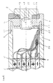
- the accumulator 1 has a housing consisting of two parts 2, 3, which are separated by the separator 4 separate positive electrodes 5 and negative electrodes 6 surrounds. When ready for operation, the accumulator 1 is filled in a known manner with an electrolyte, not shown in the figures.
- the housing is formed in two layers, consisting of a layer of a hard plastic 24 and a layer of a soft plastic 14.
- the soft plastic 14 shown hatched in a cross shape in the figures is fully welded to the hard plastic 24 shown hatched by oblique lines.
- the welded surface forms when the soft plastic 14 is injected along its contact surface with the hard plastic 24.
- the soft plastic 14 has an adjustable hardness by adding plasticizers or by selecting its degree of crosslinking, which is in the range known sealing materials.
- the hard plastic is adjusted in its hardness so that it achieves the usual housing strengths.
- Modified polyamides, styrene-ethylene-butylene-styrene copolymers and / or polypropylenes are used as materials.
- the plastic parts of the housing 2, 3 each have a circumferential overlapping area 9, 10, in which a flat contact occurs.
- the parts 9, 10 are held against one another by a circumferential ultrasonic weld seam 11.
- a volume 12 running along the circumference is formed above the overlapping area 9 and enclosed by the area 10, which volume is connected via a channel 13 to the volume of the soft plastic 14 in the area of the pole contacts 7, 8.
- This volume 12 is simultaneously filled during the spray welding of the soft plastic 14.
- the soft plastic 14 inside of the volume 12 is thus formed in one piece with the soft plastic 14 in the region of the pole contacts 7, 8 and is also welded over the entire surface to the hard plastic 24.
- the mechanical connection of the two housing parts 2, 3 is effected by latching elements 30, 31 arranged in the overlapping area 9, 10.
- a circumferential locking lug 31 of the one housing part 3 engages behind a circumferential groove 2 formed in the other housing part 2.
- a chamfer 32 of the locking lug 31 facilitates the joining of the two parts 2, 3.
- the soft plastic 14 is either fully connected to the two areas 9, 10 by spray welding within the volume 12 or is only connected to the area 10 by spray welding and the latching elements 30, 31 hold the area 9 in sealing contact with the soft plastic 14.
- Glass fibers or other known inert fibers are optionally embedded in the hard plastic 24.
- a volume fraction of the glass fiber of approximately 40% is preferred.
- a predetermined breaking point 15 is arranged as a thinned section.
- the predetermined breaking point 15 has a defined area and thickness, which are set so that an opening is formed within the accumulator housing from a certain excess pressure, which leads to pressure reduction.
- a through opening 16 is preferably arranged in the vicinity of the positive pole contact 7 and has an essentially T-shaped profile. This opening 16 is closed after filling with a T-shaped plug 17.
- a first embodiment contains pole contacts 7, 8 with a frustoconical bushing 18 which is overlapped by a cup-shaped pole cap 19.
- the frusto-conical bushing 18 lies flat against the hard plastic 24 with its laterally widened edge and is self-centered in a likewise frustoconical passage opening 20.
- the cup-shaped pole cap 19 is connected to the bushing 18 by spot welding and engages over the soft plastic 14 in a sealing arrangement.
- One or more welding spots 21 can be attached both before the injection of the soft plastic 14 and afterwards. In the latter case, the thermal energy introduced during welding is selected in a known manner so that plastic deformation of the soft plastic 14 and of the hard plastic 24 forming the through opening 20 is excluded.
- the pole contacts 7, 8 have an essentially T-shaped cross section, the radially widened region of which represents the pole caps 19 and merges in one piece into the bushing 18.
- the bushing 18 has a cylindrically hollowed interior 22 which forms a cup rivet and allows the end 23 to be flanged.
- the flanged end 23 engages behind a part of the hard plastic 24 in the area of the pole contacts 7, 8.
- the pole cap 19 is permanently pressed into the soft plastic 14 in sealing contact.
- an electrically conductive tab 25 made of metal is inserted between the flanged end 23 and the hard plastic 24, each of which creates a connection to the electrodes 5, 6.
- the tab 25 is connected by a welding spot 26 to terminal lugs 27, 28 protruding laterally from the electrodes.
- the electrodes 5, 6 are each arranged in layers one above the other, as shown in FIGS. 2 and 3.
- the electrodes 5, 6 as shown in Fig. 6, folded meandering with the separator 4 interposed.
- the electrode carrier of the positive electrode 5 is connected directly to the bushing 18, while the bushing 18 of the negative pole contact 8 is connected directly to the negative electrode 6 or one with the negative one Electrode 6 in contact strips 29 is connected.
- the electrodes 5, 6 can first be attached to the pole contacts 7, 8 and a housing part 3 during manufacture with their connecting lugs 27, 28.
- Such an accumulator assembly is shown in FIG. 5, the pole contacts 7, 8 already being sealed within the soft plastic 14 and the hard plastic 24.
- Such an assembly can be connected to the housing part 2 shown in the figures as well as inserted into a corresponding housing of an electrical device.
- the accumulator 1 then forms part of the device housing of the electrical device with its housing.
Landscapes
- Chemical & Material Sciences (AREA)
- Chemical Kinetics & Catalysis (AREA)
- Electrochemistry (AREA)
- General Chemical & Material Sciences (AREA)
- Sealing Battery Cases Or Jackets (AREA)
- Gas Exhaust Devices For Batteries (AREA)
- Supply Devices, Intensifiers, Converters, And Telemotors (AREA)
- Secondary Cells (AREA)
- Connection Of Batteries Or Terminals (AREA)
- Table Devices Or Equipment (AREA)
- Cell Separators (AREA)
- Filling Or Discharging Of Gas Storage Vessels (AREA)
Description
- Die Erfindung betrifft einen Akkumulator gemäß dem Oberbegriff des Anspruchs 1.
- Derartige Akkumulatoren sind in einer Vielzahl von Gehäuseformen bekannt. Ein herkömmlicher alkalischer Akkumulator weist ein zylindrisches Gehäuse auf, das aus Metall besten und einen topfförmigen elektrolytbefüllten Behälter sowohl für die Elektroden als auch den Separator bildet. Der den positiven Polkontakt haltende Deckel ist in die Topföffnung eingesetzt. Hierbei bildet der umgebördelte Rand eine sowohl gas- als auch flüssigkeitsdichte Halterung. Bei unrunden, insbesondere bei rechteckförmigen Zellen ist ein derartiges Metallgehäuse jedoch schwierig zu fertigen.
- Die Verwendung von Kunststoffgehäusen ist für Blei-Säure-Akkumulatoren bekannt und ermöglicht die Fertigung rechteckiger Gehäuse bei guter Raunausnutzung. Dieser Aufbau ist jedoch nicht auf alle Akkumulatorentypen übertragbar. Die in das Kunststoffgehäuse eingegossenen metallischen Polkontakze oder deren metallische Durchführungen weisen andere thermische Ausdehnungskoeffizienten als der Kunststoff auf und dürfen dennoch bei Erwärmung während des Ladens oder Entladens mit hohen Strömen nicht undicht werden. Während der gesamten Lebensdauer des Akkumulators muß sicherstellen sein, daß weder Gas noch Elektrolyt ungewollt austritt. Akkumulatoren mit sehr geringem Innenwiderstand, wie z.B. alkalische Nickel-Cadmium- oder Nickel-Metallhydrid-Akkumulatoren können unter hoher Strombelastung stark erhöhte Innendrucke aufbauen, die im Bereich der Polkontakte nicht zu Undichtigkeiten führen dürfen.
- Zwischen Gehäuse und Polkontakt eingelegte Dichtungen, wie z.B. die als O-Ringe bezeichneten elastischen Rundschnurringe, erfordern einen zusätzlichen Fertigungsschritt des Einlegens und korrekten Positionierens der Dichtung und tragen somit negativ zu den Herstellungskosten des Akkumulators bei. Schwierige Elektrolyten, die durch hohe Kapilarwirkung eine Neigung zum Unterkriechen von Dichtungen aufweisen, wie z.B. Kalilauge, die zusätzlich eine Wanderbewegung in Richtung des negativen Potentials zeigt, können bei nicht korrekt eingelegter Dichtung oder bei nachträglich mechanisch verschobener Dichtung aus dem Gehäuse austreten und in der Folge zu Schäden führen.
- Die EP-A1-0 089 619 beschreibt eine gas- und flüssigkeitsdichte Polabdichtung, die insbesondere für Bleiakkumulatoren, deren Gehäuse aus Kunststoff besteht, konstruiert ist. Zur Abdichtung wird ein aus mehreren Schichten verschiedener Materialien bestehendes Dichtungssystem vorgeschlagen, bei welchem unter anderem eine Freie Kammer den Polkontakt umgebend ausgebildet ist und Schmelzkleber sowie weitere Dichtungen an dieser Kammer angeordnet sind.
- Aus der US-PS 5 197 994 sind thermische Gehäuseverschweißungen von aus Kunststoff bestehenden Batteriegehäusen bekannt.
- Aus der EP-A2-0 538 039 ist eine eingelegte, aus einem Dichtungsmittel bestehende Kappe bekannt, die bei einer zylindrischen Batterie die mittlere Elektrode sowie den Polkontakt gegenüber dem Gehäuse hält und gleichzeitig eine Dichtung des Batteriegehäuses gegen austretende Fluide bildet.
- Demzufolge liegt der Erfindung die Aufgabe zugrunde, einen fertigungstechnisch günstig herstellbaren Akkumulator zu schaffen, der ein dauerhaft und zuverlässig dichtes Gehäuse aufweist, das in seiner Formgebung nicht eingeschränkt ist.
- Diese Aufgabe wird durch die Merkmale des Anspruchs 1 gelöst.
- Die Herstellung des Gehäuses im Bereich der Polkontakte aus einem weichen und einem harten Kunststoff, die miteinander festverbunden sind, gestattet es, den weichen Kunststoff als Dichtung für die Polkontakte und/oder die Durchführungen der Polkontake zu verwenden. Hierbei kann durch die mechanische Verbindung beider Kunststoffe ein Verschieben der Dichtung durch äußere Einflüsse verhindert werden. Dieser Aufbau führt ebenfalls dazu, daß im wesentlichen nur noch eine Dichtfläche, nämlich die Dichtfläche zwischen dem weichen Kunststoff und dem Polkontakz und/oder dessen Durchführung vorhanden ist. Der Elektrolyt oder das von diesem entwickelte Gas kann somit nicht mehr entlang einer zweiten Dichtfläche zwischen Dichtung und Gehäuse entweichen. Darüber hinaus läßt sich eine dichtende Anlage des weichen Kunststoffs am Polkontakt oder dessen Durchführung so gestalten, daß die Dichtfläche stark vergrößert ist und lange Strecken bei einem Austritt unterkrochen werden müssen.
- Fertigungstechnisch ist dieser Aufbau vorteilhaft, da nach dem Verbinden des weichen mit dem harten Kunststoff entsprechende Öffnungen für die Polkontakte z.B. durch Stanzen mit hoher Genauigkeit eingebracht werden können. Alternativ kann ein bereits im harten Kunststoff gehaltener Polkontakt oder dessen Durchführung nachträglich in einem Heiß-in-Heiß-Spritzschweißverfahren mit dem weichen Kunststoff umgeben werden. Es ergibt sich dabei jeweils eine vollflächige Verbindung des weichen mit dem harten Kunststoff.
- Da beide Kunststoffe im wesentlichen aus dem gleichen Thermoplast-Elastomer bestehen und sich entweder durch unterschiedliche Zugabe von Weichmachern oder durch unterschiedlichen Vernetzungsgrad in ihrer Härte unterscheiden, treten keine nachteiligen thermischen Spannungen auf. Die Wahl des Thermoplast-Elastomers gestattet es, chemisch inerte Materialien, wie z.B. modifizierte Polyamide, Styrol-Ethylen-Butylene-Styrol-Copolymere odere Polypropylene zu verwenden, die gegenüber dem Elektrolyten ausgezeichente Standfestigkeiten aufweisen.
- Derzeit zur Verfügung stehenden hochentwickelten Herstellungstechniken für Kunststofformteile, wie z.B. das Spritzschweißen, sind uneingeschränkt einsetzbar, wodurch eine Beschränkung der Gehäuseform nicht mehr gegeben ist.
- In einer bevorzugten Ausführungsform ist die Polkappe des Polkontaktes durch Punktschweißen mit dessen Durchführung verbunden und übergreift tassenartig einen Teil des weichen Kunststoffs. Hierdurch wird die Kriechstrecke unter der Dichtung um die Anlagefläche des weichen Kunststoffs an der Polkappe erhöht. Die Polkappe wird bei einer nachträglichen Anbringung an der Durchführung durch den weichen Kunststoff korrekt positioniert.
- Eine alternative Ausführungsform verwendet einen aus einem im wesentlichen tassenförmigen Niet bestehenden Polkontakt, dessen hinteres Ende bei der Fertigung so umgebördelt wird, daß es einen Teil des harten Kunststoffes hintergreift. Hierbei wird durch den umgebördelten Teil des Niets der vordere Bereich des Polkontaktes stets sicher in dichtender Anlage am weichen Kunststoff gehalten. In fertigungstechnisch günstiger Weise kann hierbei der umgebördelte Teil des Niets eine zwischen Niet und Gehäuse eingelegte leitfähige Lasche hintergreifen, die den elektrischen Kontakt zu den jeweiligen Elektroden herstellt. Somit läß sich kostengünstig in einem einzigen Arbeitsschritt durch Nieten sowohl der Polkontakt anbringen als auch dessen elektrische Verbindung herstellen.
- Eine weitere fertigungstechnische Verbesserung ergibt sich wenn das Gehäuse des Akkumulators zwischen zwei Gehäuseteilen ein umlaufendes Volumen enthält, das beim Spritzschweißen des weichen Kunststoffs gleichzeitig mitausgefüllt werden kann. Der weiche Kunststoff innerhalb dieses umlaufenden Volumens dient in vorteilhafter Weise als zusätzliche Gehäusedichtung, erfordert jedoch keinen eingenen Fertigungsschritt.
- Bestehen beide Gehäuseteile aus einem Kunstsstoff mit etwa gleicher Härte, können diese durch Ultraschallschweißen in einem überlappenden Bereich miteinander sicher und dauerhaft dicht verbunden werden.
- In alternativer Ausgestaltung sind beide Gehäuseteile durch in einem überlappenden Bereich angeordnete Rastelemente aneinander gehalten. Hierdurch können die Gehäuseteile in fertigungstechnisch günstiger Weise durch einfaches Zusammendrücken miteinander sicher verbunden werden. Wird der weiche Kunststoff nach dem Verrasten beider Gehäuseteile in das umlaufende Volumen eingebracht kommt es durch das Spritzschweißen in diesem Bereich zu einer vollflächigen und dichten Verbindung des weichen Kunststoffs mit dem harten Kunststoff beider Gehäuseteile. Werden beide Gehäuseteile nach dem Spritzschweißen des weichen Kunststoffs miteinander verrastet, wird durch die Rastelemente eine dichtende Anlage des harten Kunststoffs des einen Gehäuseteils am weichen Kunststoff des anderen Gehäuseteils gewährleistet.
- Durch Einbettung von Glasfasern in den Kunststoff, vorzugsweise mit einem Volumenanteil von etwa 40 %, lassen sich die mechanischen Eigenschaften des Gehäuses, wie seine Schlagfestigkeit, Bruch- und Biegebelastbarkeit deutlich verbessern.
- Mit einem rechteckigen Akkumulatorgehäuse, in dem die Elektroden schichtweise jeweils durch den Separator getrennt übereinander angordnet sind, lassen sich ungenutzte Volumenanteile vermeiden und es kann ein Akkumulator hoher Kapazität zur Verfügung gestellt werden.
- Bei gasdichten alkalischen Akkumulatoren, wie z.B. Nickel-Cadmium oder Nickel-Metallhydrid-Akkummulatoren, kann eine Sollbruchstelle als verdünnt ausgebildeter Abschnitt innerhalb des aus hartem Kunststoff bestehenden Gehäuseteils angeordnet werden. Hierdurch wird die Explosion des Akkumulators bei plötzlichem Anstieg des Innendrucks durch gezieltes Abgasen über die Sollbruchstelle verhindert.
- Ein nachträgliches Befüllen des Akkumulators mit dem Elektrolyten wird durch eine verschließbare Befüllungsöffnung ermöglicht. Die Anordnung der Befüllungsöffnung näher zum positiven als zum negativen Polkontakt vermindert die Kriechwirkung bei Einsatz von Kalilauge als Elektrolyt.
- In einer weiteren Ausführungsform stellt das Gehäuse des Akkumulators gleichzeitig auch einen Teil eines Gerätegehäuses eines elektrischen Gerätes dar. Hierdurch läßt sich beispielsweise die Konstruktion tragbarer Funktelefone vereinfachen und trotz eines Akkumulators hoher Kapazität deren Größe reduzieren.
- Die Erfindung wird nachstehend anhand der Zeichnungen im einzelnen beschrieben. Es zeigen:
- Fig. 1 einen teilweisen Querschnitt durch einen Akkumulator einer ersten erfindungsgemäßen Ausführungsform mit einer tassenförmigen Polkappe,
- Fig. 2 einen teilweisen Querschnitt durch einen Akkumulator einer zweiten erfindugnsgemäßen Ausführungsform mit einem nietartigen Polkontakt,
- Fig. 3 einen Querschnitt durch einen erfindugnsgemäßen Akkumulator mit rechteckigem Gehäuse und auf einer Gehäuseseite angeordneten Polkontakten,
- Fig. 4 einen Querschnitt durch den Akkumulator aus Fig. 3 entlang der Linie A-A,
- Fig. 5 eine an einem Gehäuseteil montierte Akkumulatoren-Baugruppe während eines Fertigungs-Zwischenschritts,
- Fig. 6 einen Querschnitt durch einen Akkumulator mit rechteckigem Gehäuse und auf zwei gegenüberliegenden Gehäuseseiten angeordneten Polkontakten,
- Fig. 7 einen Querschnitt durch den Akkumulator aus Fig. 6 entlang der Linie B-B.
- In den Figuren sind ähnliche oder gleiche Bestandteile verschiedener Ausführungsformen jeweils mit den selben Bezugszeichen versehen.
- Ohne Beschränkung der vielzähligen durch die Erfindung möglichen Bauformen wird nachstehend ein rechteckiger gas-und flüssigkeitsdichter alkalischer Akkumulator beschrieben. Als gas- und flüssigkeitsdicht werden dabei Akkumulatoren bezeichnet, die unter normalen Betriebsbedingungen weder Gase noch Flüssigkeiten austreten lassen, jedoch bei Erreichen vorbestimmter Bedingungen, wie z.B. einem vorgegebenen Überdruck, gezielt Öffnungen bilden können.
- Der Akkumulator 1 weist ein aus zwei Teilen 2, 3 bestehendes Gehäuse auf, das die durch den Separator 4 voneinander getrennten positiven Elektroden 5 und negativen Elektroden 6 umgibt. Im betriebsfertigen Zustand ist der Akkumulator 1 in bekannter Weise mit einem in den Figuren nicht dargestellten Elektrolyten befüllt.
- Im Bereich der Polkontakte 7, 8 ist das Gehäuse zweilagig, bestehend aus einer Lage eines harten Kunststoffs 24 und einer Lage eines weichen Kunststoffs 14 ausgebildet. Der in den Figuren kreuzförmig schraffiert dargestellte weiche Kunststoff 14 ist mit dem durch schräge Linien schraffiert dargestellten harten Kunststoff 24 vollflächig verschweißt.
- Bei dem verwendeten Heiß-in-Heiß-Spritzschweißen bildet sich die verschweißte Fläche beim Einspritzen des weichen Kunststoffs 14 entlang seiner Berührungsfläche zum harten Kunststoff 24. Der weiche Kunststoff 14 hat durch Beigabe von Weichmachern oder durch Wahl seines Vernetzungsgrades eine einstellbare Härte, die im Bereich bekannter Dichtungsmaterialien liegt. Der harte Kunststoff ist in seiner Härte so eingestellt, daß er die üblichen Gehäusefestigkeiten erreicht.
- Als Materialien werden modifizierte Polyamide, Styrol-Ethylen-Butylene-Styrol-Copolymere und/oder Polypropylene eingesetzt. Die aus Kunststoff bestehenden Teile des Gehäuses 2, 3 weisen jeweils einen über den Umfang verlaufenden überlappenden Bereich 9, 10 auf, in dem es zu einer flächigen Anlage kommt. Mit einer umlaufenden Ultraschallschweißnaht 11 sind die Teile 9, 10 aneinander gehalten.
- In weiterer erfindungsgemäßer Ausgestaltung ist oberhalb des überlappenden Bereichs 9 und vom Bereich 10 umschlossen ein entlang des Umfangs verlaufendes Volumen 12 ausgebildet, das über einen Kanal 13 mit dem Volumen des weichen Kunststoffs 14 im Bereich der Polkontakte 7, 8 verbunden. Dieses Volumen 12 wird beim Spritzschweißen des weichen Kunststoffs 14 gleichzeitig mitgefüllt. Der weiche Kunststoff 14 innerhalb des Volumens 12 ist somit einstückig mit dem weichen Kunststoff 14 im Bereich der Polkontakte 7, 8 ausgebildet und ebenfalls vollflächig mit dem harten Kunststoff 24 verschweißt.
- In alternativer Ausgestaltung wird die mechanische Verbindung beider Gehäuseteile 2, 3 durch in dem überlappenden Bereich 9, 10 angeordnete Rastelemente 30, 31 bewirkt. Hierbei hintergreift im verrasteten Zustand eine umlaufende Rastnase 31 des einen Gehäuseteils 3 eine im jeweils anderen Gehäuseteil 2 ausgebildtete umlaufende Nut 2. Durch eine Anlaufschräge 32 der Rastnase 31 ist das Zusammenfügen beider Teile 2, 3 erleichtert. Der weiche Kunststoff 14 ist innerhalb des Volumens 12 entweder mit beiden Bereichen 9, 10 durch Spritzschweißen vollflächig verbunden oder ist nur mit dem Bereich 10 durch Spritzschweißen verbunden und die Rastelemente 30, 31 halten den Bereich 9 in stirnseitig dichtender Anlage am weichen Kunststoff 14.
- In den harten Kunststoff 24 sind wahlweise Glasfasern oder andere bekannte inerte Fasern eingebettet. Hierbei wird ein Volumenanteil der Glasfaser von ca. 40 % bevorzugt.
- Innerhalb des aus hartem Kunststoff 24 bestehenden Gehäuseteils 2, 3 ist eine Sollbruchstelle 15 als verdünnt ausgebildeter Abschnitt anordnet. Die Sollbruchstelle 15 weist eine definierte Fläche und Dicke auf, die so eingestellt sind, daß ab einem bestimmten Überdruck innerhalb des Akkumulatorgehäuses eine Öffnung gebildet wird, die zum Druckabbau führt.
- Bei mit Kalilauge als Elektrolyten befüllten Akkumulatoren ist eine Durchgangsöffnung 16 vorzugsweise in der Nähe des positiven Polkontaktes 7 angeordnet und weist ein im wesentlichen T-förmiges Profil auf. Diese Öffnung 16 ist nach dem Befüllen mit einem T-förmigen Stopfen 17 verschlossen.
- Eine erste Ausführungsform enthält Polkontakte 7, 8 mit einer kegelstumpfförmigen Durchführung 18, die von einer tassenförmigen Polkappe 19 übergriffen wird. Die kegelstumpfförmige Durchführung 18 liegt mit ihrem seitlich erweiterten Rand flächig am harten Kunststoff 24 an und ist in einer ebenfalls kegelstumpfförmigen Durchgangsöffnung 20 selbstzentriert gehalten. Die tassenförmige Polkappe 19 ist durch Punktschweißen mit der Durchführung 18 verbunden und übergreift den weichen Kunststoff 14 in dichtender Anlage. Ein oder mehrere Schweißpunkte 21 können sowohl vor dem Einspritzen des weichen Kunststoffs 14 als auch danach angebracht werden. In bekannter Weise ist in letzterem Fall die beim Schweißen eingebrachte thermische Energie so gewählt, daß eine plastische Verformung des weichen Kunststoffs 14 sowie des die Durchgangsöffnung 20 bildenden harten Kunststoffs 24 ausgeschlossen ist.
- In einer alternativen Ausführungsform haben die Polkontakte 7, 8 einen im wesentlichen T-förmigen Querschnitt, dessen radial erweiterter Bereich die Polkappen 19 darstellt und einstückig in die Durchführung 18 übergeht. Die Durchführung 18 weist einen zylindrisch ausgehöhlten Innenraum 22 auf, der einen Tassenniet bildet und das Umbördeln des Endes 23 gestattet. Das umgebördelte Ende 23 hintergreift einen Teil des harten Kunststoffs 24 im Bereich der Polkontakte 7, 8. Hierdurch ist die Polkappe 19 in dichtender Anlage in den weichen Kunststoff 14 dauerhaft eingepreßt.
- In weiterer Ausgestaltung ist zwischen dem umgebördelten Ende 23 und dem harten Kunststoff 24 eine aus Metall bestehende elektrisch leitfähige Lasche 25 eingelegt, die jeweils eine Verbindung mit den Elektroden 5, 6 herstellt. Durch einen Schweißpunkt 26 ist die Lasche 25 mit seitlich von den Elektroden hervorstehenden Anschlußfahnen 27, 28 verbunden. In dem Gehäuse 2, 3 des Akkumulators 1 sind die Elektroden 5, 6 jeweils schichtweise übereinander, wie in den Fig. 2 und 3 dargestellt, angeordnet. Alternativ sind die Elektroden 5, 6 wie in Fig. 6 gezeigt, meanderförmig unter Zwischenlage des Separators 4 übereinander gefaltet.
- Bei dieser Ausführungsform, die vorzugsweise an gegenüberliegenden Gehäuseseiten jeweils einen Polkontakt 7, 8 enthält, ist der Elektrodenträger der positiven Elektrode 5 direkt mit der Durchführung 18 verbunden, während die Durchführung 18 des negativen Polkontaktes 8 direkt mit der negativen Elektrode 6 oder einem mit der negativen Elektrode 6 in Kontakt stehenden Streifen 29 verbunden ist.
- Aufgrund des zweiteiligen Gehäuseaufbaus können die Elektroden 5, 6 während der Fertigung zunächst mit ihren Anschlußfahnen 27, 28 an dem Polkontakten 7, 8 und einem Gehäuseteil 3 befestigt werden. Eine solche Akkumulatoren-Baugruppe ist in Fig. 5 dargestellt, wobei die Polkontakte 7, 8 bereits innerhalb des weichen Kunststoffs 14 und des harten Kunststoffs 24 dichtend gehalten sind.
- Eine derartige Baugruppe kann sowohl mit dem in den Figuren dargestellten Gehäuseteil 2 verbunden werden als auch in ein entsprechendes Gehäuse eines Elektrogerätes eingesetzt werden. Der Akkumulator 1 bildet dann mit seinem Gehäuse einen Teil des Gerätegehäuses des elektrischen Gerätes.
Claims (15)
- Akkumulator miteinem gas- und flüssigkeitsdichten, elektrolytbefüllten Gehäuse,in dem durch einen Separator voneinander getrennte Elektroden angeordnet sind, die jeweils mit von der Außenseite des Gehäuses zugänglichen Polkontakten elektrisch verbunden sind, dadurch gekennzeichnet, daßdas Gehäuse (2, 3) im Bereich der Polkontakte (7, 8) aus einem weichen Kunststoff (14) und einem harten Kunststoff (24) besteht, die miteinander fest verbunden sind,wobei der weiche Kunststoff (14) eine Dichtung für die Polkontakte (7, 8) und/oder die Durchführungen (18) der Polkontakte (7, 8) bildet.
- Akkumulator nach Anspruch 1,
dadurch gekennzeichnet, daß
der weiche Kunststoff (14) und der harte Kunststoff (24) des Gehäuses (2, 3) vollflächig miteinander durch Spritzschweißen verbunden sind. - Akkumulator nach Anspruch 1 oder 2,
dadurch gekennzeichnet, daß
der weiche Kunststoff (14) und der harte Kunststoff (24) aus einem Thermoplast-Elastomer, insbesondere aus einem modifizierten Polyamid, einem Styrol-Ethylen-Butylene-Styrol-Copolymer, und/oder einem Polypropylen bestehen. - Akkumulator nach Anspruch 1, 2, oder 3,
dadurch gekennzeichnet, daß
die Polkappe (19) des Polkontakts (7, 8) durch Punktschweißen mit der Durchführung (18) verbunden ist und tassenartig einen Teil des weichen Kunststoffs (14) übergreifft. - Akkumulator nach Anspruch 1, 2, oder 3,
dadurch gekennzeichnet, daß
die Durchführung (18) des Polkontaktes einen im wesentlichen tassenförmigen Niet bildet, dessen umgebördeltes Ende (23) einen Teil des harten Kunststoffes (24) so hintergreift, daß der Polkontakt (7, 8) und/oder dessen Durchführung (18) in dichtender Anlage am weichen Kunststoff (14) gehalten ist. - Akkumulator nach Anspruch 5,
dadurch gekennzeichnet, daß
das umgebördelte Ende (23) des Niet eine zwischen Niet und Gehäuse eingelegte leitfähige Lasche (25) hintergreift. - Akkumulator nach einem der vorstehenden Ansprüche,
dadurch gekennzeichnet, daß
das Gehäuse (2, 3) ein zwischen zwei Gehäuseteilen (2, 3) umlaufendes Volumen (12) enthält, das mit dem weichen Kunststoff als Dichtung ausgefüllt ist. - Akkumulator nach Anspruch 7,
dadurch gekennzeichnet, daß
der weiche Kunststoff (14) innerhalb des Volumens (12) und der weiche Kunststoff (14) im Bereich der Polkontakte (7, 8) miteinander verbunden sind. - Akkumulator nach einem der vorstehenden Ansprüche,
dadurch gekennzeichnet,daß
das Gehäuse (2, 3) vollständig aus Kunststoff (14, 24) besteht und die beiden Gehäuseteile (2, 3) durch Ultraschallschweißen in einem überlappenden Bereich (9, 10) miteinander verbunden sind. - Akkumulator nach einem der Ansprüche 1 bis 8,
dadurch gekennzeichnet,daß
das Gehäuse (2, 3) vollständig aus Kunststoff (14, 24) besteht und die beiden Gehäuseteile (2, 3) durch in einem überlappenden Bereich (9, 10) angeordnete Rastelemente (30, 31) miteinander verbunden sind. - Akkumulator nach einem der vorstehenden Ansprüche,
dadurch gekennzeichnet,daß
in den harten Kunststoff (24) Glasfasern eingebettet sind. - Akkumulator nach einem der vorstehenden Ansprüche,
dadurch gekennzeichnet, daß
das Gehäuse (2, 3) prismatisch, insbesondere rechteckig, ist und die Elektroden (5, 6) schichtweise jeweils durch den Separator (4) getrennt übereinander angeordnet sind, wobei hinter den Polkontakten (7, 8) angeordnete von den Elektroden (5, 6) seitlich hervostehende Anschlußfahnen (27, 28) miteinander und mit dem jeweiligen Polkontakt (7, 8), vorzugsweise durch Punktschweißen, elektrisch verbunden sind. - Akkumulator nach einem der vorstehenden Ansprüche,
dadurch gekennzeichnet, daß
eine Sollbruchstelle (15) als verdünnt ausgebildeter Abschnitt innerhalb des aus hartem Kunstststoff (24) bestehenden Teils des Gehäuses (2, 3) angeordnet ist. - Akkumulator nach einem der vorstehenden Ansprüche,
dadurch gekennzeichnet, daß
das Gehäuse (2, 3) eine Befüllungsöffnung (16) aufweist, die mit geringerem Abstand zum positiven Polkontakt (7) als zum negativen Polkontakt (8) angeordnet ist und mit einem im Profil T-förmigen Stopfen (17) verschlossen ist. - Akkumulator nach einem der vorstehenden Ansprüche,
dadurch gekennzeichnet, daß
das Gehäuse (2, 3) des Akkumulators (1) einen Teil eines Gerätegehäuses eines elektrischen Gerätes bildet.
Applications Claiming Priority (3)
| Application Number | Priority Date | Filing Date | Title |
|---|---|---|---|
| DE4325464 | 1993-07-29 | ||
| DE4325464A DE4325464A1 (de) | 1993-07-29 | 1993-07-29 | Akkumulator mit Kunststoffgehäuse |
| PCT/DE1994/000836 WO1995004380A1 (de) | 1993-07-29 | 1994-07-16 | Akkumulator mit kunststoffgehäuse |
Publications (2)
| Publication Number | Publication Date |
|---|---|
| EP0711459A1 EP0711459A1 (de) | 1996-05-15 |
| EP0711459B1 true EP0711459B1 (de) | 1996-12-27 |
Family
ID=6493997
Family Applications (2)
| Application Number | Title | Priority Date | Filing Date |
|---|---|---|---|
| EP94921575A Expired - Lifetime EP0711459B1 (de) | 1993-07-29 | 1994-07-16 | Akkumulator mit kunststoffgehäuse |
| EP94920892A Expired - Lifetime EP0711460B1 (de) | 1993-07-29 | 1994-07-16 | Gasdichter alkalischer akkumulator mir ventilbaugruppe |
Family Applications After (1)
| Application Number | Title | Priority Date | Filing Date |
|---|---|---|---|
| EP94920892A Expired - Lifetime EP0711460B1 (de) | 1993-07-29 | 1994-07-16 | Gasdichter alkalischer akkumulator mir ventilbaugruppe |
Country Status (16)
| Country | Link |
|---|---|
| US (2) | US5789096A (de) |
| EP (2) | EP0711459B1 (de) |
| JP (2) | JPH09501006A (de) |
| KR (1) | KR100309451B1 (de) |
| CN (2) | CN1128084A (de) |
| AT (2) | ATE150905T1 (de) |
| AU (2) | AU7225794A (de) |
| CA (2) | CA2168101A1 (de) |
| DE (3) | DE4325464A1 (de) |
| DK (2) | DK0711460T3 (de) |
| ES (2) | ES2100725T3 (de) |
| FI (2) | FI960373A7 (de) |
| GR (2) | GR3022958T3 (de) |
| NO (2) | NO960214L (de) |
| RU (2) | RU2123742C1 (de) |
| WO (2) | WO1995004381A1 (de) |
Families Citing this family (28)
| Publication number | Priority date | Publication date | Assignee | Title |
|---|---|---|---|---|
| US5865727A (en) * | 1995-08-25 | 1999-02-02 | Asahi Kogaku Kogyo Kabushiki Kaisha | Portable endoscope system |
| DE19544050A1 (de) * | 1995-11-25 | 1997-05-28 | Emmerich Christoph Gmbh Co Kg | Verfahren zur Herstellung von prismatischen alkalischen Akkumulatorzellen |
| KR100467426B1 (ko) * | 1997-08-06 | 2005-05-03 | 삼성에스디아이 주식회사 | 리튬폴리머계열전지의밀봉용기 |
| SE9704684L (sv) * | 1997-12-16 | 1999-06-17 | Ni Me Hydrid Ab | Behållare för en battericell |
| KR100553729B1 (ko) * | 1999-01-22 | 2006-02-17 | 삼성에스디아이 주식회사 | 이차전지의 외장 케이스 |
| US6265104B1 (en) | 1999-08-13 | 2001-07-24 | The Gillette Company | Hot-melt seal for metal-air battery |
| RU2190894C2 (ru) * | 2000-01-17 | 2002-10-10 | Вишневский Александр Евгеньевич | Конденсатор с двойным электрическим слоем (варианты) |
| US6641949B2 (en) | 2001-04-19 | 2003-11-04 | Zinc Matrix Power, Inc. | Battery vent and method of assembly |
| ITVI20010240A1 (it) * | 2001-11-14 | 2003-05-14 | Franco Stocchiero | Gruppo valvolare di tenuta e di sfiato per accumulatori elettrici |
| DE10300008B4 (de) * | 2002-01-09 | 2006-04-27 | Nec Tokin Tochigi Ltd., Utsunomiya | Verschlossene Batterie und Verfahren zur Herstellung einer verschlossenen Batterie |
| US20040137321A1 (en) * | 2002-11-27 | 2004-07-15 | Jean-Francois Savaria | Casing for an energy storage device |
| RU2251762C2 (ru) * | 2002-12-04 | 2005-05-10 | Открытое акционерное общество "Научно-исследовательский проектно-конструкторский и технологический институт стартерных аккумуляторов" (ОАО "НИИСТА") | Ручка свинцовых батарей |
| US6991872B2 (en) * | 2003-03-26 | 2006-01-31 | The Gillette Company | End cap seal assembly for an electrochemical cell |
| KR100591421B1 (ko) * | 2004-09-07 | 2006-06-21 | 삼성에스디아이 주식회사 | 형상기억 안전벤트를 갖는 리튬 이온 이차 전지 |
| RU2296394C1 (ru) * | 2005-06-14 | 2007-03-27 | Закрытое акционерное общество "ЭЛЕКТРОТЯГА" | Герметизированный свинцовый аккумулятор |
| EP1742323A1 (de) * | 2005-07-05 | 2007-01-10 | Sony Ericsson Mobile Communications AB | Überdruckventil für einen Batterielader |
| CN101488566B (zh) * | 2008-01-15 | 2011-08-17 | 财团法人工业技术研究院 | 软包装电池及其气密式导电联接结构与组装方法 |
| RU2376688C2 (ru) * | 2008-02-14 | 2009-12-20 | Открытое акционерное общество "УРАЛЬСКИЙ ЭЛЕКТРОХИМИЧЕСКИЙ КОМБИНАТ" | Способ соединения электродов химического источника тока в полублоки |
| EP2412043A2 (de) * | 2009-03-27 | 2012-02-01 | Johnson Controls Saft Advanced Power Solutions LLC | Batteriemodul mit abgedichteter entlüftungskammer |
| JP5531478B2 (ja) * | 2009-07-16 | 2014-06-25 | 日産自動車株式会社 | バッテリーパック |
| JP5585174B2 (ja) * | 2010-04-07 | 2014-09-10 | 日産自動車株式会社 | 電解液注液方法および電解液注液装置 |
| US20120225331A1 (en) * | 2011-03-02 | 2012-09-06 | Lithionics, Llc | Battery pack protection system |
| FR2997559B1 (fr) * | 2012-10-31 | 2016-12-09 | Renault Sa | Enveloppe de protection thermique de batterie pour vehicule automobile |
| DE102012222836A1 (de) * | 2012-12-12 | 2014-06-12 | Robert Bosch Gmbh | Gehäuse für einen gasdichten Akkumulator |
| KR101485897B1 (ko) * | 2013-10-29 | 2015-01-26 | 주식회사 비츠로셀 | 내충격성 효율을 높인 비축전지 |
| CN112421154A (zh) * | 2020-10-20 | 2021-02-26 | 浙江南都电源动力股份有限公司 | 一种锂电池顶盖组件、锂电池及其制备方法 |
| CN115995654B (zh) * | 2023-02-03 | 2025-07-08 | 楚能新能源股份有限公司 | 一种圆柱电芯 |
| WO2025047080A1 (ja) * | 2023-08-29 | 2025-03-06 | パナソニックIpマネジメント株式会社 | 電池 |
Family Cites Families (19)
| Publication number | Priority date | Publication date | Assignee | Title |
|---|---|---|---|---|
| BE755411A (fr) * | 1969-08-27 | 1971-03-01 | Union Carbide Corp | Soupape de surete pour recipient scelle etanche aux fluides et specialement pour cellule galvanique alcaline |
| SU611264A1 (ru) * | 1973-03-09 | 1978-06-15 | Ленинградский Аккумуляторный Завод "Ленинская Искра" | Электрический аккумул тор |
| FR2292344A1 (fr) * | 1974-11-19 | 1976-06-18 | Europ Accumulateurs | Procede de montage d'une batterie d'accumulateurs |
| FR2359517A1 (fr) * | 1976-07-20 | 1978-02-17 | Europ Accumulateurs | Perfectionnements aux accumulateurs et batteries d'accumulateurs electriques |
| US4215187A (en) * | 1977-09-23 | 1980-07-29 | Varta Batterie Aktiengesellschaft | Gas-tight galvanic cell |
| DE2757568C2 (de) * | 1977-12-23 | 1986-05-15 | Varta Batterie Ag, 3000 Hannover | Elektrischer Akkumulator |
| US4328289A (en) * | 1980-09-26 | 1982-05-04 | Union Carbide Corporation | Electrochemical cell having a resealable vent closure |
| US4532705A (en) * | 1980-09-26 | 1985-08-06 | Union Carbide Corporation | Method of making an electrochemical cell having a resealable vent closure |
| GB2117198A (en) * | 1982-03-19 | 1983-10-05 | Philips Electronic Associated | Frequency synthesiser |
| DE3210159C2 (de) * | 1982-03-19 | 1984-02-09 | Accumulatorenfabrik Sonnenschein GmbH, 6470 Büdingen | Gas- und flüssigkeitsdichte Polabdichtung |
| JPS62147652A (ja) * | 1985-12-23 | 1987-07-01 | Matsushita Electric Ind Co Ltd | 密閉形鉛蓄電池 |
| US4780378A (en) * | 1987-09-02 | 1988-10-25 | General Motors Corporation | Battery vent valve |
| US4859547A (en) * | 1987-10-06 | 1989-08-22 | Gates Energy Products, Inc. | Battery terminal and method |
| DE3742026A1 (de) * | 1987-12-11 | 1989-06-22 | Varta Batterie | Kunststoffdichtungselement fuer galvanische primaerelemente |
| US5080983A (en) * | 1990-08-16 | 1992-01-14 | Minnesota Mining And Manufacturing Company | Battery |
| US5197994A (en) * | 1990-11-26 | 1993-03-30 | Daniell Battery Manufacturing Co., Inc. | Method of heat sealing a battery |
| US5171647A (en) * | 1990-12-10 | 1992-12-15 | Ovonic Battery Company, Inc. | Hydrogen containment cover assembly for sealing the cell can of a rechargeable electrochemical hydrogen storage cell |
| US5227261A (en) * | 1991-10-15 | 1993-07-13 | Eveready Battery Company, Inc. | Cylindrical electrochemical cells with a diaphragm seal |
| US5229223A (en) * | 1991-10-29 | 1993-07-20 | Eveready Battery Company, Inc. | Air-assisted alkaline cell having a multilayer film seal assembly |
-
1993
- 1993-07-29 DE DE4325464A patent/DE4325464A1/de not_active Withdrawn
-
1994
- 1994-07-16 US US08/586,763 patent/US5789096A/en not_active Expired - Fee Related
- 1994-07-16 DK DK94920892.0T patent/DK0711460T3/da active
- 1994-07-16 RU RU96105401/09A patent/RU2123742C1/ru not_active IP Right Cessation
- 1994-07-16 AU AU72257/94A patent/AU7225794A/en not_active Abandoned
- 1994-07-16 AU AU71824/94A patent/AU7182494A/en not_active Abandoned
- 1994-07-16 WO PCT/DE1994/000835 patent/WO1995004381A1/de not_active Ceased
- 1994-07-16 DK DK94921575.0T patent/DK0711459T3/da active
- 1994-07-16 ES ES94920892T patent/ES2100725T3/es not_active Expired - Lifetime
- 1994-07-16 JP JP7505475A patent/JPH09501006A/ja active Pending
- 1994-07-16 EP EP94921575A patent/EP0711459B1/de not_active Expired - Lifetime
- 1994-07-16 US US08/586,775 patent/US5783329A/en not_active Expired - Fee Related
- 1994-07-16 JP JP7505474A patent/JPH09501005A/ja active Pending
- 1994-07-16 RU RU96103654/09A patent/RU2125754C1/ru not_active IP Right Cessation
- 1994-07-16 DE DE59402248T patent/DE59402248D1/de not_active Expired - Fee Related
- 1994-07-16 CN CN94192900A patent/CN1128084A/zh active Pending
- 1994-07-16 WO PCT/DE1994/000836 patent/WO1995004380A1/de not_active Ceased
- 1994-07-16 KR KR1019960700424A patent/KR100309451B1/ko not_active Expired - Fee Related
- 1994-07-16 CN CN94192902A patent/CN1064179C/zh not_active Expired - Fee Related
- 1994-07-16 EP EP94920892A patent/EP0711460B1/de not_active Expired - Lifetime
- 1994-07-16 AT AT94920892T patent/ATE150905T1/de not_active IP Right Cessation
- 1994-07-16 DE DE59401425T patent/DE59401425D1/de not_active Expired - Fee Related
- 1994-07-16 FI FI960373A patent/FI960373A7/fi unknown
- 1994-07-16 FI FI960372A patent/FI960372A0/fi unknown
- 1994-07-16 ES ES94921575T patent/ES2098971T3/es not_active Expired - Lifetime
- 1994-07-16 AT AT94921575T patent/ATE146901T1/de not_active IP Right Cessation
- 1994-07-16 CA CA002168101A patent/CA2168101A1/en not_active Abandoned
- 1994-07-16 CA CA002168100A patent/CA2168100A1/en not_active Abandoned
-
1996
- 1996-01-17 NO NO960214A patent/NO960214L/no not_active Application Discontinuation
- 1996-01-17 NO NO960213A patent/NO960213L/no not_active Application Discontinuation
-
1997
- 1997-03-27 GR GR970400633T patent/GR3022958T3/el unknown
- 1997-05-05 GR GR970400991T patent/GR3023334T3/el unknown
Also Published As
Similar Documents
| Publication | Publication Date | Title |
|---|---|---|
| EP0711459A1 (de) | Akkumulator mit kunststoffgehäuse | |
| DE102010027699B4 (de) | Batterie | |
| DE69119585T2 (de) | Elektrochemische zelle mit verbesserter einfüllöffnung | |
| DE69612537T2 (de) | Gas- und flüssigkeitsdichte Abdichtung des metallischen Poles einer dichten Sekundärzelle | |
| DE60318243T2 (de) | Bipolarbatterie und verfahren zur herstellung einer bipolarbatterie | |
| DE69501755T2 (de) | Gasdichter Akkumulator und Verfahren zu seiner Herstellung | |
| DE69527735T2 (de) | Sicherheitsanordnung für Batterie | |
| DE69815288T2 (de) | Sicherheitsentlüftung für Akkumulator oder Batterie | |
| DE69023784T2 (de) | Zylindrische Batterie mit organischem Elektrolyten und PTC-Vorrichtung. | |
| DE102004054821B4 (de) | Batteriemodul | |
| DE69206426T2 (de) | Verschlussanordnung für alkalische Batterie. | |
| WO2008058758A1 (de) | Batteriezelle mit kontaktelementanordnung | |
| DE3838575A1 (de) | Elektrische zelle | |
| DE102015108530A1 (de) | Zusammengesetzte Batterie | |
| DE1671925A1 (de) | Elektrochemischer Generator mit einem zylinderringfoermigen Gehaeuse | |
| EP1139464B1 (de) | Alkalischer Akkumulator | |
| DE2941757A1 (de) | Verschlussanordnung fuer galvanische elemente | |
| DE69209318T2 (de) | Zylindrische zelle mit verbesserter verschlussanordnung | |
| WO2015162001A2 (de) | Anordnung mehrerer in einem gehäuse gestapelter galvanischer elemente und batterie umfassend eine solche anordnung galvanischer elemente | |
| DE102014219001A1 (de) | Batteriezelle mit Zellengehäuse und einer Deckelanordnung mit Batteriekontakten | |
| EP4087028A1 (de) | Sekundärbatterie | |
| DE2527576A1 (de) | Dichter elektrochemischer generator | |
| DE102008059958B4 (de) | Einzelzelle und Batterie mit einer Mehrzahl elektrisch seriell und/oder parallel miteinander verbundener Einzelzellen | |
| DE102013203037A1 (de) | Batteriezelle mit wenigstens einem eine Öffnung aufweisenden Anschlusspol und Verfahren zur Herstellung einer Batteriezelle | |
| DE102014018748A1 (de) | Einzelzelle und Verfahren zur Herstellung einer solchen |
Legal Events
| Date | Code | Title | Description |
|---|---|---|---|
| PUAI | Public reference made under article 153(3) epc to a published international application that has entered the european phase |
Free format text: ORIGINAL CODE: 0009012 |
|
| 17P | Request for examination filed |
Effective date: 19960123 |
|
| AK | Designated contracting states |
Kind code of ref document: A1 Designated state(s): AT BE CH DE DK ES FR GB GR IE IT LI LU NL PT SE |
|
| GRAG | Despatch of communication of intention to grant |
Free format text: ORIGINAL CODE: EPIDOS AGRA |
|
| GRAH | Despatch of communication of intention to grant a patent |
Free format text: ORIGINAL CODE: EPIDOS IGRA |
|
| 17Q | First examination report despatched |
Effective date: 19960522 |
|
| GRAH | Despatch of communication of intention to grant a patent |
Free format text: ORIGINAL CODE: EPIDOS IGRA |
|
| ITF | It: translation for a ep patent filed | ||
| GRAA | (expected) grant |
Free format text: ORIGINAL CODE: 0009210 |
|
| AK | Designated contracting states |
Kind code of ref document: B1 Designated state(s): AT BE CH DE DK ES FR GB GR IE IT LI LU NL PT SE |
|
| REF | Corresponds to: |
Ref document number: 146901 Country of ref document: AT Date of ref document: 19970115 Kind code of ref document: T |
|
| REG | Reference to a national code |
Ref country code: CH Ref legal event code: NV Representative=s name: BOVARD AG PATENTANWAELTE |
|
| REF | Corresponds to: |
Ref document number: 59401425 Country of ref document: DE Date of ref document: 19970206 |
|
| REG | Reference to a national code |
Ref country code: IE Ref legal event code: FG4D Free format text: 71302 |
|
| ET | Fr: translation filed | ||
| REG | Reference to a national code |
Ref country code: ES Ref legal event code: FG2A Ref document number: 2098971 Country of ref document: ES Kind code of ref document: T3 |
|
| GBT | Gb: translation of ep patent filed (gb section 77(6)(a)/1977) |
Effective date: 19970411 |
|
| REG | Reference to a national code |
Ref country code: GR Ref legal event code: FG4A Free format text: 3022958 |
|
| REG | Reference to a national code |
Ref country code: DK Ref legal event code: T3 |
|
| REG | Reference to a national code |
Ref country code: PT Ref legal event code: SC4A Free format text: AVAILABILITY OF NATIONAL TRANSLATION Effective date: 19970327 |
|
| PLBE | No opposition filed within time limit |
Free format text: ORIGINAL CODE: 0009261 |
|
| STAA | Information on the status of an ep patent application or granted ep patent |
Free format text: STATUS: NO OPPOSITION FILED WITHIN TIME LIMIT |
|
| 26N | No opposition filed | ||
| PGFP | Annual fee paid to national office [announced via postgrant information from national office to epo] |
Ref country code: SE Payment date: 20000721 Year of fee payment: 7 Ref country code: FR Payment date: 20000721 Year of fee payment: 7 |
|
| PGFP | Annual fee paid to national office [announced via postgrant information from national office to epo] |
Ref country code: GB Payment date: 20000724 Year of fee payment: 7 Ref country code: BE Payment date: 20000724 Year of fee payment: 7 |
|
| PGFP | Annual fee paid to national office [announced via postgrant information from national office to epo] |
Ref country code: NL Payment date: 20000725 Year of fee payment: 7 Ref country code: LU Payment date: 20000725 Year of fee payment: 7 |
|
| PGFP | Annual fee paid to national office [announced via postgrant information from national office to epo] |
Ref country code: ES Payment date: 20000726 Year of fee payment: 7 Ref country code: AT Payment date: 20000726 Year of fee payment: 7 |
|
| PGFP | Annual fee paid to national office [announced via postgrant information from national office to epo] |
Ref country code: DK Payment date: 20000728 Year of fee payment: 7 |
|
| PGFP | Annual fee paid to national office [announced via postgrant information from national office to epo] |
Ref country code: GR Payment date: 20000731 Year of fee payment: 7 |
|
| PGFP | Annual fee paid to national office [announced via postgrant information from national office to epo] |
Ref country code: DE Payment date: 20000802 Year of fee payment: 7 Ref country code: CH Payment date: 20000802 Year of fee payment: 7 |
|
| PGFP | Annual fee paid to national office [announced via postgrant information from national office to epo] |
Ref country code: PT Payment date: 20000809 Year of fee payment: 7 |
|
| PGFP | Annual fee paid to national office [announced via postgrant information from national office to epo] |
Ref country code: IE Payment date: 20000814 Year of fee payment: 7 |
|
| PG25 | Lapsed in a contracting state [announced via postgrant information from national office to epo] |
Ref country code: LU Free format text: LAPSE BECAUSE OF NON-PAYMENT OF DUE FEES Effective date: 20010716 Ref country code: IE Free format text: LAPSE BECAUSE OF NON-PAYMENT OF DUE FEES Effective date: 20010716 Ref country code: GB Free format text: LAPSE BECAUSE OF NON-PAYMENT OF DUE FEES Effective date: 20010716 Ref country code: DK Free format text: LAPSE BECAUSE OF NON-PAYMENT OF DUE FEES Effective date: 20010716 Ref country code: AT Free format text: LAPSE BECAUSE OF NON-PAYMENT OF DUE FEES Effective date: 20010716 |
|
| PG25 | Lapsed in a contracting state [announced via postgrant information from national office to epo] |
Ref country code: SE Free format text: LAPSE BECAUSE OF NON-PAYMENT OF DUE FEES Effective date: 20010717 Ref country code: ES Free format text: LAPSE BECAUSE OF NON-PAYMENT OF DUE FEES Effective date: 20010717 |
|
| PG25 | Lapsed in a contracting state [announced via postgrant information from national office to epo] |
Ref country code: LI Free format text: LAPSE BECAUSE OF NON-PAYMENT OF DUE FEES Effective date: 20010731 Ref country code: GR Free format text: LAPSE BECAUSE OF NON-PAYMENT OF DUE FEES Effective date: 20010731 Ref country code: CH Free format text: LAPSE BECAUSE OF NON-PAYMENT OF DUE FEES Effective date: 20010731 Ref country code: BE Free format text: LAPSE BECAUSE OF NON-PAYMENT OF DUE FEES Effective date: 20010731 |
|
| BERE | Be: lapsed |
Owner name: CHRISTOPH EMMERICH G.M.B.H. & CO. K.G. Effective date: 20010731 |
|
| PG25 | Lapsed in a contracting state [announced via postgrant information from national office to epo] |
Ref country code: PT Free format text: LAPSE BECAUSE OF NON-PAYMENT OF DUE FEES Effective date: 20020131 |
|
| PG25 | Lapsed in a contracting state [announced via postgrant information from national office to epo] |
Ref country code: NL Free format text: LAPSE BECAUSE OF NON-PAYMENT OF DUE FEES Effective date: 20020201 |
|
| EUG | Se: european patent has lapsed |
Ref document number: 94921575.0 |
|
| GBPC | Gb: european patent ceased through non-payment of renewal fee |
Effective date: 20010716 |
|
| REG | Reference to a national code |
Ref country code: CH Ref legal event code: PL |
|
| REG | Reference to a national code |
Ref country code: DK Ref legal event code: EBP |
|
| PG25 | Lapsed in a contracting state [announced via postgrant information from national office to epo] |
Ref country code: FR Free format text: LAPSE BECAUSE OF NON-PAYMENT OF DUE FEES Effective date: 20020329 |
|
| NLV4 | Nl: lapsed or anulled due to non-payment of the annual fee |
Effective date: 20020201 |
|
| PG25 | Lapsed in a contracting state [announced via postgrant information from national office to epo] |
Ref country code: DE Free format text: LAPSE BECAUSE OF NON-PAYMENT OF DUE FEES Effective date: 20020501 |
|
| REG | Reference to a national code |
Ref country code: IE Ref legal event code: MM4A |
|
| REG | Reference to a national code |
Ref country code: FR Ref legal event code: ST |
|
| REG | Reference to a national code |
Ref country code: PT Ref legal event code: MM4A Free format text: LAPSE DUE TO NON-PAYMENT OF FEES Effective date: 20020131 |
|
| REG | Reference to a national code |
Ref country code: ES Ref legal event code: FD2A Effective date: 20020810 |
|
| PG25 | Lapsed in a contracting state [announced via postgrant information from national office to epo] |
Ref country code: IT Free format text: LAPSE BECAUSE OF NON-PAYMENT OF DUE FEES;WARNING: LAPSES OF ITALIAN PATENTS WITH EFFECTIVE DATE BEFORE 2007 MAY HAVE OCCURRED AT ANY TIME BEFORE 2007. THE CORRECT EFFECTIVE DATE MAY BE DIFFERENT FROM THE ONE RECORDED. Effective date: 20050716 |