EP0710792B1 - Device for preforming a pipe made of plastics or of elastically deformable material - Google Patents
Device for preforming a pipe made of plastics or of elastically deformable material Download PDFInfo
- Publication number
- EP0710792B1 EP0710792B1 EP95402382A EP95402382A EP0710792B1 EP 0710792 B1 EP0710792 B1 EP 0710792B1 EP 95402382 A EP95402382 A EP 95402382A EP 95402382 A EP95402382 A EP 95402382A EP 0710792 B1 EP0710792 B1 EP 0710792B1
- Authority
- EP
- European Patent Office
- Prior art keywords
- conduit
- pieces
- cages
- bars
- cage
- Prior art date
- Legal status (The legal status is an assumption and is not a legal conclusion. Google has not performed a legal analysis and makes no representation as to the accuracy of the status listed.)
- Expired - Lifetime
Links
Images
Classifications
-
- F—MECHANICAL ENGINEERING; LIGHTING; HEATING; WEAPONS; BLASTING
- F16—ENGINEERING ELEMENTS AND UNITS; GENERAL MEASURES FOR PRODUCING AND MAINTAINING EFFECTIVE FUNCTIONING OF MACHINES OR INSTALLATIONS; THERMAL INSULATION IN GENERAL
- F16L—PIPES; JOINTS OR FITTINGS FOR PIPES; SUPPORTS FOR PIPES, CABLES OR PROTECTIVE TUBING; MEANS FOR THERMAL INSULATION IN GENERAL
- F16L47/00—Connecting arrangements or other fittings specially adapted to be made of plastics or to be used with pipes made of plastics
-
- F—MECHANICAL ENGINEERING; LIGHTING; HEATING; WEAPONS; BLASTING
- F16—ENGINEERING ELEMENTS AND UNITS; GENERAL MEASURES FOR PRODUCING AND MAINTAINING EFFECTIVE FUNCTIONING OF MACHINES OR INSTALLATIONS; THERMAL INSULATION IN GENERAL
- F16L—PIPES; JOINTS OR FITTINGS FOR PIPES; SUPPORTS FOR PIPES, CABLES OR PROTECTIVE TUBING; MEANS FOR THERMAL INSULATION IN GENERAL
- F16L3/00—Supports for pipes, cables or protective tubing, e.g. hangers, holders, clamps, cleats, clips, brackets
- F16L3/08—Supports for pipes, cables or protective tubing, e.g. hangers, holders, clamps, cleats, clips, brackets substantially surrounding the pipe, cable or protective tubing
- F16L3/10—Supports for pipes, cables or protective tubing, e.g. hangers, holders, clamps, cleats, clips, brackets substantially surrounding the pipe, cable or protective tubing divided, i.e. with two or more members engaging the pipe, cable or protective tubing
-
- Y—GENERAL TAGGING OF NEW TECHNOLOGICAL DEVELOPMENTS; GENERAL TAGGING OF CROSS-SECTIONAL TECHNOLOGIES SPANNING OVER SEVERAL SECTIONS OF THE IPC; TECHNICAL SUBJECTS COVERED BY FORMER USPC CROSS-REFERENCE ART COLLECTIONS [XRACs] AND DIGESTS
- Y10—TECHNICAL SUBJECTS COVERED BY FORMER USPC
- Y10S—TECHNICAL SUBJECTS COVERED BY FORMER USPC CROSS-REFERENCE ART COLLECTIONS [XRACs] AND DIGESTS
- Y10S138/00—Pipes and tubular conduits
- Y10S138/08—Bent shaped retained
Definitions
- the invention relates to a conduit or pipe made of plastic or elastically deformable material such as an elastomer or a rubber, of the type usable in particular in the automotive industry, associated with a shaping device.
- Ducts or pipes of relatively diameter important which are mounted in the engine compartments motor vehicles often require formatting devices to modify their shape in section, in particular in the sense of the flattening, and / or their direction, for example for work around an obstacle, the need for these devices being mainly due to the lack of available space in an engine compartment, which requires bending and flatten certain parts of the conduits or pipes to manage to house them in the desired places.
- the invention aims to provide a solution simple, effective and inexpensive to these problems.
- Its purpose is a device for form of a conduit or pipe, which can be mounted at any time on any part of the conduit or pipe to change its shape in section transverse and possibly its direction, which is also removable and which does not require the use of special tools for its assembly or disassembly.
- this duct having a certain cross-section initial and being associated with a setting device form comprising at least two rigid parts provided with fastening means one on the other and intended to be assembled around the duct by defining between them a housing for receiving this conduit, this housing having a shape in cross section different from the shape initial cross section of the duct and corresponding to a desired shape of the part cross section of the duct, so that when the pieces are fixed to each other around the duct, they deform and give it in cross section the shape desired above.
- the means for fixing the pieces one on top of the other are hooking means or elastic snap.
- the aforementioned parts are half-cages formed bars rigidly connected together.
- Each piece or half-cage is preferably molded in one piece from relatively soft plastic rigid, for example of polyamide filled with fibers of glass.
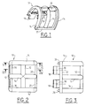
- Figures 1 to 5 represent schematically a first embodiment of the invention, in which a setting device form of a plastic conduit or pipe, in elastomer or rubber, consists of two half-cages identical 10 which can be assembled one to the other by snap or elastic snap and which, when they are placed around a duct, give the latter an elliptical shape in section transverse.
- Each half-cage 10 is molded of material rigid plastic, such as a fiber-filled polyamide glass, and includes three longitudinal bars 12 parallel and rectilinear interconnected by three bars parallel transverse 14 having the shape of a half ellipse.
- the transverse bars 14 are respectively at the ends and in the middle of the half-cage 10, and the longitudinal bars 12 connect the ends together transverse bars 14 and the middle parts of these bars, respectively.
- One of the longitudinal bars 12 connecting the ends of the transverse bars 14, comprises two hook tabs 16 which each extend between two transverse bars 14 and opposite the latter, tangentially to the half-ellipse defined by the half-cage 10 as can be seen in FIG. 4.
- Each tab 16 comprises a protruding beak 18 on its outer face, this spout 18 having a shape of arrowhead.
- the other longitudinal bar 12 connecting the ends of the transverse bars 14 of the half-cage 10 includes notches 20 on its inner face, these notches being intended to allow the passage of legs 16 and beaks 18 of another identical half-cage when assembling the device.
- the transverse bars 14 at the end of the cage 10 are formed with a projection 22 to oblique ramp at one end and with a notch 24 correspondingly shaped at their other end (figure 5).
- positioning pins 26 can be formed at the ends of one of the longitudinal bars 12 end ( Figure 3) to extend into the same direction as legs 16 while the other bar longitudinal end 12 includes orifices intended to receive the positioning pins 26 from another identical half-cage.
- the assembly of the device for implementing the invention is very simple: it suffices to have two identical half-cages 10 face to face as shown in FIG. 4, the legs 16 of a half-cage being aligned with the notches 20 of the other half-cage and vice versa, and to push the half -cages towards each other to automatically fix the half-cages to each other by hooking and elastic snap-fastening, the spouts 18 of the tabs 16 sliding on the edges of the notches 20 until snap-fastening elastic on the bars 12.
- the half-cages are made of a material sufficiently rigid and mechanically resistant to keep their shape in case the pressure at the inside of the duct becomes significantly higher than the ambient pressure.
- the device is removable without difficulty: just push the legs 16 inward and pull the half cages 10 for separate them from each other.
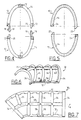
- Figures 6 and 7 differs from the one that has just been described in that it allows, not only to change the cross-sectional shape of the duct on which it is mounted, but also to modify the direction of this conduit, for example by bending it at 45 °.
- This device therefore includes, like the previous one, two identical or substantially identical half-cages 30, made of molded plastic and made of parallel longitudinal bars 32 connected between them by transverse bars 34 of semi-elliptical shape, the longitudinal bars 32 being rectilinear over part of their length and curved in an arc of circle in the vicinity of one of their ends, of such that a cross bar 34 located at one end of the half-cage is inclined by 45 °, for example, relative to the transverse bar 34 located at the other end of the half-cage.
- the longitudinal bars 32 are parallel to the longitudinal axis of symmetry a of the device, while the transverse bars 34 extend in planes perpendicular to this axis.
- a half-bar transverse 36 in quarter ellipse is provided between the two transverse bars 34 which connect the curved parts of the longitudinal bars 32, this half-bar transverse 36 extending between the longitudinal bar 32 located radially outermost by relative to the center of curvature of the curved ends bars 32, and the longitudinal bar 32 connecting the middle of cross bars 34.
- Figures 6 and 7 still differs from that of FIGS. 1 to 5 in that it comprises a half-cage of the male type comprising means elastic attachment or latching such as legs 16 of the previous embodiment, the other half-cage being of the female type and comprising the notches which will receive these means of hooking or snap-fastening elastic, the half-cage 30 shown in Figures 6 and 7 being of the female type.
- this half-cage 30 includes pins 38 protruding from one of the longitudinal bars 32, to receive for example a rubber pad which will serve as a support stop on a support.
- the faces of the bars 12, 14, 32, 34 which face the inside of the half-cages are substantially flat or slightly curved and tangential to the elliptical cross-sectional area defined by the half cages.
- the invention allows a setting simple, fast and reliable form of a conduit or pipe plastic or elastically deformable material, by means of a device which is mountable and dismountable without special tools.
- the half cages that come to be described can be replaced by half shells with solid walls or more or less openwork.
- the device according to the invention can be constituted by assembling and fixing more than two pieces, and it can be designed to change multiple times the form and eventually The direction of a conduit, for example for give an S or U shape to a part of the duct, if need is.
Description
L'invention concerne un conduit ou un tuyau en matière plastique ou en matière élastiquement déformable telle qu'un élastomère ou un caoutchouc, du type utilisable en particulier dans l'industrie automobile, associé à un dispositif de mise en forme.The invention relates to a conduit or pipe made of plastic or elastically deformable material such as an elastomer or a rubber, of the type usable in particular in the automotive industry, associated with a shaping device.
Les conduits ou tuyaux de diamètre relativement important qui sont montés dans les compartiments moteurs des véhicules automobiles, doivent souvent être munis de dispositifs de mise en forme permettant de modifier leur forme en section, notamment dans le sens de l'aplatissement, et/ou leur direction, par exemple pour contourner un obstacle, la nécessité de ces dispositifs étant due pour l'essentiel au manque d'espace disponible dans un compartiment moteur, ce qui oblige à couder et à aplatir certaines parties des conduits ou des tuyaux pour parvenir à les loger aux endroits voulus.Ducts or pipes of relatively diameter important which are mounted in the engine compartments motor vehicles, often require formatting devices to modify their shape in section, in particular in the sense of the flattening, and / or their direction, for example for work around an obstacle, the need for these devices being mainly due to the lack of available space in an engine compartment, which requires bending and flatten certain parts of the conduits or pipes to manage to house them in the desired places.
Dans la technique actuelle, ces dispositifs de mise en forme sont surmoulés en matière plastique rigide sur les conduits ou tuyaux, ce qui pose des problèmes qui peuvent être complexes. En effet, des noyaux solides doivent être disposés à l'intérieur des conduits pour le surmculage des dispositifs précités et peuvent être très difficiles à retirer après le surmoulage.In the current technique, these form are overmolded in rigid plastic on conduits or pipes, which poses problems which can be complex. Indeed, solid nuclei must be arranged inside the ducts for the overmoulding of the aforementioned devices and can be very difficult to remove after overmolding.
On connaít, par les documents GB-A-2 149 000 et FR-E-91 686, des dispositifs de fixation ou de serrage de câbles ou de conduits qui sont destinés à la fixation des câbles ou des conduits sur des supports, mais qui ne permettent pas de modifier leurs sections transversales.We know from GB-A-2 149 000 and FR-E-91 686, fixing or clamping devices cables or conduits which are intended for fixing cables or conduits on supports, but which do not not allow to modify their cross sections.
L'invention a pour but d'apporter une solution simple, efficace et peu coûteuse à ces problèmes.The invention aims to provide a solution simple, effective and inexpensive to these problems.
Elle a pour objet un dispositif de mise en forme d'un conduit ou d'un tuyau, qui puisse être monté à n'importe quel moment sur n'importe quelle partie du conduit ou du tuyau pour modifier sa forme en section transversale et éventuellement sa direction, qui soit également démontable et qui ne nécessite pas l'utilisation d'outils particuliers pour son montage ou son démontage.Its purpose is a device for form of a conduit or pipe, which can be mounted at any time on any part of the conduit or pipe to change its shape in section transverse and possibly its direction, which is also removable and which does not require the use of special tools for its assembly or disassembly.
Elle propose donc un conduit en matière plastique ou en matière élastiquement déformable, ce conduit ayant en section transversale une certaine forme initiale et étant associé à un dispositif de mise en forme comprenant au moins deux pièces rigides munies de moyens de fixation l'une sur l'autre et destinées à être assemblées autour du conduit en définissant entre elles un logement de réception de ce conduit, ce logement ayant une forme en section transversale différente de la forme initiale en section transversale du conduit et correspondant à une forme désirée de la partie transversale du conduit, de sorte que, quand les pièces sont fixées l'une à l'autre autour du conduit, elles le déforment et lui donnent en section transversale la forme désirée précitée.It therefore offers a conduit for plastic or elastically deformable material, this duct having a certain cross-section initial and being associated with a setting device form comprising at least two rigid parts provided with fastening means one on the other and intended to be assembled around the duct by defining between them a housing for receiving this conduit, this housing having a shape in cross section different from the shape initial cross section of the duct and corresponding to a desired shape of the part cross section of the duct, so that when the pieces are fixed to each other around the duct, they deform and give it in cross section the shape desired above.
Avantageusement, les moyens de fixation des pièces l'une sur l'autre sont des moyens d'accrochage ou d'encliquetage élastique.Advantageously, the means for fixing the pieces one on top of the other are hooking means or elastic snap.
Il suffit donc de mettre en place les pièces de part et d'autre du conduit, à l'endroit voulu, et de les fixer l'une à l'autre, notamment par accrochage ou encliquetage élastique, pour mettre en forme la partie correspondante du conduit, c'est-à-dire pour modifier sa forme en section transversale et éventuellement sa direction.So just put the pieces in place on either side of the conduit, at the desired location, and attach them to each other, in particular by hanging or elastic snap, to shape the part corresponding to the duct, i.e. to modify its shape in cross section and possibly its direction.
On évite ainsi tous les problèmes liés au surmoulage d'un manchon en matière rigide sur un conduit plus ou moins déformable.This avoids all the problems associated with overmolding a sleeve of rigid material on a conduit more or less deformable.
Dans un mode de réalisation préféré de l'invention, les pièces précitées sont des demi-cages constituées de barreaux reliés rigidement entre eux.In a preferred embodiment of the invention, the aforementioned parts are half-cages formed bars rigidly connected together.
Chaque pièce ou demi-cage est de préférence moulée d'une seule pièce en une matière plastique relativement rigide, par exemple en polyamide chargé de fibres de verre.Each piece or half-cage is preferably molded in one piece from relatively soft plastic rigid, for example of polyamide filled with fibers of glass.
Enfin, il peut être utile de prévoir sur ces pièces ou demi-cages des moyens de fixation ou de réception d'accessoires tels que des butées d'appui sur un support ou des organes de fixation sur support.Finally, it may be useful to plan on these parts or half-cages of the fixing or receiving means accessories such as support stops on a support or fasteners on support.
L'invention sera mieux comprise et d'autres
caractéristiques, détails et avantages de celle-ci
apparaítront plus clairement à la lecture de la
description qui suit, faite à titre d'exemple en
référence aux dessins annexés dans lesquels :
On se réfère d'abord aux figures 1 à 5 qui représentent schématiquement un premier mode de réalisation de l'invention, dans lequel un dispositif de mise en forme d'un conduit ou d'un tuyau en matière plastique, en élastomère ou en caoutchouc, est constitué de deux demi-cages identiques 10 qui peuvent être assemblées l'une à l'autre par accrochage ou encliquetage élastique et qui, lorsqu'elles sont mises en place autour d'un conduit, donnent à ce dernier une forme elliptique en section transversale.We first refer to Figures 1 to 5 which represent schematically a first embodiment of the invention, in which a setting device form of a plastic conduit or pipe, in elastomer or rubber, consists of two half-cages identical 10 which can be assembled one to the other by snap or elastic snap and which, when they are placed around a duct, give the latter an elliptical shape in section transverse.
Chaque demi-cage 10 est moulée en matière
plastique rigide, telle qu'un polyamide chargé de fibres
de verre, et comprend trois barreaux longitudinaux 12
parallèles et rectilignes reliés entre eux par trois barreaux
transversaux parallèles 14 ayant la forme d'une
demi-ellipse. Les barreaux transversaux 14 sont respectivement
aux extrémités et au milieu de la demi-cage 10, et
les barreaux longitudinaux 12 relient entre elles les extrémités
des barreaux transversaux 14 et les parties médianes
de ces barreaux, respectivement.Each half-
L'un des barreaux longitudinaux 12 reliant les
extrémités des barreaux transversaux 14, comprend deux
pattes 16 formant crochet qui s'étendent chacune entre
deux barreaux transversaux 14 et à l'opposé de ces derniers,
tangentiellement à la demi-ellipse définie par la
demi-cage 10 comme on le voit bien en figure 4.One of the
Chaque patte 16 comprend un bec 18 en saillie
sur sa face extérieure, ce bec 18 ayant une forme de
demi-pointe de flèche.Each
L'autre barreau longitudinal 12 reliant les
extrémités des barreaux transversaux 14 de la demi-cage
10 comprend des encoches 20 sur sa face intérieure, ces
encoches étant destinées à permettre le passage des
pattes 16 et des becs 18 d'une autre demi-cage identique
lors de l'assemblage du dispositif.The other
Les barreaux transversaux 14 d'extrémité de la
cage 10 sont quant à eux formés avec une saillie 22 à
rampe oblique à l'une de leurs extrémités et avec une encoche
24 de forme correspondante à leur autre extrémité
(figure 5). Enfin, des pions 26 de positionnement peuvent
être formés aux extrémités de l'un des barreaux longitudinaux
12 d'extrémité (figure 3) pour s'étendre dans le
même sens que les pattes 16 tandis que l'autre barreau
longitudinal 12 d'extrémité comprend des orifices destinés
à recevoir les pions de positionnement 26 d'une autre
demi-cage identique.The
L'assemblage du dispositif pour la mise en oeuvre de l'invention
est des plus simples :
il suffit de disposer deux demi-cages 10 identiques
face à face comme représenté en figure 4, les
pattes 16 d'une demi-cage se trouvant alignées avec les
encoches 20 de l'autre demi-cage et réciproquement, et de
pousser les demi-cages l'une vers l'autre pour réaliser
automatiquement la fixation des demi-cages l'une sur
l'autre par accrochage et encliquetage élastique, les
becs 18 des pattes 16 glissant sur les bords des encoches
20 jusqu'à l'encliquetage élastique sur les barreaux 12.The assembly of the device for implementing the invention is very simple:
it suffices to have two identical half-
Un conduit à section transversale circulaire
qui se trouve entre les demi-cages 10 prend alors la
forme elliptique définie par ces demi-cages assemblées
l'une à l'autre. Les demi-cages sont réalisées en une matière
suffisamment rigide et résistante mécaniquement
pour conserver leur forme dans le cas où la pression à
l'intérieur du conduit devient nettement supérieure à la
pression ambiante.A circular cross-section duct
which is between the half-
Le dispositif est démontable
sans difficulté : il suffit de repousser les pattes 16
vers l'intérieur et de tirer sur les demi-cages 10 pour
les écarter l'une de l'autre.The device is removable
without difficulty: just push the
Le dispositif des figures 6 et 7 diffère de celui qui vient d'être décrit en ce qu'il permet, non seulement de modifier la forme en section transversale du conduit sur lequel il est monté, mais également de modifier la direction de ce conduit, par exemple en le coudant à 45°.The arrangement of Figures 6 and 7 differs from the one that has just been described in that it allows, not only to change the cross-sectional shape of the duct on which it is mounted, but also to modify the direction of this conduit, for example by bending it at 45 °.
Ce dispositif comprend donc, comme le précédent,
deux demi-cages 30 identiques ou sensiblement identiques,
réalisées en matière plastique moulée et constituées
de barreaux longitudinaux 32 parallèles reliés
entre eux par des barreaux transversaux 34 de forme semi-elliptique,
les barreaux longitudinaux 32 étant rectilignes
sur une partie de leur longueur et incurvés en arc
de cercle au voisinage d'une de leurs extrémités, de
telle sorte qu'un barreau transversal 34 situé à une extrémité
de la demi-cage est incliné de 45°, par exemple,
par rapport au barreau transversal 34 situé à l'autre extrémité
de la demi-cage.This device therefore includes, like the previous one,
two identical or substantially identical half-
Les barreaux longitudinaux 32 sont parallèles
à l'axe longitudinal de symétrie a du dispositif, tandis
que les barreaux transversaux 34 s'étendent dans des
plans perpendiculaires à cet axe.The
Pour renforcer la demi-cage, un demi-barreau
transversal 36 en quart d'ellipse est prévu entre les
deux barreaux transversaux 34 qui relient entre elles les
parties incurvées des barreaux longitudinaux 32, ce demi-barreau
transversal 36 s'étendant entre le barreau longitudinal
32 situé radialement le plus à l'extérieur par
rapport au centre de courbure des extrémités incurvées
des barreaux 32, et le barreau longitudinal 32 reliant le
milieu des barreaux transversaux 34.To reinforce the half-cage, a half-bar
transverse 36 in quarter ellipse is provided between the
two
La variante de réalisation des figures 6 et 7
diffère encore de celle des figures 1 à 5 en ce qu'elle
comprend une demi-cage du type mâle comprenant des moyens
d'accrochage ou d'encliquetage élastique tels que les
pattes 16 du mode de réalisation précédent, l'autre demi-cage
étant du type femelle et comportant les encoches qui
vont recevoir ces moyens d'accrochage ou d'encliquetage
élastique, la demi-cage 30 représentée aux figures 6 et 7
étant du type femelle.The alternative embodiment of Figures 6 and 7
still differs from that of FIGS. 1 to 5 in that it
comprises a half-cage of the male type comprising means
elastic attachment or latching such as
En outre, cette demi-cage 30 comprend des
pions 38 formés en saillie sur l'un des barreaux longitudinaux
32, pour recevoir par exemple un patin en caoutchouc
qui servira de butée d'appui sur un support.In addition, this half-
On peut bien entendu prévoir sur les demi-cages
10 ou 30 d'autres moyens appropriés de fixation ou
d'accrochage d'organes de butée ou de fixation sur des
supports.We can of course provide on the half-
Dans les deux modes de réalisation qui viennent
d'être décrits, les faces des barreaux 12, 14, 32,
34 qui sont tournées vers l'intérieur des demi-cages sont
sensiblement planes ou légèrement incurvées et tangentielles
à la surface de section elliptique définie par
les demi-cages.In the two embodiments which come
to be described, the faces of the
Le nombre de barreaux, leurs dimensions, leur matière dépendent des contraintes que les dispositifs selon l'invention devront supporter. Il en va de même pour le nombre et les dimensions des moyens d'accrochage ou d'encliquetage élastique.The number of bars, their dimensions, their matter depend on the constraints that the devices according the invention will have to endure. It's the same for the number and dimensions of the attachment means or elastic snap.
De façon générale, l'invention permet une mise en forme simple, rapide et fiable d'un conduit ou tuyau en matière plastique ou en matière élastiquement déformable, au moyen d'un dispositif qui est montable et démontable sans outils particuliers.In general, the invention allows a setting simple, fast and reliable form of a conduit or pipe plastic or elastically deformable material, by means of a device which is mountable and dismountable without special tools.
Bien entendu, les demi-cages qui viennent d'être décrites peuvent être remplacées par des demi-coquilles à parois pleines ou plus ou moins ajourées. De même, le dispositif selon l'invention peut être constitué par l'assemblage et la fixation de plus de deux pièces, et il peut être conçu pour modifier plusieurs fois la forme et éventuellement la direction d'un conduit, par exemple pour donner une forme en S ou en U à une partie de conduit, si besoin est.Of course, the half cages that come to be described can be replaced by half shells with solid walls or more or less openwork. Of even, the device according to the invention can be constituted by assembling and fixing more than two pieces, and it can be designed to change multiple times the form and eventually The direction of a conduit, for example for give an S or U shape to a part of the duct, if need is.
Claims (9)
- Conduit made of a plastics or elastically deformable material, this conduit having a certain initial cross-sectional shape and being associated with a shaping device comprising at least two rigid pieces (10, 30) equipped with means (16, 18, 20) for fixing one piece to the other and intended to be assembled around the conduit defining between them a housing for receiving this conduit, this housing having a cross-sectional shape different from the initial cross-sectional shape of the conduit and corresponding to a desired shape of the transverse part of the conduit, so that, when the pieces (10, 30) are fixed to one another around the conduit, they deform it and give it the aforementioned desired cross-sectional shape.
- Conduit according to Claim 1, characterized in that the means for fixing the pieces (10, 30) are catch or snap-in means (16, 18, 20).
- Conduit according to Claim 1 or 2, characterized in that the aforementioned pieces are half-cages (10, 30) consisting of rigidly interconnected bars (12, 14, 32, 34).
- Conduit according to one of the preceding claims, characterized in that each aforementioned piece or half-cage is moulded in a single piece of rigid plastics material.
- Conduit according to Claim 4, characterized in that the said plastics material is a glass-fibre-reinforced polyamide.
- Conduit according to one of the preceding claims, characterized in that the aforementioned pieces or half-cages (10, 30) comprise means (38) for fixing or receiving accessories such as abutments for bearing on a support or members for fixing to a support.
- Conduit according to one of the preceding claims, characterized in that the shaping device is of elliptical section.
- Conduit according to one of the preceding claims, characterized in that the shaping device has a generally curved shape corresponding to at least one change of direction of the conduit.
- Conduit according to one of the preceding claims, characterized in that the aforementioned pieces or half-cages (10, 30) are formed of longitudinal bars (12) parallel to the longitudinal axis of the device and of curved transverse bars (14, 34) substantially perpendicular to this axis.
Applications Claiming Priority (2)
| Application Number | Priority Date | Filing Date | Title |
|---|---|---|---|
| FR9413190A FR2726625B1 (en) | 1994-11-04 | 1994-11-04 | DEVICE FOR SHAPING A CONDUIT OF PLASTIC MATERIAL OR ELASTICALLY DEFORMABLE MATERIAL |
| FR9413190 | 1994-11-04 |
Publications (2)
| Publication Number | Publication Date |
|---|---|
| EP0710792A1 EP0710792A1 (en) | 1996-05-08 |
| EP0710792B1 true EP0710792B1 (en) | 1999-03-31 |
Family
ID=9468499
Family Applications (1)
| Application Number | Title | Priority Date | Filing Date |
|---|---|---|---|
| EP95402382A Expired - Lifetime EP0710792B1 (en) | 1994-11-04 | 1995-10-25 | Device for preforming a pipe made of plastics or of elastically deformable material |
Country Status (5)
| Country | Link |
|---|---|
| US (1) | US5989006A (en) |
| EP (1) | EP0710792B1 (en) |
| DE (1) | DE69508701T2 (en) |
| ES (1) | ES2132564T3 (en) |
| FR (1) | FR2726625B1 (en) |
Families Citing this family (12)
| Publication number | Priority date | Publication date | Assignee | Title |
|---|---|---|---|---|
| US6354937B1 (en) * | 2000-02-05 | 2002-03-12 | Dale J. Crook | Flexible duct sleeve |
| DE202006008578U1 (en) * | 2006-05-30 | 2007-10-11 | Veritas Ag | Stabilizing element for a corrugated hose |
| US7914047B2 (en) * | 2007-09-20 | 2011-03-29 | Crook Dale J | Support for flexible duct bend |
| US8038175B2 (en) * | 2007-09-20 | 2011-10-18 | Crook Dale J | HVAC duct assembly and support |
| DE102009005643B4 (en) * | 2009-01-22 | 2017-03-30 | Siemens Healthcare Gmbh | Device for increasing the bending stiffness of hoses |
| US8844578B2 (en) | 2010-11-19 | 2014-09-30 | Rite-Hite Holding Corporation | Pliable-wall air ducts with internal expanding structures |
| US9200815B2 (en) * | 2012-08-24 | 2015-12-01 | Abc Industries, Inc. | Ventilation ducting arrangement |
| CZ304607B6 (en) * | 2013-05-07 | 2014-07-30 | Příhoda S.R.O. | Reinforcing system for air pipe line and air pipe line per se |
| US9080715B2 (en) | 2013-10-02 | 2015-07-14 | Steelcase Inc. | Support device for suspending an article from a horizontal object |
| US9644858B2 (en) | 2014-05-29 | 2017-05-09 | Rite-Hite Holding Corporation | Externally tensioned pliable air ducts |
| USD907957S1 (en) | 2018-10-12 | 2021-01-19 | Rich Products Corporation | Dispensing fitment |
| USD941088S1 (en) | 2019-03-26 | 2022-01-18 | Rich Products Corporation | Dispensing fitment |
Family Cites Families (14)
| Publication number | Priority date | Publication date | Assignee | Title |
|---|---|---|---|---|
| FR1341140A (en) * | 1962-12-10 | 1963-10-25 | Plastic clamp formed from two elements for the individual laying of electric cables or tubular conduits of different diameters | |
| GB1009534A (en) * | 1963-10-09 | 1965-11-10 | Pumpire Ltd | Hose protecting device |
| FR91686E (en) * | 1966-03-12 | 1968-07-26 | Metal Usine Soc Ind Du | Hose clamp for tubes or similar objects |
| US3471110A (en) * | 1966-09-22 | 1969-10-07 | Superior Continental Corp | Cable clamp |
| FR92686E (en) * | 1967-07-18 | 1968-12-13 | Stops control device on floors of elevators, freight elevators and similar devices | |
| FR1559036A (en) * | 1968-01-04 | 1969-03-07 | ||
| US3765629A (en) * | 1971-04-16 | 1973-10-16 | Standard Oil Co | Conduit support and spacer means |
| US3843083A (en) * | 1972-11-09 | 1974-10-22 | Wonder Piles | Mounting apparatus for portable device |
| US4258515A (en) * | 1977-09-13 | 1981-03-31 | Owen William J | Conduit trunking |
| US4669757A (en) * | 1982-08-05 | 1987-06-02 | Bartholomew Donald D | High pressure fluid conduit assembly |
| GB8327578D0 (en) * | 1983-10-14 | 1983-11-16 | Phillips Petroleum Co | Saddle clamp for tubular drill strings |
| DE3671091D1 (en) * | 1985-02-04 | 1990-06-13 | Witzenmann Metallschlauchfab | BENDABLE WAVE PIPE WITH PARALLELS, RING-SHAPED SHAFTS AND AXIAL SUPPORT. |
| US5088672A (en) * | 1991-01-02 | 1992-02-18 | Neuendorf Paul A | Circumscribing sign clamp and method of fabrication |
| US5435506A (en) * | 1994-03-02 | 1995-07-25 | United Technologies Corporation | Clamp with mechanically attached grommet |
-
1994
- 1994-11-04 FR FR9413190A patent/FR2726625B1/en not_active Expired - Lifetime
-
1995
- 1995-10-25 ES ES95402382T patent/ES2132564T3/en not_active Expired - Lifetime
- 1995-10-25 EP EP95402382A patent/EP0710792B1/en not_active Expired - Lifetime
- 1995-10-25 DE DE69508701T patent/DE69508701T2/en not_active Expired - Lifetime
-
1997
- 1997-06-30 US US08/884,608 patent/US5989006A/en not_active Expired - Fee Related
Also Published As
| Publication number | Publication date |
|---|---|
| US5989006A (en) | 1999-11-23 |
| FR2726625B1 (en) | 1996-12-13 |
| EP0710792A1 (en) | 1996-05-08 |
| ES2132564T3 (en) | 1999-08-16 |
| FR2726625A1 (en) | 1996-05-10 |
| DE69508701T2 (en) | 1999-11-04 |
| DE69508701D1 (en) | 1999-05-06 |
Similar Documents
| Publication | Publication Date | Title |
|---|---|---|
| EP1064489B1 (en) | Snap-on pipe fitting | |
| EP0710792B1 (en) | Device for preforming a pipe made of plastics or of elastically deformable material | |
| EP1703188B1 (en) | Fixing clamp | |
| EP1012483B1 (en) | Arrangement for fixing a tubular element on a structural element of a motor vehicle body | |
| EP2602531B1 (en) | Locking member of a connection device for fluid transfer, said device and method for locking same | |
| EP0583183B1 (en) | Coupling device for connecting tubes | |
| EP1921362B1 (en) | Double clamp collar and assembly method | |
| EP0327440A1 (en) | Connection between a heat exchanger and a tubular member | |
| FR2942650A1 (en) | FAST CONNECTION COUPLING DEVICE | |
| FR2901858A1 (en) | SUPPORT FOR WELL TUBE | |
| EP1056969B1 (en) | Snap-on connection for fluid conduit | |
| FR2703126A1 (en) | Conduit, in particular for a motor vehicle. | |
| EP0543721B1 (en) | Clutch release bearing with a metallic push-plate and method of making the same | |
| EP3640516A1 (en) | Quick coupling device | |
| EP1574740B1 (en) | Vibration damping connecting device | |
| FR2808870A1 (en) | Heat exchanger with air flow guide in motor vehicle, uses air guide plate clipped onto one end of radiator in hinge structure to allow plate to then be closed over radiator and held closed by clip fastenings | |
| EP1036966B1 (en) | Clip for fastening tubes or the like | |
| EP0603033B1 (en) | Quick-acting coupling for fluid conduits | |
| FR2652872A1 (en) | Connector for a pipe | |
| FR2623857A1 (en) | Fixing device for tubing or the like | |
| EP4206092A1 (en) | Means for fixing a wheel of a refuse collection container | |
| FR2754873A1 (en) | Motor vehicle cable guide sheath | |
| EP0392908A1 (en) | Joint for pipes | |
| FR2775507A1 (en) | Snap-on connector for fluid conduit especially in motor vehicle air conditioning circuits | |
| FR2710387A1 (en) | Improved valve assembly. |
Legal Events
| Date | Code | Title | Description |
|---|---|---|---|
| PUAI | Public reference made under article 153(3) epc to a published international application that has entered the european phase |
Free format text: ORIGINAL CODE: 0009012 |
|
| AK | Designated contracting states |
Kind code of ref document: A1 Designated state(s): DE ES GB IT |
|
| 17P | Request for examination filed |
Effective date: 19960619 |
|
| 17Q | First examination report despatched |
Effective date: 19970310 |
|
| GRAG | Despatch of communication of intention to grant |
Free format text: ORIGINAL CODE: EPIDOS AGRA |
|
| GRAG | Despatch of communication of intention to grant |
Free format text: ORIGINAL CODE: EPIDOS AGRA |
|
| GRAH | Despatch of communication of intention to grant a patent |
Free format text: ORIGINAL CODE: EPIDOS IGRA |
|
| GRAH | Despatch of communication of intention to grant a patent |
Free format text: ORIGINAL CODE: EPIDOS IGRA |
|
| GRAA | (expected) grant |
Free format text: ORIGINAL CODE: 0009210 |
|
| AK | Designated contracting states |
Kind code of ref document: B1 Designated state(s): DE ES GB IT |
|
| REF | Corresponds to: |
Ref document number: 69508701 Country of ref document: DE Date of ref document: 19990506 |
|
| GBT | Gb: translation of ep patent filed (gb section 77(6)(a)/1977) |
Effective date: 19990629 |
|
| REG | Reference to a national code |
Ref country code: ES Ref legal event code: FG2A Ref document number: 2132564 Country of ref document: ES Kind code of ref document: T3 |
|
| PLBE | No opposition filed within time limit |
Free format text: ORIGINAL CODE: 0009261 |
|
| STAA | Information on the status of an ep patent application or granted ep patent |
Free format text: STATUS: NO OPPOSITION FILED WITHIN TIME LIMIT |
|
| 26N | No opposition filed | ||
| REG | Reference to a national code |
Ref country code: GB Ref legal event code: IF02 |
|
| PGFP | Annual fee paid to national office [announced via postgrant information from national office to epo] |
Ref country code: GB Payment date: 20131021 Year of fee payment: 19 Ref country code: DE Payment date: 20131021 Year of fee payment: 19 |
|
| PGFP | Annual fee paid to national office [announced via postgrant information from national office to epo] |
Ref country code: IT Payment date: 20131028 Year of fee payment: 19 Ref country code: ES Payment date: 20131029 Year of fee payment: 19 |
|
| REG | Reference to a national code |
Ref country code: DE Ref legal event code: R119 Ref document number: 69508701 Country of ref document: DE |
|
| GBPC | Gb: european patent ceased through non-payment of renewal fee |
Effective date: 20141025 |
|
| PG25 | Lapsed in a contracting state [announced via postgrant information from national office to epo] |
Ref country code: DE Free format text: LAPSE BECAUSE OF NON-PAYMENT OF DUE FEES Effective date: 20150501 Ref country code: GB Free format text: LAPSE BECAUSE OF NON-PAYMENT OF DUE FEES Effective date: 20141025 |
|
| PG25 | Lapsed in a contracting state [announced via postgrant information from national office to epo] |
Ref country code: IT Free format text: LAPSE BECAUSE OF NON-PAYMENT OF DUE FEES Effective date: 20141025 |
|
| REG | Reference to a national code |
Ref country code: ES Ref legal event code: FD2A Effective date: 20151126 |
|
| PG25 | Lapsed in a contracting state [announced via postgrant information from national office to epo] |
Ref country code: ES Free format text: LAPSE BECAUSE OF NON-PAYMENT OF DUE FEES Effective date: 20141026 |