EP0710035A2 - Farbbildprojektor - Google Patents
Farbbildprojektor Download PDFInfo
- Publication number
- EP0710035A2 EP0710035A2 EP95307693A EP95307693A EP0710035A2 EP 0710035 A2 EP0710035 A2 EP 0710035A2 EP 95307693 A EP95307693 A EP 95307693A EP 95307693 A EP95307693 A EP 95307693A EP 0710035 A2 EP0710035 A2 EP 0710035A2
- Authority
- EP
- European Patent Office
- Prior art keywords
- light
- component
- image
- colour
- blue
- Prior art date
- Legal status (The legal status is an assumption and is not a legal conclusion. Google has not performed a legal analysis and makes no representation as to the accuracy of the status listed.)
- Granted
Links
- 230000004907 flux Effects 0.000 claims abstract description 77
- 239000004973 liquid crystal related substance Substances 0.000 claims abstract description 47
- 230000003287 optical effect Effects 0.000 claims abstract description 42
- 238000002834 transmittance Methods 0.000 claims description 16
- 230000005855 radiation Effects 0.000 claims description 5
- 239000010410 layer Substances 0.000 description 11
- 230000000694 effects Effects 0.000 description 5
- 239000000758 substrate Substances 0.000 description 4
- 239000003086 colorant Substances 0.000 description 3
- 239000005262 ferroelectric liquid crystals (FLCs) Substances 0.000 description 3
- 230000007704 transition Effects 0.000 description 3
- 238000004519 manufacturing process Methods 0.000 description 2
- 230000002194 synthesizing effect Effects 0.000 description 2
- 239000004988 Nematic liquid crystal Substances 0.000 description 1
- 239000011247 coating layer Substances 0.000 description 1
- 239000013078 crystal Substances 0.000 description 1
- 239000011521 glass Substances 0.000 description 1
- 239000007788 liquid Substances 0.000 description 1
- 239000004033 plastic Substances 0.000 description 1
- 229920003023 plastic Polymers 0.000 description 1
- 230000010287 polarization Effects 0.000 description 1
- 125000006850 spacer group Chemical group 0.000 description 1
Images


Classifications
-
- H—ELECTRICITY
- H04—ELECTRIC COMMUNICATION TECHNIQUE
- H04N—PICTORIAL COMMUNICATION, e.g. TELEVISION
- H04N9/00—Details of colour television systems
- H04N9/12—Picture reproducers
- H04N9/31—Projection devices for colour picture display, e.g. using electronic spatial light modulators [ESLM]
- H04N9/3102—Projection devices for colour picture display, e.g. using electronic spatial light modulators [ESLM] using two-dimensional electronic spatial light modulators
- H04N9/3105—Projection devices for colour picture display, e.g. using electronic spatial light modulators [ESLM] using two-dimensional electronic spatial light modulators for displaying all colours simultaneously, e.g. by using two or more electronic spatial light modulators
-
- G—PHYSICS
- G02—OPTICS
- G02B—OPTICAL ELEMENTS, SYSTEMS OR APPARATUS
- G02B27/00—Optical systems or apparatus not provided for by any of the groups G02B1/00 - G02B26/00, G02B30/00
- G02B27/28—Optical systems or apparatus not provided for by any of the groups G02B1/00 - G02B26/00, G02B30/00 for polarising
- G02B27/283—Optical systems or apparatus not provided for by any of the groups G02B1/00 - G02B26/00, G02B30/00 for polarising used for beam splitting or combining
Definitions
- the present invention relates to a colour image projecting apparatus.
- the basic structure of a conventional reflecting type liquid crystal image projecting apparatus is composed of a plurality of reflecting type optical writing liquid crystal light valves; writing means each for optically writing an image of each colour component to each of the reflecting type light writing liquid crystal light valves by illuminating a writing light from one face side thereof; a polarised light illuminating optical system for illuminating polarised light illuminating luminous fluxes corresponding to the respective colour components on reading faces of the respective reflecting type optical writing liquid crystal light valves and reflectively reading images of the respective colour components written in the reflecting type optical writing liquid crystal light valves; and a projecting optical system for synthesising, magnifying and projecting the read images of the respective colour components thereby projecting a colour image.
- Fig. 3 is a sectional view showing the structure of the reflecting type optical writing liquid crystal light valve.
- Transference electrode layers 302a and 302b and orientation film layers 303a and 303b are provided on the surfaces of transparent substrates 301a and 301b such as glass or plastics for sandwiching liquid crystal molecules.
- the transparent substrates 301a and 301b on their respective sides of the orientation film layers 303a and 303b are opposed while controlling the clearance by interposing spacers 309 thereby sandwiching a liquid crystal layer 304.
- a photoconductive layer 305, a light shielding layer 306 and a dielectric mirror 307 are laminated between the transference electrode layer 302a on the side of writing by light and the orientation film layer 303a and reflectionless coating layers 308a and 308b are formed on outer faces of cells of the transparent substrate 301a on the side of writing and the transparent substrate 301b on the side of reading.
- liquid crystals of the liquid crystal layer 304 nematic liquid crystals or ferroelectric liquid crystals etc. are used.
- a reflecting type liquid crystal light valve using ferroelectric liquid crystals is provided with a very fast operational speed of several hundreds Hz or more.
- the reflecting type light writing liquid crystal light valve using the ferroelectric liquid crystals is a device for thresholding and making binary an input image, it is also possible to perform a gray scale display by devising the waveform of a drive voltage.
- a polarized light component of a luminous flux is limited to a linearly polarized light, for example, a s polarized light component formed by a polarizing plate etc. that is irradiated on the reflecting type optical writing liquid crystal light valve.
- a linearly polarized light of a luminous flux reflected by the reflecting type optical writing liquid crystal light valve that is orthogonal to the polarization axis of the linearly polarized light of the incident luminous flux for example, (a p polarized light component)
- the image read in such a way becomes a positive image.
- This reflecting type liquid crystal image projecting apparatus is composed of three sheets of reflecting type optical writing liquid crystal light valves. That is, the apparatus includes a reflecting type optical writing liquid crystal light valve (hereinafter, R-SLM) 113 allocated with a red image among those having three elementary colors of red, green and blue, a reflecting optical writing liquid crystal light valve (hereinafter, G-SLM) 105 allocated with a green image and a reflecting type optical writing liquid crystal light valve (hereinafter, B-SLM) 110 allocated with a blue image.
- R-SLM reflecting type optical writing liquid crystal light valve
- G-SLM reflecting optical writing liquid crystal light valve
- B-SLM reflecting type optical writing liquid crystal light valve
- This reflecting type liquid crystal image projecting apparatus includes TFT liquid crystal panels and writing lenses as writing means of the respective images of the respective color components and a red component image displayed by the R-TFT 115 is optically written on a writing face of the R-SLM 113 by the R-writing lens 114. Similarly, a green component image displayed by the G-TFT 107 is optically written on a writing face of the G-SLM 105 by the G-writing lens 106. Further, a blue component image displayed by the B-TFT 112 is optically written on a writing face of the B-SLM 110 by the B-writing lens 111.
- the apparatus includes as a polarized light illuminating optical system a light source 101, an illuminating lens system 102, a polarized beam splitter (hereinafter, PBS) 103, a red reflecting dichroic mirror (hereinafter, R-DM) 402 and a blue reflecting dichroic mirror (hereinafter, B-DM) 401.
- a luminous flux emitted from the light source 101 becomes an illuminating luminous flux irradiated on the reflecting type optical writing liquid crystal light valves by the illuminating lens system 102.
- the illuminating light flux is split into mutually orthogonal polarized illuminating fluxes by the PBS 103.
- one polarized illuminating flux reflected by the PBS 103 is, for example, a s polarized light
- the other polarized illuminating luminous flux transmitted through the PBS 103 becomes a p polarized light.
- Only a red component included in the s polarized light component is selectively reflected by the R-DM 402 which is irradiated on the R-SLM 113 and reflectively reads a red component image.
- the remaining color component transmitted through the R-DM 113 is separated into a green component and a blue component by the B-DM 401.
- a green component transmitted through the B-DM 401 is irradiated on the G-SLM 105 and reflectively reads a green component image.
- the blue component reflected by the B-DM 401 is irradiated on the B-SLM 110 and reflectively reads a blue component image.
- the three kinds of the red component image, the green component image and the blue component image which have been read in this way, are again synthesized by the B-DM 401 and the R-DM 402, the synthesized transmits through the PBS 103 and is magnified and projected on a screen 117 in front via a projecting lens 116. As a result, a color image is projected on the surface of the screen 117.
- the light source luminous flux is separated into a s polarised light and a p polarised light component by using the PSB 103 and only the s polarised light (or p polarised light) component is taken out as a polarised light illuminating luminous flux.
- the other p polarised light (or s polarised light) component is not used at all as an illuminating luminous flux. Accordingly, in the conventional structure the utilisation efficiency of the light source luminous flux cannot exceed 50% and the brightness of the projected colour image is low.
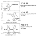
- Fig. 5(a) and Fig. 5(b) are views showing the reflectance characteristics of the B-DM 401 and the R-DM 402 with respect to the s polarised light component and the p polarised light component.
- These drawings illustrate the characteristics in case where the luminous flux is incident on the B-DM 401 and the R-DM 402 by an angle of 45°. It is very difficult and almost impossible to make the reflectance characteristics with respect to the s polarised light component and the p polarized light component agree with each other.
- the R-DM 402 is provided with the characteristic shown in Fig. 5(b) therefore, the polarized light illuminating luminous flux having the s polarized light component that is reflected by the PBS 103 for illuminating the R-SLM 113 is provided with the wavelength characteristic of the s polarized light shown in Fig. 5(b).
- the luminous flux that is modulated and reflected by the R-SLM 113 therefore, is reflected by the R-DM 402 and transmits through the PBS 103 thereby enabling to read the image of the red component.
- the red image of the red color component is composed of only the p polarized light component. That is, the luminous flux in compliance with the wavelength characteristic of the p polarized light is obtained by the R-DM 402. A difference of characteristics between the s polarized light and the p polarized light shown by a hatched portion of Fig. 5(b) is not utilized and becomes a total loss. Similarly, the same is applicable to the blue component reflected by the B-DM 401 and a difference between characteristics of the s polarized light and the p polarized light shown by a hatched portion of Fig. 5(a) becomes a total loss. With regard to the green component, only the s polarized light component which has not been reflected in Fig.
- At least two sheets of the color separating mirrors (that is the B-DM 401 and the R-DM 402) are necessary between the PBS 103 and the G-SLM 105 or the B-SLM 110. That is, the back focus of the projecting lens must be set long since the optical lengths from the projecting lens 116 to the G-SLM 105 and the B-SLM 110 become long. Accordingly, the F number of the projecting lens becomes large. Meanwhile, a bright and highly-magnified projecting lens is necessary to magnify and project a colour image having a high brightness. Accordingly, it is extremely difficult to design and manufacture a projecting lens which satisfies the mutually conflicting required characteristics.
- an image projection apparatus having a light source emitting radiation comprising high, medium and low frequency ranges and characterised by beam splitting means for splitting the radiation from the light source into first and second beams; means for receiving a first of said beams, and forming and image component in said medium frequency range; means for receiving a second of said beams and forming respective image components in said high and low frequency ranges; and means for forming an image from said image components.
- the high, medium and low frequency ranges correspond to blue, green and red, respectively.
- the means for receiving the first of the beams from the beam splitting means comprises a band pass filter which passes green light.
- the first beam provides the green image components of the final image.
- the means for receiving the second of the beams (which provides the red and blue components of the final image) includes a dichroic mirror.
- the beam splitting means comprises a polarising beam splitter which provides light having a predetermined polarisation direction to the dichroic mirror.
- the dichroic mirror has different reflectance and transmittance characteristics depending on the polarisation direction of the light applied thereto. The light having a frequency below a predetermined frequency is transmitted through the dichroic mirror and is incident on a first liquid crystal light valve.
- the light which has a frequency which is above the predetermined frequency is reflected from the dichroic layer and is incident on a second liquid crystal light valve.
- the liquid crystal light valves impart respective image components to the light components incident thereon, and reverse the polarisation direction thereof.
- the light components are reflected back to the dichroic mirror.
- the frequency at which the dichroic mirror undergoes the transition from being a reflector to a transmitter of light is different.
- some of the light is not returned to the polarising beam splitter, and thus does not contribute to the final image.
- the embodiment of the present invention prevents or reduces the loss of brightness of the final image.
- a band stop filter which admits only blue and red light may be provided to remove any remaining component of the green light before the second of the light beams is returned to the polarising beam splitter.
- the frequency at which the dichroic layer undergoes the transition from being a reflector to being a transmitter of light is set so that it corresponds to a frequency between that of blue light and that of green light for light having a first polarisation direction, and the frequency at which the dichroic mirror undergoes a transition from being a reflector to being a transmitter is set between the frequency of red light and green light for light which is polarised in the opposite direction, then the band stop filter may be omitted. This is because the dichroic mirror, by virtue of its different reflectance/transmittance characteristics to oppositly polarised light, removes the green component of the light.
- the arrangement of the present embodiment utilises both the first and second light beams generated by the polarising beam splitter.
- the prior art arrangement described above utilises only one of the beams from the polarising beam splitter, thus reducing the efficiency of the image projection apparatus.
- the present invention provides a reflecting type colour image projecting apparatus including three sheets of reflecting type optical writing liquid crystal light valves, writing means each for writing an image of each colour component allocated to each reflection type optical writing liquid crystal light valve by illuminating a writing light from a writing face of each reflecting type optical writing liquid crystal light valve, a light emitting source and an illuminating lens for illuminating a light source luminous flux, a polarised beam splitter for splitting the light source luminous flux into polarised light illuminating fluxes, a green colour separating means for separating only a green component of one of the polarised light illuminating luminous fluxes, a red and blue colour separating means for separating the other one of the polarised light illuminating luminous fluxes into a red component and a blue component and a projecting lens for magnifying and projecting a read colour image.
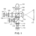
- Fig. 1 shows the structure of a first embodiment of a reflecting type colour image projecting apparatus according to the present invention.
- Figs. 2A-D show the waveform characteristics of respective colour components according to the first embodiment of the present invention.
- Fig. 3 is a sectional view showing a structure of a reflecting type optical writing liquid crystal light valve.
- Fig. 4 shows the structure of a conventional reflecting type colour image projecting apparatus.
- Figs. 5A-C show the waveform characteristics of respective colour components in the conventional example.
- Fig. 6 shows the structure of a second embodiment of a reflecting type colour image projecting apparatus according to the present invention.
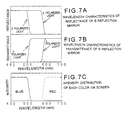
- Figs. 7A-C show the waveform characteristics of the respective colour components according to the second embodiment.
- Fig. 8 shows the structure of a third embodiment of the reflecting type colour image projecting apparatus according to the present invention.
- the images corresponding to the respective colour components are written to the three sheets of the reflecting type optical writing liquid crystal light valves by TFT panels or the like.
- the polarised light illuminating fluxes are produced by splitting the light source luminous flux emitted from the light emitting source by the polarised beam splitter. Thereafter, with regard to the one of the polarised light illuminating luminous fluxes (for example, the s polarised light component), only the green component thereof is illuminated on the green reflecting type optical reading liquid crystal light valve as a reading light by the green colour separating means such as a band pass filter etc. transmitting only the green component.
- the green component is stop by the red and the blue colour separating means which separates the red component and the blue component and only the red and the blue components are respectively illuminated on the red and the blue reflection type optical writing liquid crystal light valves as reading lights.
- the images of the respective color components written in the respective reflecting type optical writing liquid crystal light valves are read and an image having the red, green and blue components is synthesized by the red and the blue color separating means and the polarized beam splitter. Thereafter, the synthesized color image is magnified and projected on the screen by the projecting lens.
- the back focus from the projecting lens to the reflecting type optical writing liquid crystal light valves can be shortened and further, the utilization efficiency of the luminous flux of the light emitting source can more be enhanced than that of the conventional reflection type color image projecting apparatus.
- Fig. 1 is a structural view of a first embodiment of a reflecting type color image projecting apparatus of the present invention.
- the first embodiment of the present invention is a polarized light separating and synthesizing optical system which is constituted by a PBS 103, a green band pass filter (hereinafter, GBF) 104 transmitting only a green component of a polarized light illuminating luminous flux of a s polarized light component reflected by the PBS 103, a green cut filter (hereinafter, GCF) 108 separating red and blue components by cutting a green component from a polarized light illuminating luminous flux of a p polarized light component which has transmitted through the PBS 103 and a blue reflecting mirror 109.
- GBF green band pass filter
- GCF green cut filter
- Writing means each is constituted by a TFT panel and a writing lens for each color component.
- the writing means with respect to the green component is constituted by a G-TFT 107 displaying an image of the green component and a G-writing lens 106 for writing the displayed image to a G-SLM 105.
- the image of the green component displayed on the G-TFT 107 is read by illuminating a reading light from behind the G-TFT 107.
- the read image is written to the G-SLM 105 by the G-writing lens 106.
- the writing means with respect to the blue component is constituted by a B-TFT 112 and a B-writing lens 111.
- the writing means with respect to the red component is constituted by a R-TFT 115 and a R-writing lens 114.
- the TFT panels are used for the writing means of the images in this embodiment, a device or an optical system capable of displaying two-dimensional images such as a CRT or a laser scanning optical system etc. may naturally be used.
- the GBF 104 is used as a green color separating means separating only the green component of the polarized light illuminating luminous flux of the s polarized light component.
- the green color separating means an optical part etc. capable of separating only the green component such a green reflection mirror etc. may naturally used.
- a luminous flux emitted from a light emitting source 101 is illuminated on the PBS 103 as a light source luminous flux by an illuminating lens 102.
- the light source luminous flux illuminated on the PBS 103 becomes a polarized light illuminating luminous flux which is a luminous flux of only a p polarized light or a s polarized light component by transmitting through or being reflected by the PBS 103.
- the polarized light illuminating luminous flux of a s polarized light component reflected by the PBS 103 transmits through the GBF 104 having the wavelength characteristic as shown in Fig. 2(c).
- the polarized light illuminating luminous flux which has transmitted through the GBF 104 is irradiated on the G-SLM 106 as a reading light. Further, the reading light reflected by the G-SLM 105 again transmits through the GBF 104 and transmits through the PBS 103.
- the wavelength characteristic of the green component of the image which is magnified and projected by a projecting lens 116 is shown in Fig. 2(d) by a dotted line.
- the polarized light illuminating luminous flux is incident approximately orthogonally on the GBF 104 and therefore, there is no difference between the wavelength characteristics of the transmittances (reflectances) of the s polarized light and the p polarized light.
- the green component of the polarized light illuminating luminous flux of the p polarized component which has transmitted through the PBS 103 is cut by transmitting through the GCF 108.
- the wavelength characteristic of the transmittance of the GCF 108 is shown in Fig. 2(b).
- the polarized light illuminating luminous flux which has transmitted through the GCF 108 in such a way is separated into the blue component and the red component by the B-reflecting mirror 109.
- the reflectance characteristic of the B-reflecting mirror 109 is shown in Fig. 2(a).
- a portion (hatched portion) of the figure showing a difference between the wavelength characteristics of the p polarized light component and the s polarized light component is in a band wherein these components cannot be transmitted through the GCF 108 and therefore, the blue component and the red component are determined by the transmittance characteristic of the GCF 108.
- the blue component of the polarized light illuminating luminous flux reflected by the B-reflecting mirror 109 is incident on the B-SLM 110 as a reading light.
- the incident reading light is reflected by the B-SLM 110.
- the red component of the polarized light illuminating luminous flux which has transmitted through the B-reflecting mirror 109 is similarly illuminated on the R-SLM 113 as a reading light and is reflected thereby.
- the reading lights reflected by the B-SLM 110 and the R-SLM 113 are synthesized by the blue reflecting mirror and again transmit through the GCF 108.
- the red and blue components which have transmitted through the GCF 108 are reflected by the PBS 103 and are synthesized with the image of the green component by the PBS 103.
- the bands of the blue component and the red component are determined by the band of the GCF 108 and the components are separated in two colors by the B-reflecting mirror 109.
- Fig. 2(d) The wavelength characteristics of the images of the red component and the blue component are shown by Fig. 2(d) in a bold line. Further, a color image synthesized by the three colors of red, green and blue is magnified and projected on a screen 117 by a projecting lens 116.
- the wavelength band of the green component can be determined only by the GBF 104.
- the utilization efficiency of the light source luminous flux can be enhanced by pertinently utilizing the wavelength band of the green color.
- the band of the blue component becomes a product of the transmittance characteristic of the GCF 108 by the reflectance characteristics of the p polarized light component of the B-reflecting mirror 109.
- the band of the red component becomes a product of the transmittance characteristic of the GCF 108 by the transmittance characteristic of the s polarized light component of the B-reflecting mirror 109.
- Fig. 6 is a structural view of a second embodiment of a reflecting type color image projecting apparatus according to the present invention.
- This embodiment is an embodiment in which the GCF 108 is omitted in the first embodiment of Fig. 1.
- Feature is provided to the wavelength characteristic of a B-reflecting mirror 601 as a substitute for the omitted GCF 108. Therefore, the explanation of this embodiment is partially omitted or simplified with respect to the portions the same as the structure of the first embodiment.
- the polarized light illuminating luminous flux is separated into the blue component and the red component by the GCF 108 and the B-reflecting mirror 109.
- the B-reflecting mirror 601 having the wavelength characteristics shown in Fig. 7(a) and Fig. 7(b) is used.
- the B-reflecting mirror 601 is used in 45 ° incidence and therefore, there causes a difference between the wavelength characteristics of the s polarized light component and the p polarized light component of the reflected or transmitted light as shown in Fig. 7(a).
- the difference between the s polarized light component and the p polarized light component is controlled in manufacturing the B-reflecting mirror 601.
- the green component of the polarized light illuminating luminous flux of the p polarized light component is cut by using a pertinent difference between the wavelength characteristics of the s polarized light component and the p polarized light component.
- the polarized light illuminating luminous flux having only the p polarized light component which has transmitted through the PBS 103 is reflected by the B-reflecting mirror 601 and is illuminated on the B-SLM 110 as a reading light. Thereafter, the reading light which has been reflected by the B-SLM 110 is modulated in accordance with the written image of the blue component and is again reflected by the B-reflecting mirror 601. Thereafter, only the s polarized light component is reflected by the PBS 103 and is magnified and projected on the screen 117 by the projecting lens 116.
- the wavelength characteristic of the image of the blue component which has been projected on the screen 117 is shown by Fig. 7(c) in a bold line.
- the polarized light illuminating luminous flux of the image of the blue component is composed of only the p polarized light component and therefore, it conforms to the wavelength band of the p polarized light component having a shorter wavelength in the reflectance wavelength characteristic of the B-reflecting mirror 601 shown in Fig. 7(a).
- the polarized light illuminating luminous flux which has transmitted through the blue reflecting mirror is illuminated on the R-SLM 113 as a reading light.
- the wavelength band of the reading light illuminated on the R-SLM 113 becomes a wavelength band of the p polarized light component having the transmittance characteristic of the B-reflecting mirror 601 as shown in Fig. 7(b).
- the reading light reflected by the R-SLM 113 is modulated in correspondence with the written image of the red component and again transmits through the B-reflecting mirror 601.
- only the s polarized light component is reflected by the PBS 103 and is magnified and projected on the screen 117 by the projecting lens 116.
- the wavelength characteristic of the image of the red component projected on the screen 117 is shown by Fig. 7(c) in a dotted line. That is, although the polarized light illuminating luminous flux of the image of the red component is composed of only the p polarized light component, since only the s polarized light component luminous flux is reflected by the PBS 103, it conforms to the wavelength band of the s polarized light component having a longer wavelength in the transmittance wavelength characteristic of the B-reflecting mirror 601 as shown in Fig. 7(b).
- the green component of the polarized light illuminating luminous flux having only the p polarized light component which has transmitted through the PBS 103 is cut and the flux is separated into the red and blue components and only the green component of the polarized light illuminating luminous flux of the s polarized light component which has passed through PBS 103 can be taken out. Thereafter, the red, green and blue components are synthesized by the PBS 103 and the B-reflecting mirror 601 and a color image can be magnified and projected on the screen 117 by the projecting lens 116.
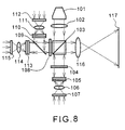
- Fig. 8 is a structural view of a third embodiment of a reflecting type color image projecting apparatus according to the present invention.
- This embodiment is an embodiment in which in the first embodiment of Fig. 1 the green component uses the polarized light illuminating luminous flux of the p polarized light component which has transmitted through the PBS 103 and the red and blue components use the polarized light illuminating luminous flux of the s polarized light component which has been reflected by the PBS 103. Accordingly, the explanation of the embodiment is partially omitted or simplified with regard to the portions the same as the structure of the first embodiment.
- This embodiment is a polarized light separating and synthesizing optical system constituted by the PBS 103, the GBF 104 transmitting only the green component of the polarized light illuminating luminous flux of the p polarized light component which has transmitted through the PBS 103, the GCF 108 separating the red and the blue components by cutting the green component from the polarized light illuminating luminous flux of the s polarized light component which has been reflected by the PBS 103 and the blue reflecting mirror 109.
- the respective reflecting type optical writing crystal liquid light valves and the writing means of the respective color components are arranged at the positions corresponding to the respective color components. The other is the same as the structure of the first embodiment of Fig. 1.
- the polarized light illuminating luminous flux of the p polarized light component of the green component is different from that in the first embodiment of the Fig. 1 with respect to the polarized light component of the green component, it is similarly incident approximately orthogonally on the GBF 104.
- the characteristic of the GBF 104 there is no difference between the characteristics of the s polarized light and the p polarized light in case of the orthogonal incidence and therefore, an effect similar to the first embodiment of Fig. 1 can be provided.
- the green component of the polarized light illuminating luminous flux of the s polarized light component which has been reflected by the PBS 103 is cut by transmitting through the GCF 108.
- the polarized light illuminating a luminous flux which has transmitted through the GCF 108 is separated into the blue component and the red component by the blue reflecting mirror 109.
- the reflectance characteristic of the blue reflecting mirror 109 is shown in Fig. 2(a).
- the portion (hatched portion)of the figure showing the difference between the wavelength regions of the p polarized light component and the s polarized light component is in the reflection band of the GCF 108 and therefore, the blue component and the red component are determined by the transmittance characteristic of the GCF 108. That is, an effect quite similar to the first embodiment of the Fig. 1 can be provided.
- a color image is magnified and projected on the screen 117 by the projecting lens 116 as in the first embodiment of Fig. 1.
- the band of the blue component becomes a product of the transmittance characteristic of the GCF 108 by the reflectance characteristic of the p polarized light component of the blue reflecting mirror 109.
- the band of the red component becomes a product of the transmittance characteristics of the GCF 108 by the transmittance characteristic of the s polarized light component of the blue reflecting mirror 109.
- an effect similar to this embodiment can naturally be provided by using a red reflecting mirror instead of the blue reflecting mirror 109.
- the GCF 104 of the third embodiment of Fig. 8 can be omitted by using the B-reflecting mirror 601 having the characteristic shown in Fig. 7 as in the second embodiment of Fig. 6.
- the back focus from the projecting lens to the reflecting type optical writing liquid crystal light valves can be shortened. Moreover, the utilisation efficiency of the luminous flux from the light emitting source can more be enhanced then the conventional reflecting type colour image projecting apparatus since both of the p polarised light component and the s polarised light component are utilised.
Landscapes
- Physics & Mathematics (AREA)
- Engineering & Computer Science (AREA)
- Multimedia (AREA)
- Signal Processing (AREA)
- General Physics & Mathematics (AREA)
- Optics & Photonics (AREA)
- Liquid Crystal (AREA)
- Projection Apparatus (AREA)
Applications Claiming Priority (3)
| Application Number | Priority Date | Filing Date | Title |
|---|---|---|---|
| JP26581894A JP3402527B2 (ja) | 1994-10-28 | 1994-10-28 | 反射型カラー画像投影装置 |
| JP265818/94 | 1994-10-28 | ||
| JP26581894 | 1994-10-28 |
Publications (3)
| Publication Number | Publication Date |
|---|---|
| EP0710035A2 true EP0710035A2 (de) | 1996-05-01 |
| EP0710035A3 EP0710035A3 (de) | 1996-07-03 |
| EP0710035B1 EP0710035B1 (de) | 2000-03-22 |
Family
ID=17422490
Family Applications (1)
| Application Number | Title | Priority Date | Filing Date |
|---|---|---|---|
| EP95307693A Expired - Lifetime EP0710035B1 (de) | 1994-10-28 | 1995-10-27 | Farbbildprojektor |
Country Status (4)
| Country | Link |
|---|---|
| US (1) | US5577826A (de) |
| EP (1) | EP0710035B1 (de) |
| JP (1) | JP3402527B2 (de) |
| DE (1) | DE69515791T2 (de) |
Families Citing this family (17)
| Publication number | Priority date | Publication date | Assignee | Title |
|---|---|---|---|---|
| JP3286133B2 (ja) * | 1995-11-09 | 2002-05-27 | シャープ株式会社 | 拡大用レンズとディスプレイ装置 |
| US6507326B2 (en) | 1996-07-10 | 2003-01-14 | Nikon Corporation | Color-projection apparatus operable to project a high-contrast image with minimal change in the state or phase of polarization of light flux |
| JPH1031425A (ja) * | 1996-07-17 | 1998-02-03 | Canon Inc | 投射型表示装置 |
| KR100219638B1 (ko) * | 1997-05-27 | 1999-09-01 | 윤종용 | 반사형 프로젝트 장치 |
| US6247816B1 (en) * | 1997-08-07 | 2001-06-19 | International Business Machines Corporation | Optical system for projection displays using spatial light modulators |
| US5959773A (en) * | 1997-08-20 | 1999-09-28 | Hughes-Jvc Technology Corporation | Parallel plate beam splitter configuration in high index glass |
| JPH11133354A (ja) * | 1997-10-31 | 1999-05-21 | Minolta Co Ltd | 像投影装置 |
| US5924297A (en) | 1997-11-03 | 1999-07-20 | Hussmann Corporation | Refrigerated merchandiser with modular evaporator coils and "no defrost" product area |
| US6176586B1 (en) | 1998-03-24 | 2001-01-23 | Minolta Co., Ltd. | Projection display apparatus |
| US6215532B1 (en) * | 1998-07-27 | 2001-04-10 | Mixed Reality Systems Laboratory Inc. | Image observing apparatus for observing outside information superposed with a display image |
| US6550919B1 (en) * | 1999-03-26 | 2003-04-22 | Unaxis Balzers Aktiengesellschaft | Spectral light division and recombination configuration as well as process for the spectrally selective modulation of light |
| US6375330B1 (en) | 1999-12-30 | 2002-04-23 | Gain Micro-Optics, Inc. | Reflective liquid-crystal-on-silicon projection engine architecture |
| US20020176054A1 (en) * | 1999-12-30 | 2002-11-28 | Mihalakis George M. | Reflective liquid-crystal-on-silicon projection engine architecture |
| US6661475B1 (en) * | 2000-03-23 | 2003-12-09 | Infocus Corporation | Color video projection system employing reflective liquid crystal display device |
| US7320521B2 (en) * | 2004-07-12 | 2008-01-22 | Next Wave Optics, Inc. | Optical engine architectures |
| US7530693B2 (en) * | 2005-05-31 | 2009-05-12 | Next Wave Optics Inc. | Single MEMS imager optical engine |
| US10078574B2 (en) | 2006-09-25 | 2018-09-18 | Typemock Ltd. | Methods and systems for isolating software components |
Family Cites Families (12)
| Publication number | Priority date | Publication date | Assignee | Title |
|---|---|---|---|---|
| US4127322A (en) * | 1975-12-05 | 1978-11-28 | Hughes Aircraft Company | High brightness full color image light valve projection system |
| US4826311A (en) * | 1987-07-24 | 1989-05-02 | Hughes Aircraft Company | Prism assembly with three periscopes and projection lenses for a single light valve full-color projector |
| EP0394674B1 (de) * | 1989-03-23 | 1996-05-08 | Victor Company Of Japan, Limited | Element zur Lichtumwandlung und eine Abbildungsvorrichtung |
| US5260815A (en) * | 1989-08-03 | 1993-11-09 | Nippon Hoso Kyokai | Light writing type projection display using polymer-dispersed liquid crystal and liquid crystal television set as image light source |
| JPH03288124A (ja) * | 1990-04-04 | 1991-12-18 | Victor Co Of Japan Ltd | カラー画像表示装置の光学系 |
| JP2575558Y2 (ja) * | 1990-12-26 | 1998-07-02 | エルジー電子株式会社 | 液晶投写形ディスプレイの光学系構造 |
| JPH04341089A (ja) * | 1991-05-17 | 1992-11-27 | Casio Comput Co Ltd | 液晶プロジェクタ |
| JPH0579530U (ja) * | 1992-03-24 | 1993-10-29 | 日本ビクター株式会社 | 表示装置の光学系 |
| JP2759595B2 (ja) * | 1993-03-15 | 1998-05-28 | カシオ計算機株式会社 | 液晶プロジェクタ |
| JPH06281931A (ja) * | 1993-03-25 | 1994-10-07 | Nec Corp | 液晶プロジェクション装置 |
| JP3236873B2 (ja) * | 1993-06-24 | 2001-12-10 | カシオ計算機株式会社 | 液晶プロジェクタ |
| US5374968A (en) * | 1993-11-08 | 1994-12-20 | Greyhawk Systems, Inc. | Optics for a single-lens video projector with color-specific polarization channels |
-
1994
- 1994-10-28 JP JP26581894A patent/JP3402527B2/ja not_active Expired - Fee Related
-
1995
- 1995-10-26 US US08/548,456 patent/US5577826A/en not_active Expired - Lifetime
- 1995-10-27 DE DE69515791T patent/DE69515791T2/de not_active Expired - Fee Related
- 1995-10-27 EP EP95307693A patent/EP0710035B1/de not_active Expired - Lifetime
Non-Patent Citations (1)
| Title |
|---|
| None |
Also Published As
| Publication number | Publication date |
|---|---|
| JP3402527B2 (ja) | 2003-05-06 |
| EP0710035B1 (de) | 2000-03-22 |
| EP0710035A3 (de) | 1996-07-03 |
| DE69515791T2 (de) | 2000-11-23 |
| JPH08122772A (ja) | 1996-05-17 |
| DE69515791D1 (de) | 2000-04-27 |
| US5577826A (en) | 1996-11-26 |
Similar Documents
| Publication | Publication Date | Title |
|---|---|---|
| EP0710035B1 (de) | Farbbildprojektor | |
| EP0443586B1 (de) | Projektor | |
| US5978136A (en) | Optical element, polarization illumination device, and projection display apparatus | |
| EP1772766B1 (de) | Beleuchtungssystem und Projektionsanzeigegerät | |
| US5596451A (en) | Miniature image generator including optics arrangement | |
| US5237435A (en) | Multicolor projector employing diffraction grating type liquid crystal light modulators | |
| EP0829739B1 (de) | Polarisationsstrahlteiler, verfahren zu seiner herstellung und projektionsanzeige | |
| US5327270A (en) | Polarizing beam splitter apparatus and light valve image projection system | |
| EP0389240A2 (de) | Polarisierender Strahlteiler und System für die Bildprojekion durch Lichtventile | |
| JPH11271744A (ja) | カラー液晶表示装置 | |
| US6067128A (en) | Liquid-crystal display projector including an optical path adjuster arranged in the light path from the light source to the liquid-crystal display element | |
| EP0710036B1 (de) | Bildprojektor | |
| US5235444A (en) | Image projection arrangement | |
| US5812223A (en) | Color LCD projector with three color separating polarizing beam splitters | |
| EP0361559B1 (de) | Bildprojektionsvorrichtung | |
| US6070982A (en) | Color separation element and projection apparatus | |
| US4911547A (en) | Compact optical system for a single light valve projector using two axes of polarization | |
| US6022110A (en) | Projection color liquid crystal display apparatus | |
| CN1344378A (zh) | 图象投影系统 | |
| KR0184364B1 (ko) | 반사형 광모듈레이터를 이용한 투사형 입체화상표시장치 | |
| JPH11308640A (ja) | 虚像結像方法及び虚像結像装置 | |
| JP4913291B2 (ja) | 表示装置および画像投射装置 | |
| US5854707A (en) | Polarizing type optical apparatus | |
| JP3019825B2 (ja) | 投射型カラー液晶表示装置 | |
| JPH10161241A (ja) | 投写型表示装置およびそのための赤外線反射素子 |
Legal Events
| Date | Code | Title | Description |
|---|---|---|---|
| PUAI | Public reference made under article 153(3) epc to a published international application that has entered the european phase |
Free format text: ORIGINAL CODE: 0009012 |
|
| AK | Designated contracting states |
Kind code of ref document: A2 Designated state(s): DE FR GB NL |
|
| PUAL | Search report despatched |
Free format text: ORIGINAL CODE: 0009013 |
|
| AK | Designated contracting states |
Kind code of ref document: A3 Designated state(s): DE FR GB NL |
|
| 17P | Request for examination filed |
Effective date: 19961212 |
|
| 17Q | First examination report despatched |
Effective date: 19980915 |
|
| GRAG | Despatch of communication of intention to grant |
Free format text: ORIGINAL CODE: EPIDOS AGRA |
|
| GRAG | Despatch of communication of intention to grant |
Free format text: ORIGINAL CODE: EPIDOS AGRA |
|
| GRAG | Despatch of communication of intention to grant |
Free format text: ORIGINAL CODE: EPIDOS AGRA |
|
| GRAH | Despatch of communication of intention to grant a patent |
Free format text: ORIGINAL CODE: EPIDOS IGRA |
|
| GRAH | Despatch of communication of intention to grant a patent |
Free format text: ORIGINAL CODE: EPIDOS IGRA |
|
| GRAA | (expected) grant |
Free format text: ORIGINAL CODE: 0009210 |
|
| AK | Designated contracting states |
Kind code of ref document: B1 Designated state(s): DE FR GB NL |
|
| PG25 | Lapsed in a contracting state [announced via postgrant information from national office to epo] |
Ref country code: NL Free format text: LAPSE BECAUSE OF FAILURE TO SUBMIT A TRANSLATION OF THE DESCRIPTION OR TO PAY THE FEE WITHIN THE PRESCRIBED TIME-LIMIT Effective date: 20000322 |
|
| REF | Corresponds to: |
Ref document number: 69515791 Country of ref document: DE Date of ref document: 20000427 |
|
| ET | Fr: translation filed | ||
| NLV1 | Nl: lapsed or annulled due to failure to fulfill the requirements of art. 29p and 29m of the patents act | ||
| PLBE | No opposition filed within time limit |
Free format text: ORIGINAL CODE: 0009261 |
|
| STAA | Information on the status of an ep patent application or granted ep patent |
Free format text: STATUS: NO OPPOSITION FILED WITHIN TIME LIMIT |
|
| 26N | No opposition filed | ||
| REG | Reference to a national code |
Ref country code: GB Ref legal event code: IF02 |
|
| PGFP | Annual fee paid to national office [announced via postgrant information from national office to epo] |
Ref country code: FR Payment date: 20041008 Year of fee payment: 10 |
|
| PGFP | Annual fee paid to national office [announced via postgrant information from national office to epo] |
Ref country code: DE Payment date: 20041021 Year of fee payment: 10 |
|
| PGFP | Annual fee paid to national office [announced via postgrant information from national office to epo] |
Ref country code: GB Payment date: 20041027 Year of fee payment: 10 |
|
| PG25 | Lapsed in a contracting state [announced via postgrant information from national office to epo] |
Ref country code: GB Free format text: LAPSE BECAUSE OF NON-PAYMENT OF DUE FEES Effective date: 20051027 |
|
| PG25 | Lapsed in a contracting state [announced via postgrant information from national office to epo] |
Ref country code: DE Free format text: LAPSE BECAUSE OF NON-PAYMENT OF DUE FEES Effective date: 20060503 |
|
| GBPC | Gb: european patent ceased through non-payment of renewal fee |
Effective date: 20051027 |
|
| PG25 | Lapsed in a contracting state [announced via postgrant information from national office to epo] |
Ref country code: FR Free format text: LAPSE BECAUSE OF NON-PAYMENT OF DUE FEES Effective date: 20060630 |
|
| REG | Reference to a national code |
Ref country code: FR Ref legal event code: ST Effective date: 20060630 |