EP0709343B1 - Fours à passage continu pour le chauffage de feuilles de verre à la température de bombage et/ou de trempe - Google Patents
Fours à passage continu pour le chauffage de feuilles de verre à la température de bombage et/ou de trempe Download PDFInfo
- Publication number
- EP0709343B1 EP0709343B1 EP95402287A EP95402287A EP0709343B1 EP 0709343 B1 EP0709343 B1 EP 0709343B1 EP 95402287 A EP95402287 A EP 95402287A EP 95402287 A EP95402287 A EP 95402287A EP 0709343 B1 EP0709343 B1 EP 0709343B1
- Authority
- EP
- European Patent Office
- Prior art keywords
- furnace
- membrane
- oven
- glass
- glass sheets
- Prior art date
- Legal status (The legal status is an assumption and is not a legal conclusion. Google has not performed a legal analysis and makes no representation as to the accuracy of the status listed.)
- Expired - Lifetime
Links
Images


Classifications
-
- C—CHEMISTRY; METALLURGY
- C03—GLASS; MINERAL OR SLAG WOOL
- C03B—MANUFACTURE, SHAPING, OR SUPPLEMENTARY PROCESSES
- C03B27/00—Tempering or quenching glass products
- C03B27/012—Tempering or quenching glass products by heat treatment, e.g. for crystallisation; Heat treatment of glass products before tempering by cooling
-
- C—CHEMISTRY; METALLURGY
- C03—GLASS; MINERAL OR SLAG WOOL
- C03B—MANUFACTURE, SHAPING, OR SUPPLEMENTARY PROCESSES
- C03B35/00—Transporting of glass products during their manufacture, e.g. hot glass lenses, prisms
- C03B35/14—Transporting hot glass sheets or ribbons, e.g. by heat-resistant conveyor belts or bands
- C03B35/20—Transporting hot glass sheets or ribbons, e.g. by heat-resistant conveyor belts or bands by gripping tongs or supporting frames
- C03B35/202—Transporting hot glass sheets or ribbons, e.g. by heat-resistant conveyor belts or bands by gripping tongs or supporting frames by supporting frames
-
- C—CHEMISTRY; METALLURGY
- C03—GLASS; MINERAL OR SLAG WOOL
- C03B—MANUFACTURE, SHAPING, OR SUPPLEMENTARY PROCESSES
- C03B29/00—Reheating glass products for softening or fusing their surfaces; Fire-polishing; Fusing of margins
- C03B29/04—Reheating glass products for softening or fusing their surfaces; Fire-polishing; Fusing of margins in a continuous way
- C03B29/06—Reheating glass products for softening or fusing their surfaces; Fire-polishing; Fusing of margins in a continuous way with horizontal displacement of the products
- C03B29/08—Glass sheets
-
- C—CHEMISTRY; METALLURGY
- C03—GLASS; MINERAL OR SLAG WOOL
- C03B—MANUFACTURE, SHAPING, OR SUPPLEMENTARY PROCESSES
- C03B35/00—Transporting of glass products during their manufacture, e.g. hot glass lenses, prisms
- C03B35/14—Transporting hot glass sheets or ribbons, e.g. by heat-resistant conveyor belts or bands
- C03B35/142—Transporting hot glass sheets or ribbons, e.g. by heat-resistant conveyor belts or bands by travelling transporting tables
Definitions
- the present invention relates to a continuous passage oven for heating glass sheets to their bending and / or tempering temperature, comprising a transport system conveying the glass sheets in horizontal position across the oven.
- Uniform support of the glass sheets can be achieved by means of gas bed or air cushion ovens in which, via a support bed provided supply openings for hot gas or hot air, a mattress gas is created.
- ovens known for example from documents DE-A-1 471 986 or DE-B-1 431 615
- additional devices which, for example in the case of a cot support mounted inclined, consist of driven rollers acting on the lower side of the glass sheets, or, in the case of a mounted support bed horizontal, are made up of driving members mounted on chains, which act on the rear edge of the glass sheets.
- the object of the invention is therefore to provide an oven for heating glass sheets to their bending and / or tempering temperature, which, in a simple constructive aspect, provides uniform support glass sheet over its entire surface, so that deformations of the glass sheets under the effect of their own weight are avoided.
- the transport system includes, inside the oven, a series of support plates which each have a rigid, filled frame, like a drum skin, a membrane resistant to heat title of bearing surface for a glass sheet.
- the glass sheets move relative to the support bodies, in the case of the invention, they are each placed on a support which, as such, is transported together with the glass sheet through the oven.
- This on the one hand offers the advantage that no surface damage to the glass sheets can be caused by displacement relative to the support bodies.
- the main object of the invention is achieved by the fact that the glass sheets are posed by their entire surface on the substrate which supports them.
- the substrate carrying the glass sheet is made of a membrane which, thanks to its low mass, has a low capacity thermal and good thermal conductivity.
- This support membrane must be designed so as not to have a significant influence on the supply of heat to the underside of the glass sheet, so that the heating of the sheets of glass on both sides takes place at approximately the same heating rate. In effect, when the heat supply to both sides of the glass sheets is different, this results in a bending of the glass sheets, because these sheets of glass expand more superficially on the side that is heated more quickly than on the other side.
- the glass sheets themselves remain supported uniformly over their entire surface when arched more or less strongly.
- the bending of the glass sheet would result in the weight the sheet would be fully supported by the central area remaining in contact with support. This would, however, inevitably lead to a bumpy surface deformation of the glass sheet which could not be completely eliminated even during a subsequent pressing operation.
- the oven according to the invention has, moreover, the essential advantage that the operation of transferring the heated glass sheet at the end of the oven to a bending form located downstream will be significantly simplified. Indeed, whereas, in traditional continuous kilns, before the transfer of the hot glass sheet on the bending shape, precise positioning glass sheet is required, i.e. moving the glass sheet glass in a precisely established position, or instead a detection by techniques for measuring the real position followed by piloting corresponding transfer tools, this process step is superfluous in the case of the oven according to the invention. In the transport system according to the invention, the glass sheet keeps in effect without change its relative position with respect to the support plate in question, inside the oven.
- the support plates themselves can however be brought in a precisely determined position, simply, in the station deposit at the furnace inlet and in the transfer station at the other end of the oven by suitable mechanical means, so that the position of the sheet of glass itself is determined automatically.
- the positioning operation which turns out to be relatively difficult for a glass sheet at its deformation temperature, can be carried out in advance in the cold zone in front of the oven, which represents an essential advantage in terms of production conditions.
- Storage and training of individual support trays can be done in various ways. thus, it is for example possible to mount the individual support plates on a conveyor chain without end and install this flatbed conveyor with its upper strand and its strand lower entirely inside the oven. Such an embodiment of the furnace is particularly economical from an energy point of view. Instead, the support plates can however also be returned in a closed circuit to the outside of the oven, as is usually the case for example in an oven bending of the skeleton type.
- the invention provides on the one hand a training of these support plates in an oven with a horizontal longitudinal axis, that is to say an oven in which the support plates follow a horizontal trajectory to bring the glass sheets from the entrance of the oven to the other end of this oven.
- the drive of these plates supports is done in an oven with a vertical longitudinal axis, i.e. an oven in which the support plates essentially follow a trajectory vertical to bring the glass sheets from the oven entrance to the other end of this oven.
- an oven according to the invention has basically the shape of a tunnel oven 1 in which the glass sheets 2 are transported in a horizontal direction in a horizontal position in the direction of arrow F through the oven and are, in this case, heated to their bending or quenching temperature of approximately 650 ° C.
- the heating is provided by the usual electric heaters which, for the sake of clarity, were not shown.
- this is the rest an at least largely closed oven which has openings only beginning and end, in its end walls, for the entry of glass sheets cold and the exit of heated glass sheets.
- the oven may also have slots continuous longitudinal in its side walls in which suitable coupling elements move, these elements leading to a drive device installed outside the oven.
- the transport system by which the glass sheets are transported through the furnace 1 includes a series of support trays to membrane 6 arranged one behind the other in the longitudinal direction of the oven and on which the flat glass sheets 2 are placed.
- the trays of membrane support 6 are each essentially made up of a frame made a metal profile which is lined like a drum skin of a membrane 8 of a heat-resistant material. The structure of such a plateau membrane support 6 will be explained in detail later with reference to the figure 2.
- the diaphragm support plates 6 are mounted movable adequately in the longitudinal direction of the oven, for example on wheels not shown rolling on rails 9.
- the support plates to membrane 6 neighbors of each other are connected to each other through latches 10.
- the latches 10 are pivotally mounted on one end of the membrane support plate and engage via a stud 11 with the opposite end of the adjoining membrane support plate, so that the membrane support plates 6, after removal of the glass sheet to the end of the oven, are uncoupled, with a view to their return, by lifting the latch 10 associated with each of them. After the support trays diaphragm 6 have been sent in a closed circuit to the inlet of the oven, they are at again deposited on the rails 9 and are coupled via the latches 10 to the previous membrane plate 6.
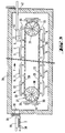
- each support plate to membrane 6 comprises a frame, for example rectangular 14, made of bars or profiled tubes.
- the frame 14 is, in the case shown, mounted on a frame support 15 which, as such, is provided with suitable means for the transport through the oven.
- Membrane 8 made of heat resistant fabric is stretched over frame 14.
- the heat-resistant fabric can, for example, be a fiberglass fabric. Woven structures of metallic fibers heat resistant have proven particularly suitable for this purpose.
- the membrane 8 must be kept under a tension such that it forms a flat surface as much as possible. Following thermal expansion, the membrane 8 of course loses tension and sags somewhat under the influence of the weight of the glass sheet. As already mentioned in detail previously, this bending however does not harm the glass sheet with regard to possible deformations, because the glass sheet, due to its low camber, rests entirely on the membrane, so that the load per unit area is very uniform.
- a membrane structure made up of two layers of fabric superimposed, namely a woven lower fabric 17 and a woven upper fabric or 18 mesh has proven to be particularly satisfactory.
- the thickness of woven fabric lower 17 must guarantee the necessary tension of the membrane, while the thickness of woven or mesh fabric greater than 18 is selected for constitute an optimum substrate for glass sheets.
- the fabric 17 is arranged and stretched so that the warp threads extend in the direction of the forces ensuring the tension.
- the woven fabric 17 is attached to one end of the chain son by means of a slat 19 on the outer side surface of the frame 14.
- a slat metal 20 is permanently connected to the fabric 17.
- the metal slat 20 is provided with hook-shaped tension projections 21.
- Tension projections hook-shaped 21 engage behind rotating cylindrical discs 22 which are mounted in eccentric rotation on the frame 14. By turning these cylindrical discs 22 mounted eccentrically, the fabric 17 can be stretched.
- a fabric with mesh which, as such, has greater elasticity than a fabric woven and whose fine structure adapts accordingly appropriately to the glass surface.
- the rectangular mesh fabric 18 is also attached along on one side to the frame 14 by means of a metal slat 24, while the side opposite, like the woven fabric 17, is provided with a tension batten by means of from which the mesh 18 is stretched.
- the plan dimensions of the frame 14 and of the membrane 8 must be chosen such that the internal dimensions of the frame 14 are larger than the plan dimensions of the glass sheets to be transported, so that these rest entirely on the free stretched area of the membrane 8 to inside the frame 14.
- FIG. 3 A first embodiment of an equipped oven a transport system suitable for this purpose is illustrated in Figure 3.
- the transport device consists essentially of an endless chain conveyor belt 27 comprising an upper strand 28 for transporting the glass sheets in the direction of arrow F and a strand lower 29 for the return of the empty membrane support plates 6.
- the chain conveyor belt 27 runs on chain wheels corresponding 30 and 31, one of which is rotated, through of a drive shaft extending outwards, by a mechanism drive installed outside the enclosure 26 of the oven.
- Each tray membrane support 6 is fixed by balusters 33 on the strip chain conveyor 27.
- the membrane support plates 6 are loaded with glass sheets 2 through opening 35 which can be closed by a door 36.
- the glass sheets 2 which are conveyed by example on a roller conveyor 38 to near the furnace, are positioned on this roller conveyor 38, that is to say that they are brought to a predetermined position with precision.
- the positioning precise at this point is important for the whole subsequent process, in particularly for the bending process carried out downstream of the furnace.
- suction pad 39 which is in a defined position above the glass sheet 2 positioned, glass sheet 2 is lifted from the conveyor roller 38.
- the glass sheet 2 is transported in the oven from a predetermined distance precisely and is deposited in this oven on a membrane support plate 6 which, at the moment of the deposition of the glass sheet 2, also occupies a defined position with precision.
- the removal of hot glass sheets at the end of the oven is made through the opening 42 by means of the suction cup 44 horizontally movable.
- new than the suction cup 44 and the membrane support plate 6 concerned occupy, at the time of the transfer of the hot glass sheet, each a relative position determined with precision.
- Position control necessary for this purpose can also be provided by known means with relatively high accuracy.
- FIG. 4 illustrates another embodiment of an oven in accordance with the invention equipped with another transport system, in which the trays of membrane support 6, after removal of the glass sheets 2 are returned to the outside of the oven 46 toward the cold end thereof.
- the membrane support plate 6 rests on two support rails 47 which extends through side slots 48 between the infrastructure and the superstructure of the oven 46 to the outside of the oven enclosure. Outside of the oven, these support rails 47 rest on conveyor belts narrow 50 which have the shape of endless bands and which are driven to a speed set by idler rollers 51 driven.
- On the tapes conveyors 50 are fixed retaining members forming a U 52 on which the support rails 47 of the membrane support plates 6 lie in a respective fixed position.
- the suction cup picking up the glass sheet should then simply be positioned with reference to the membrane support plate 6, which can however be easily achieved for example by a mechanical coupling between the membrane support plate and suction cup at the time of recovery of the glass sheet.
- the support plate to membrane 6 is removed from the oven by the conveyor belt 50 and then by a other device not shown, the support rails 47 being brought on rigid supports 53 of a carriage 54.
- the carriage 54 is movable on wheels 55 on rails 56 transverse to the longitudinal axis of the oven 46 towards two end positions. While the carriage 54, in the end position shown in the drawings, receives the membrane support plate 6 coming from the oven 46, the membrane support plate 6, in the other end position of the carriage 54, is transferred to conveyor belts by means from which the membrane support plates 6 are transported and brought back at the cold end of the oven. They are brought there again by means of a transverse transport system corresponding to the trolley system described in a position in which they are taken up by the bands conveyors 50 and transported again through the oven 46.
- FIG. 5 illustrates an embodiment of the invention within a furnace 60 of which the longitudinal axis is vertical.
- Such an oven can have various advantages. First of all, it saves considerable space, at least by one point surface view. In addition, it allows faster heating of the sheets glass due to the higher convection heating part in this type of oven. This faster heating is of course particularly interesting in the case of thin glass sheets.
- arrival cold glass sheets 2 this can be done as in the case of tunnel ovens described above. In Figure 5, this is done using a suction cup 61.
- the glass sheets 2 are brought conventionally to a bending station 62 and then to a station quenching 63. In FIG. 5, the bending station is located within the furnace 60.
- the glass sheets are removed from the oven in the same way as in the tunnel kilns.
- the support plates 6 follow a vertical movement in direction F, i.e. from bottom to top.
- the sheets of glass released towards the bending station 62 the support plates 6 are returned to the receiving position for cold glass sheets.
- the movement of these trays is then done in a vertical direction from the top down.
- Devices authorizing the movement of the support plates 6 in a vertical direction, these retaining a horizontal position especially when they support a glass sheet 2 are similar to those described previously in the case of horizontal displacements in the ovens tunnels.
- Heating can be obtained by resistors electric 64 advantageously coupled to non-ventilating devices shown in the figures. These devices cause air circulation in the directions indicated by the arrows 65 and can contribute to further increase the heating rate.
- the arrival of the glass sheets 2 can be done at the upper level and their exit at the lower level.
- the movement of the support plates during the heating phase and so that of the glass sheets 2 is done in a vertical direction downward which can further promote convection heating.
Landscapes
- Chemical & Material Sciences (AREA)
- Engineering & Computer Science (AREA)
- Materials Engineering (AREA)
- Organic Chemistry (AREA)
- Physics & Mathematics (AREA)
- Thermal Sciences (AREA)
- Re-Forming, After-Treatment, Cutting And Transporting Of Glass Products (AREA)
- Tunnel Furnaces (AREA)
- Furnace Charging Or Discharging (AREA)
Applications Claiming Priority (2)
| Application Number | Priority Date | Filing Date | Title |
|---|---|---|---|
| DE4438261 | 1994-10-26 | ||
| DE4438261A DE4438261C1 (de) | 1994-10-26 | 1994-10-26 | Durchlaufofen zum Erwärmen von Glasscheiben auf Biege- und/oder Vorspanntemperatur |
Publications (3)
| Publication Number | Publication Date |
|---|---|
| EP0709343A2 EP0709343A2 (fr) | 1996-05-01 |
| EP0709343A3 EP0709343A3 (fr) | 1996-08-28 |
| EP0709343B1 true EP0709343B1 (fr) | 2000-01-12 |
Family
ID=6531756
Family Applications (1)
| Application Number | Title | Priority Date | Filing Date |
|---|---|---|---|
| EP95402287A Expired - Lifetime EP0709343B1 (fr) | 1994-10-26 | 1995-10-13 | Fours à passage continu pour le chauffage de feuilles de verre à la température de bombage et/ou de trempe |
Country Status (8)
| Country | Link |
|---|---|
| US (1) | US5830253A (sv) |
| EP (1) | EP0709343B1 (sv) |
| JP (1) | JP4243359B2 (sv) |
| KR (1) | KR100415202B1 (sv) |
| DE (2) | DE4438261C1 (sv) |
| ES (1) | ES2143605T3 (sv) |
| FI (1) | FI120683B (sv) |
| PT (1) | PT709343E (sv) |
Families Citing this family (22)
| Publication number | Priority date | Publication date | Assignee | Title |
|---|---|---|---|---|
| DE19744440A1 (de) * | 1997-10-08 | 1999-04-15 | Lingl Anlagenbau | Röhrenförmiger Ofen zum Brennen von Keramikprodukten |
| IT249695Y1 (it) * | 2000-01-13 | 2003-05-28 | Fata Automation | Impianto di trasporto con trasportatore dotato di rulli folli di appoggio di elementi di trasporto |
| DE20104463U1 (de) * | 2001-03-15 | 2002-07-25 | Christ Otto Ag | Plattenförderer zum Bewegen von Lasten |
| WO2002101780A1 (fr) * | 2001-05-30 | 2002-12-19 | Matsushita Electric Industrial Co., Ltd. | Procede de fabrication d'affichages a decharge gazeuse, support de table et son procede de fabrication |
| US6824584B2 (en) | 2001-07-03 | 2004-11-30 | Donald C. Young | Ammonium phosphate/phosphite fertilizer compound |
| DE10335453B4 (de) * | 2003-08-02 | 2007-03-01 | Schott Ag | Verfahren zum Biegen von Flachglas und zugehörige Biegevorrichtung |
| DE10337304B4 (de) * | 2003-08-14 | 2008-07-03 | Sms Elotherm Gmbh | Erwärmunganlage |
| US8105367B2 (en) | 2003-09-29 | 2012-01-31 | Smith & Nephew, Inc. | Bone plate and bone plate assemblies including polyaxial fasteners |
| US8382807B2 (en) | 2005-07-25 | 2013-02-26 | Smith & Nephew, Inc. | Systems and methods for using polyaxial plates |
| EP1919385B1 (en) | 2005-07-25 | 2014-08-20 | Smith & Nephew, Inc. | Polyaxial plates |
| DE102006024484B3 (de) * | 2006-05-26 | 2007-07-19 | Saint-Gobain Sekurit Deutschland Gmbh & Co. Kg | Vorrichtung und Verfahren zum Biegen von Glasscheiben |
| DE102007007974B4 (de) * | 2006-12-01 | 2013-04-18 | Saint-Gobain Sekurit Deutschland Gmbh & Co. Kg | Vorrichtung zum Erhitzen und Verfahren zum Erhitzen und/oder Biegen von auf Transportformen aufliegenden Glasscheiben |
| JP5376631B2 (ja) * | 2008-11-20 | 2013-12-25 | 日本碍子株式会社 | 粉体焼成用縦型焼成炉 |
| JP5454935B2 (ja) * | 2010-10-01 | 2014-03-26 | 株式会社日本製鋼所 | 連続式熱処理炉 |
| CN102476910A (zh) | 2010-11-23 | 2012-05-30 | 洛阳兰迪玻璃机器股份有限公司 | 一种狭缝式真空玻璃封接装置 |
| CN103717179B (zh) | 2011-06-15 | 2017-08-08 | 史密夫和内修有限公司 | 可变角度锁定植入物 |
| KR20130049080A (ko) * | 2011-11-03 | 2013-05-13 | 삼성디스플레이 주식회사 | 회전식 박막 증착 장치 및 그것을 이용한 박막 증착 방법 |
| KR101366694B1 (ko) * | 2012-09-12 | 2014-02-25 | 한국성전(주) | 투명도전성 필름 전(前)열처리 장치 |
| KR101492253B1 (ko) * | 2013-02-26 | 2015-02-13 | 주식회사 좋은기술 | 진공창 제조 설비의 봉착로 장치 |
| GB2557840B (en) | 2015-09-18 | 2021-07-21 | Smith & Nephew Inc | Bone plate |
| RU2714744C1 (ru) * | 2017-01-30 | 2020-02-19 | Сэн-Гобэн Гласс Франс | Способ гибки стеклянного листа |
| CN113341523B (zh) * | 2021-06-07 | 2022-12-09 | 西安康拓医疗技术股份有限公司 | 一种用于高温加工环境的窗口镜装置 |
Family Cites Families (12)
| Publication number | Priority date | Publication date | Assignee | Title |
|---|---|---|---|---|
| FR321171A (fr) * | 1902-07-21 | 1903-02-26 | Lessing Kurt | Genre de dispositifs de sureté s'appliquant aux presses hydrauliques pour empecher le piston de dépasser les limites de sa course |
| FR596657A (fr) * | 1925-02-26 | 1925-10-29 | Perfectionnements aux appareils pour fabriquer en plaques et recuire les verres de vitres | |
| FR41519E (fr) * | 1932-03-03 | 1933-01-28 | Herzogenrather Glaswerke Biche | Table de réception et de transport pour plaques de verre laminées |
| US2111370A (en) * | 1936-12-19 | 1938-03-15 | Pittsburgh Plate Glass Co | Apparatus for bending glass sheets |
| NL299685A (sv) * | 1962-11-19 | |||
| FR1414887A (fr) * | 1964-09-08 | 1965-10-22 | Saint Gobain | Procédé pour supporter un matériau en forme de feuille |
| DE2741098A1 (de) * | 1977-09-13 | 1979-03-22 | Heinrich Patalon | Vorrichtung zum thermischen vorspannen von glasscheiben, insbesondere durchlaufofen |
| DE3721863A1 (de) * | 1987-07-02 | 1989-01-12 | Ver Glaswerke Gmbh | Haltevorrichtung mit saugwirkung fuer glasscheiben und verwendung der haltevorrichtung bei einem verfahren zum biegen von glasscheiben |
| US4983202A (en) * | 1990-02-27 | 1991-01-08 | Libbey-Owens-Ford Co. | Glass sheet heating furnace and method of using |
| DE4030222C1 (sv) * | 1990-09-25 | 1991-11-14 | Vegla Vereinigte Glaswerke Gmbh, 5100 Aachen, De | |
| DE4215285C1 (sv) * | 1992-05-09 | 1993-08-19 | Vegla Vereinigte Glaswerke Gmbh, 5100 Aachen, De | |
| JPH066237U (ja) * | 1992-06-29 | 1994-01-25 | セントラル硝子株式会社 | ガラス板用パレット |
-
1994
- 1994-10-26 DE DE4438261A patent/DE4438261C1/de not_active Expired - Fee Related
-
1995
- 1995-10-13 DE DE69514480T patent/DE69514480T2/de not_active Expired - Lifetime
- 1995-10-13 EP EP95402287A patent/EP0709343B1/fr not_active Expired - Lifetime
- 1995-10-13 ES ES95402287T patent/ES2143605T3/es not_active Expired - Lifetime
- 1995-10-13 PT PT95402287T patent/PT709343E/pt unknown
- 1995-10-25 JP JP27801795A patent/JP4243359B2/ja not_active Expired - Lifetime
- 1995-10-25 US US08/547,864 patent/US5830253A/en not_active Expired - Lifetime
- 1995-10-25 FI FI955083A patent/FI120683B/sv not_active IP Right Cessation
- 1995-10-26 KR KR1019950038031A patent/KR100415202B1/ko not_active IP Right Cessation
Also Published As
| Publication number | Publication date |
|---|---|
| EP0709343A3 (fr) | 1996-08-28 |
| FI955083A (sv) | 1996-04-27 |
| JP4243359B2 (ja) | 2009-03-25 |
| US5830253A (en) | 1998-11-03 |
| DE69514480T2 (de) | 2000-07-06 |
| KR100415202B1 (ko) | 2004-04-28 |
| DE4438261C1 (de) | 1995-09-21 |
| JPH08208254A (ja) | 1996-08-13 |
| DE69514480D1 (de) | 2000-02-17 |
| EP0709343A2 (fr) | 1996-05-01 |
| FI120683B (sv) | 2010-01-29 |
| ES2143605T3 (es) | 2000-05-16 |
| KR960014041A (ko) | 1996-05-22 |
| FI955083A0 (sv) | 1995-10-25 |
| PT709343E (pt) | 2000-06-30 |
Similar Documents
| Publication | Publication Date | Title |
|---|---|---|
| EP0709343B1 (fr) | Fours à passage continu pour le chauffage de feuilles de verre à la température de bombage et/ou de trempe | |
| EP0133114B1 (fr) | Installation de bombage et de trempe de feuilles de verre | |
| FR2568868A1 (fr) | Installation et procede pour bomber des plaques de verre | |
| EP0169770A1 (fr) | Procédé et dispositif pour le bombage de plaques de verre en position horizontale | |
| FR2612917A1 (fr) | Procede et appareillage de profilage de feuilles de verre, notamment de glaces pour automobiles | |
| FR2604992A1 (fr) | Bombage et trempe de plaques de verre defilant sur un lit de conformation courbe dans la direction de defilement | |
| FR2515166A1 (fr) | Moule a vide sous forme de caisse deformable pour la mise en forme de feuilles de verre | |
| EP2021295B1 (fr) | Chauffage d'objets dans une ligne de four | |
| EP0474531B1 (fr) | Procédé et dispositif d'obtention de feuilles de verre bombées | |
| FR2478066A1 (fr) | Procede et dispositif pour le formage de feuilles de verre a l'aide d'un moule a vide deformable | |
| EP0415826B1 (fr) | Dispositif de bombage de feuilles de verre en position horizontale | |
| FR1465011A (fr) | Procédé et installation pour la cuisson des objets en matière céramique | |
| FR2618774A1 (fr) | Systeme convoyeur de bouteilles pour transporter des bouteilles chaudes d'une machine de formage jusqu'a un four de recuisson | |
| BE897061A (fr) | Support pour feuilles de verre chaudes de contour irregulier avant courbure | |
| FR2465692A1 (fr) | Procede et dispositif de faconnage de feuilles de verre a l'aide de moules de formes differentes | |
| FR2546503A1 (fr) | Support a depression a chambres multiples, utilise pour la mise en forme de feuilles de verre, avec des moyens d'isolement des chambres a vide voisines | |
| BE1000065A6 (fr) | Procede et appareil de cambrage de feuilles de verre. | |
| FR2552074A1 (fr) | Moule a depression pour la mise en forme de feuilles de verre | |
| FR2516502A1 (fr) | Procede et dispositif pour extraire des feuilles de verre cintrees et trempees d'un poste de refroidissement | |
| FR2552754A1 (fr) | Procede pour donner des formes compliquees a des feuilles de verre a l'aide d'un moule elevateur special | |
| EP0928284B1 (fr) | Four a rouleaux pour le chauffage de vitrages | |
| EP3048892A1 (fr) | Procédé de cuisson de produits de boulangerie, viennoiserie et pâtisserie avec préchauffage direct, et ses dispositifs de mise en oeuvre | |
| EP0244305B1 (fr) | Transfert d'objets en plaques d'un convoyeur à un autre dispositif et application au bombage de plaques de verre | |
| EP0463971B1 (fr) | Procédé et dispositif d'obtention de feuilles de verre bombées et trempées | |
| FR2487058A1 (fr) | Four a parois chauffantes interchangeables pour le traitement thermique de feuilles de verre |
Legal Events
| Date | Code | Title | Description |
|---|---|---|---|
| PUAI | Public reference made under article 153(3) epc to a published international application that has entered the european phase |
Free format text: ORIGINAL CODE: 0009012 |
|
| AK | Designated contracting states |
Kind code of ref document: A2 Designated state(s): BE CH DE ES FR GB IT LI LU PT |
|
| PUAL | Search report despatched |
Free format text: ORIGINAL CODE: 0009013 |
|
| AK | Designated contracting states |
Kind code of ref document: A3 Designated state(s): BE CH DE ES FR GB IT LI LU PT |
|
| 17P | Request for examination filed |
Effective date: 19970123 |
|
| GRAG | Despatch of communication of intention to grant |
Free format text: ORIGINAL CODE: EPIDOS AGRA |
|
| 17Q | First examination report despatched |
Effective date: 19990318 |
|
| GRAG | Despatch of communication of intention to grant |
Free format text: ORIGINAL CODE: EPIDOS AGRA |
|
| GRAH | Despatch of communication of intention to grant a patent |
Free format text: ORIGINAL CODE: EPIDOS IGRA |
|
| GRAH | Despatch of communication of intention to grant a patent |
Free format text: ORIGINAL CODE: EPIDOS IGRA |
|
| GRAA | (expected) grant |
Free format text: ORIGINAL CODE: 0009210 |
|
| AK | Designated contracting states |
Kind code of ref document: B1 Designated state(s): BE CH DE ES FR GB IT LI LU PT |
|
| REG | Reference to a national code |
Ref country code: CH Ref legal event code: EP |
|
| REF | Corresponds to: |
Ref document number: 69514480 Country of ref document: DE Date of ref document: 20000217 |
|
| ITF | It: translation for a ep patent filed |
Owner name: RACHELI & C. S.R.L. |
|
| REG | Reference to a national code |
Ref country code: CH Ref legal event code: NV Representative=s name: KIRKER & CIE SA |
|
| GBT | Gb: translation of ep patent filed (gb section 77(6)(a)/1977) |
Effective date: 20000328 |
|
| REG | Reference to a national code |
Ref country code: ES Ref legal event code: FG2A Ref document number: 2143605 Country of ref document: ES Kind code of ref document: T3 |
|
| REG | Reference to a national code |
Ref country code: PT Ref legal event code: SC4A Free format text: AVAILABILITY OF NATIONAL TRANSLATION Effective date: 20000411 |
|
| PLBE | No opposition filed within time limit |
Free format text: ORIGINAL CODE: 0009261 |
|
| STAA | Information on the status of an ep patent application or granted ep patent |
Free format text: STATUS: NO OPPOSITION FILED WITHIN TIME LIMIT |
|
| 26N | No opposition filed | ||
| REG | Reference to a national code |
Ref country code: GB Ref legal event code: IF02 |
|
| REG | Reference to a national code |
Ref country code: DE Ref legal event code: R082 Ref document number: 69514480 Country of ref document: DE Representative=s name: LENDVAI, TOMAS, DIPL.-CHEM. DR.RER.NAT, DE Ref country code: DE Ref legal event code: R082 Ref document number: 69514480 Country of ref document: DE Representative=s name: TOMAS LENDVAI, DE |
|
| PGFP | Annual fee paid to national office [announced via postgrant information from national office to epo] |
Ref country code: LU Payment date: 20131010 Year of fee payment: 19 |
|
| PGFP | Annual fee paid to national office [announced via postgrant information from national office to epo] |
Ref country code: ES Payment date: 20140911 Year of fee payment: 20 |
|
| PGFP | Annual fee paid to national office [announced via postgrant information from national office to epo] |
Ref country code: FR Payment date: 20141016 Year of fee payment: 20 Ref country code: DE Payment date: 20141007 Year of fee payment: 20 Ref country code: CH Payment date: 20141014 Year of fee payment: 20 Ref country code: GB Payment date: 20141008 Year of fee payment: 20 |
|
| PGFP | Annual fee paid to national office [announced via postgrant information from national office to epo] |
Ref country code: PT Payment date: 20141007 Year of fee payment: 20 |
|
| PGFP | Annual fee paid to national office [announced via postgrant information from national office to epo] |
Ref country code: IT Payment date: 20141014 Year of fee payment: 20 |
|
| PGFP | Annual fee paid to national office [announced via postgrant information from national office to epo] |
Ref country code: BE Payment date: 20141030 Year of fee payment: 20 |
|
| PG25 | Lapsed in a contracting state [announced via postgrant information from national office to epo] |
Ref country code: LU Free format text: LAPSE BECAUSE OF NON-PAYMENT OF DUE FEES Effective date: 20141013 |
|
| REG | Reference to a national code |
Ref country code: DE Ref legal event code: R071 Ref document number: 69514480 Country of ref document: DE |
|
| REG | Reference to a national code |
Ref country code: PT Ref legal event code: MM4A Free format text: MAXIMUM VALIDITY LIMIT REACHED Effective date: 20151013 |
|
| REG | Reference to a national code |
Ref country code: CH Ref legal event code: PL |
|
| REG | Reference to a national code |
Ref country code: GB Ref legal event code: PE20 Expiry date: 20151012 |
|
| REG | Reference to a national code |
Ref country code: ES Ref legal event code: FD2A Effective date: 20160126 |
|
| PG25 | Lapsed in a contracting state [announced via postgrant information from national office to epo] |
Ref country code: GB Free format text: LAPSE BECAUSE OF EXPIRATION OF PROTECTION Effective date: 20151012 |
|
| PG25 | Lapsed in a contracting state [announced via postgrant information from national office to epo] |
Ref country code: PT Free format text: LAPSE BECAUSE OF EXPIRATION OF PROTECTION Effective date: 20151020 |
|
| PG25 | Lapsed in a contracting state [announced via postgrant information from national office to epo] |
Ref country code: ES Free format text: LAPSE BECAUSE OF EXPIRATION OF PROTECTION Effective date: 20151014 |