EP0709262B1 - Gonfleur pour coussin d'air avec des raccords de boítier assemblés par sertissage - Google Patents
Gonfleur pour coussin d'air avec des raccords de boítier assemblés par sertissage Download PDFInfo
- Publication number
- EP0709262B1 EP0709262B1 EP95307672A EP95307672A EP0709262B1 EP 0709262 B1 EP0709262 B1 EP 0709262B1 EP 95307672 A EP95307672 A EP 95307672A EP 95307672 A EP95307672 A EP 95307672A EP 0709262 B1 EP0709262 B1 EP 0709262B1
- Authority
- EP
- European Patent Office
- Prior art keywords
- housing
- side wall
- base
- annular
- wall
- Prior art date
- Legal status (The legal status is an assumption and is not a legal conclusion. Google has not performed a legal analysis and makes no representation as to the accuracy of the status listed.)
- Expired - Lifetime
Links
- 239000000463 material Substances 0.000 claims description 55
- 229910052751 metal Inorganic materials 0.000 claims description 26
- 239000002184 metal Substances 0.000 claims description 26
- 230000000994 depressogenic effect Effects 0.000 claims description 14
- 230000002093 peripheral effect Effects 0.000 claims description 8
- 238000003466 welding Methods 0.000 claims description 5
- 239000007789 gas Substances 0.000 description 113
- 238000007789 sealing Methods 0.000 description 39
- 238000002485 combustion reaction Methods 0.000 description 24
- 229910000831 Steel Inorganic materials 0.000 description 22
- 230000004913 activation Effects 0.000 description 21
- 229910052782 aluminium Inorganic materials 0.000 description 21
- XAGFODPZIPBFFR-UHFFFAOYSA-N aluminium Chemical compound [Al] XAGFODPZIPBFFR-UHFFFAOYSA-N 0.000 description 21
- 239000010959 steel Substances 0.000 description 21
- 238000005304 joining Methods 0.000 description 20
- 238000004891 communication Methods 0.000 description 15
- 230000002708 enhancing effect Effects 0.000 description 14
- 239000008188 pellet Substances 0.000 description 14
- 239000007787 solid Substances 0.000 description 9
- 238000000034 method Methods 0.000 description 8
- 230000009471 action Effects 0.000 description 7
- 239000000356 contaminant Substances 0.000 description 7
- 238000002788 crimping Methods 0.000 description 7
- 238000001914 filtration Methods 0.000 description 7
- 238000005242 forging Methods 0.000 description 7
- 235000012431 wafers Nutrition 0.000 description 7
- 230000006835 compression Effects 0.000 description 3
- 238000007906 compression Methods 0.000 description 3
- 230000003319 supportive effect Effects 0.000 description 2
- 238000010276 construction Methods 0.000 description 1
- 238000007599 discharging Methods 0.000 description 1
- 238000012986 modification Methods 0.000 description 1
- 230000004048 modification Effects 0.000 description 1
- 230000008569 process Effects 0.000 description 1
- 230000002787 reinforcement Effects 0.000 description 1
- 239000003566 sealing material Substances 0.000 description 1
- 238000005728 strengthening Methods 0.000 description 1
- 230000001960 triggered effect Effects 0.000 description 1
Images


Classifications
-
- B—PERFORMING OPERATIONS; TRANSPORTING
- B60—VEHICLES IN GENERAL
- B60R—VEHICLES, VEHICLE FITTINGS, OR VEHICLE PARTS, NOT OTHERWISE PROVIDED FOR
- B60R21/00—Arrangements or fittings on vehicles for protecting or preventing injuries to occupants or pedestrians in case of accidents or other traffic risks
- B60R21/02—Occupant safety arrangements or fittings, e.g. crash pads
- B60R21/16—Inflatable occupant restraints or confinements designed to inflate upon impact or impending impact, e.g. air bags
- B60R21/26—Inflatable occupant restraints or confinements designed to inflate upon impact or impending impact, e.g. air bags characterised by the inflation fluid source or means to control inflation fluid flow
- B60R21/264—Inflatable occupant restraints or confinements designed to inflate upon impact or impending impact, e.g. air bags characterised by the inflation fluid source or means to control inflation fluid flow using instantaneous generation of gas, e.g. pyrotechnic
- B60R21/2644—Inflatable occupant restraints or confinements designed to inflate upon impact or impending impact, e.g. air bags characterised by the inflation fluid source or means to control inflation fluid flow using instantaneous generation of gas, e.g. pyrotechnic using only solid reacting substances, e.g. pellets, powder
Definitions
- the present invention relates to air bag inflators and more particularly air bag inflators having a housing or canister with crimp-formed joints.
- the air bag inflator having a unique housing or canister construction in accordance with the present invention employs crimped-formed joints formed between a base and inner and outer side walls to provide a low cost sealed enclosure for containing an ignition system, a gas generant and a filter.
- U.S. Patent No. 4,116,466 discloses an air bag inflator employing a threaded connecting joint between a pair of opposite housing sections.
- U.S. Patent No. 4,131,299 discloses a gas generator utilizing a housing having a threaded interconnection between opposite housing wall portions and a threaded closure cap for a central ignition chamber.
- U.S. Patent No. 4,370,930 discloses an end cap for a propellent container which has a rolled, crimped-edge for joining the cap to the end of a hollow canister.
- 4,530,516 discloses a reduced-weight, air bag inflator housing, having a hollow steel center ring member and a separate retaining ring for holding the stamping formed pressure containment components in place.
- U.S. Patent No. 4,734,265 discloses a gas generator for safety belt tightening equipment wherein an ignition plug is held in place by a crimped or press fitted section of a housing wall section.
- U.S. Patent No. 5,139,280 discloses a cold-gas, pyrotechnic generator including a cover and base that are friction welded together.
- 5,275,431 discloses an air bag inflator assembly wherein a support plate is provided with a retainer crimped to a component of an inflator canister for securing the inflator canister in place.
- DE-C-4 102 275 discloses an airbag inflation housing corresponding to the preamble of claim 1.
- Another object of the present invention is to provide a new and improved air bag inflator housing which utilizes a stamped out, forged or cold drawn, hollow, metal rivet like, inner wall forming a central ignition chamber.
- Another object of the present invention is to provide a new and improved housing for an air bag inflator having an inner ignition chamber wall with a reduced thickness which may be crimp-formed to join and seal with an annular housing base.
- Another object of the present invention is to provide a new and improved air bag inflator housing which utilizes a central rivet-like element closed at one end and open at the other for receiving an ignition system, and which element provides structural reinforcement for central portions of a top wall and an opposite base.
- Still another object of the present invention is to provide a new and improved inflator housing which utilizes crimp-formed joints between side walls and opposite end walls or top and base walls of the housing.
- Yet another object of the present invention is to provide a new and improved air bag inflator housing having only a pair of side walls and utilizing crimped joints between the side walls and end walls to define an inner central ignition chamber and a surrounding outer combustion/filter chamber.
- Another object of the present invention is to provide a new and improved air bag inflator housing having crimped joints between end walls and side walls which allows the use of compressible seal rings for preventing filter blow-by during the combustion process and providing a hermetic seal against the outside environment.
- Yet another object of the present invention is to provide a new and improved air bag inflator housing which minimizes the number of hermetic or air-tight seals that are required and utilizing pressure-crimped joints between inner and outer side walls and opposite end walls.
- a new and improved air bag inflator having a diffuser housing including concentric inner and outer, ported side walls and a pair of opposite end walls joined therewith to form a sealed enclosure for containing solid gas generant material and an ignition system therefor.
- the inner side wall forms a central ignition chamber for an ignition system has a plurality of ignition wall ports in direct communication with an annular combination combustion and filter-containing chamber surrounding and formed around the ignition chamber for holding a quantity of solid gas generant material and a filter.
- the outer side wall has a plurality of gas discharging, diffuser ports for directing the gas generated in the inflator housing to rapidly inflate an associated air bag.
- the inner side wall and the outer side wall are joined to at least one of the end walls for sealing and closing the housing by means of a crimp-formed joint.
- This enables the housing to be constructed of relatively low-cost metal tube, sheet and plate materials and provides for a faster and easier assembly of the inflator and internal components.
- the inner side wall comprises a depending cylindrical skirt of a rivet-like ignition containing housing element closed at the upper end and open at the lower end to receive the ignition system of the inflator.
- the outer side wall is integrally joined to the outer periphery of an annular top wall having a central opening aligned with a similar opening coaxially aligned formed in an annular base or bottom wall spaced from the top wall.
- the ported inner side wall of the rivet-like element extends downwardly through the aligned openings in both the top wall and the base, and is formed with a stepped lower end portion comprising a thin wall section below an annular stop surface which supports the base when the thin wall section is deformed radially outwardly in a crimp-forming operation for securing the inner side wall and base together.
- Various types of crimp-forming operations are provided around the outer periphery of the annular base and a lower end portion of the outer side wall to join these members together to complete and sealingly close the housing.
- the housing may be constructed of relatively low-cost metal tube, sheet and plate materials and may be assembled in a faster and easier process, realizing great savings in time and cost.
- FIGS. 1 and 2 therein is illustrated a first embodiment of a new and improved air bag inflator for rapidly inflating an air bag (not shown) upon triggered actuation constructed in accordance with the features of the present invention and referred to generally by the reference numeral 100.
- Inflator 100 includes a housing or canister 102 formed of strong, lightweight metal such as aluminum or steel sheet or plate material having an upper, inverted cup-shaped diffuser cover 104 and a generally circular, annular base 106 having a central opening 107 formed thereon and joined to form a sealed enclosure or housing for containing a quantity of solid, gas generant material 108 in the form of pellets or wafers which rapidly combust to provide a necessary volume of inflation gas for the rapid deployment of an air bag in communication with the inflator 100.
- a housing or canister 102 formed of strong, lightweight metal such as aluminum or steel sheet or plate material having an upper, inverted cup-shaped diffuser cover 104 and a generally circular, annular base 106 having a central opening 107 formed thereon and joined to form a sealed enclosure or housing for containing a quantity of solid, gas generant material 108 in the form of pellets or wafers which rapidly combust to provide a necessary volume of inflation gas for the rapid deployment of an air bag in communication with the inflat
- the diffuser cover 104 includes an annular top wall 110 and an integrally formed, downwardly depending, cylindrical outer side wall 112.
- the cylindrical outer wall 112 and the annular circular top wall 110 may be formed of sheet aluminum or steel, and the outer side wall 112 is provided with a plurality of gas discharge diffuser ports 116 arranged in a ring around the periphery for directing the gas generated in the housing 102 to flow radially outwardly into an air bag (not shown) as indicated by the radially extending arrows A.
- the annular top wall 110 is formed with a circular opening 109 at the center in coaxial alignment with the central opening 107 in the annular base 106.
- the top wall 110 is formed with an annular, downwardly depressed shoulder 111 at a level below the upper surface of an outer portion of the top wall extending radially outwardly thereof and immediately encircling the central opening 109.
- the inflator 100 also includes a centrally disposed, cylindrical inner side wall 120 in coaxial alignment with the outer side wall 112.
- a rivet-like ignition housing member 125 (FIG. 11) fabricated of metal in a forging, deep drawing, or stamping operation includes a circular upper end wall 123 integrally joining the depending inner side wall 120 and closing off the upper end of a central ignition chamber 124 provided in the housing 102.
- the circular upper end wall 123 extends radially outwardly of the central opening 109 a short distance and is sealed with the shoulder surface 111 of the top wall 110 by an annular weld 122, a hermetic seal ring, gasket, or other sealing and joining method.
- the outer upper surfaces of the top wall 110 and the upper end wall 123 of the rivet-like housing member 125 are substantially aligned as shown to provide a flat upper surface overall for the housing 102.
- the ignition chamber 124 contains an electrically activated ignition squib 126 and a charge 128 of an ignition-enhancing material contained within an igniter cup 129 positioned in the upper end portion of the chamber.
- the ignition squib 126 mounted in an adapter plug 142 is electrically activated and includes a pair of downwardly depending electrical terminals 126a adapted for connection to an external electrical activation system of a motor vehicle.
- the inner side wall 120 is formed with a plurality of ignition ports 130 in direct communication between the ignition chamber 124 and an outer, surrounding, annular, combination combustion and filter-containing chamber 132.
- the gas generant material 108 is arranged in an annular mass in an inner portion of the chamber 132 and is encircled by an outer, annular gas filter 134 mounted adjacent the inside surface of the outer side wall 112.
- the ignition chamber wall ports 130 direct hot combustion products from the ignition squib 126 and the ignition enhancing material 128 into the annulus of gas generant pellets 108 as indicated by the arrows B.
- annular gas filters 134 may be utilized; and in general, the filter includes a large area, cylindrically-shaped, inner face or inlet side, for receiving hot combustion products generated in the housing 102 and an outer surface in facing confrontation with the diffuser discharge ports 116 in the ported outer side wall 112.
- the diffuser wall ports 116 are sealed off against the entry of outside contaminants during the life of the inflator 100 before activation by means of a thin adhesively secured, sealing tape 136, which tape is readily ruptured by a predetermined gas pressure when activation of the inflator 100 takes place.
- Upper and lower annular end surfaces of the filter 134 may be sealed against the underside of the top wall 110 and the upper surface of the base wall 106, respectively, by a pair of resilient, annular, sealing rings or gaskets 138 and 140 in order to prevent blow-by of the hot gases around the upper and lower annular end faces of the gas filter 134.
- the sealing rings 138 and 140 ensure good filtering action by containing the gas flow within the available flow cross-section of the gas filter 134 until the gas exits the outer face to reach the diffuser wall gas discharge ports 116.
- a thin wall segment at a lower end portion 120a of the cylindrical inner side wall 120 projects downwardly below the underside of the annular base 106 and is adapted to be crimp-formed over and radially outwardly (Arrows C - FIG. 1) toward an adjacent inwardly depressed annular recess 113 on the underside surface of the base around the central opening 107.
- An annular step or shoulder 127 is formed at the juncture of a relatively thick upper wall portion of the inner side wall 120 and the relatively thin wall lower end portion 120a.
- the annular step 127 acts as a stop to support the recessed surface portion 113 of the base 106 as the thin wall segment 120a is crimp-formed over radially outwardly (Arrows C - FIG. 2) toward the closing position of FIG. 2 to complete the sealing or closing of the housing 102 around the lower end of the rivet-like central ignition housing member 125.
- An adapter plug 142 preferably formed of metal holds and supports the electrically activated ignition squib 126 and the plug is seated in place to close the lower end of the ignition chamber 124 after the cup 129 of ignition enhancing material 128 has first been inserted.
- An "O" ring 143 may be provided to seal between the body of the adapter plug 142 and the inside surface of the inner side wall 120 of the rivet-like housing member 125, and then the adapter plug 142 may be press-fitted into place as shown.
- the adapter plug 142 may also be secured to the base wall 106 by an annular weld 144 to provide a hermetic seal.
- the annular base 106 includes an outer pre-formed upturned vertical flange 106a which is laser welded as at 115 to a lower end portion 112a of the diffuser outer side wall 112.
- the upwardly projecting flange 106a is pre-formed to have an interference fit with the diffuser side wall portion 112a. This ensures a tight fit between both components and a good weld 115.
- the base 106 also includes a mounting flange 106b formed to project radially outwardly of the portion 106a for serving as a convenient means for attachment and mounting of the inflator 100 in a steering wheel hub of a motor vehicle.
- a downturned, annular lip 106c is provided at the outer edge of the radial mounting flange portion 106b of the base 106.
- the use of cold forming operation in crimping over the lower end portion 120a of the stepped inner side wall 120 against the recess edge portion 113 around the central opening 107 of the base 106 and the laser welding of the annular outer flange 106a of the base to the cylindrical outer side wall 112 greatly facilitates the rapid assembly of the air bag inflator 100 and allows the use of relatively lower cost sheet material of aluminum or steel instead of more expensive cast or forged structures.
- the crimp-forming operations used in joining the inner side wall 120 to the base wall 106 provides positive compression on the blow-by seals 138 and 140 acting on the filter 134.
- the inflator 200 includes a housing or canister 202 formed of strong, lightweight metal such as aluminum or steel, sheet or plate material having an upper, inverted cup-shaped diffuser cover 204 and a generally circular, annular base or bottom wall 206 having a central opening 207 formed thereon and joined to form a sealed enclosure or housing for containing a quantity of solid, gas generant material 208 in the form of pellets or wafers which rapidly combust to provide a necessary volume of inflation gas for the rapid deployment of an air bag in communication with the inflator 200.
- a housing or canister 202 formed of strong, lightweight metal such as aluminum or steel, sheet or plate material having an upper, inverted cup-shaped diffuser cover 204 and a generally circular, annular base or bottom wall 206 having a central opening 207 formed thereon and joined to form a sealed enclosure or housing for containing a quantity of solid, gas generant material 208 in the form of pellets or wafers which rapidly combust to provide a necessary volume of inflation gas for the rapid deployment of
- the diffuser cover 204 includes an annular top wall 210 and an integrally formed, downwardly depending, cylindrical outer side wall 212.
- the cylindrical outer wall 212 and the annular circular top wall 210 may be formed of sheet aluminum or steel in a spin-forming or deep draw operation, and the outer side wall 212 is provided with a plurality of gas discharge diffuser ports 216 arranged in a ring around the periphery for directing the gas generated in the housing 202 to flow radially outwardly into an air bag (not shown) as indicated by the radially extending arrows A.
- the annular top wall 210 is formed with a circular opening 209 at the center in coaxial alignment with the central opening 207 in the annular base 206.
- the top wall 210 is formed with an annular, downwardly depressed shoulder 211 at a level below the upper surface of an outer portion of the top wall extending radially outwardly thereof and immediately encircling the central opening 209.
- the inflator 200 also includes a centrally disposed, cylindrical inner side wall 120 in coaxial alignment with the outer side wall 212.
- a rivet-like ignition housing member 125 (FIG. 11) fabricated of metal in a forging, deep drawing, or stamping operation includes a circular upper end wall 123 integrally joining the depending inner side wall 120 and closing off the upper end of a central ignition chamber 224 provided in the housing 202.
- the circular upper end wall 123 extends radially outwardly of the central opening 209 a short distance and is sealed with the shoulder surface 211 of the top wall 210 by an annular weld 222, a hermetic seal ring or gasket, or other sealing and joining method.
- the outer upper surfaces of the top wall 210 and the upper end wall 123 of the rivet-like housing member 125 are substantially aligned as shown to provide a flat overall upper surface for the housing 202.
- the ignition chamber 224 contains an electrically activated ignition squib 226 and a charge 228 of an ignition-enhancing material contained within an igniter cup 229 positioned in the upper end portion of the chamber.
- the ignition squib 226 is electrically activated and includes a pair of downwardly depending electrical terminals 226a adapted for connection to an external electrical activation system of a motor vehicle.
- the inner side wall 120 is formed with a plurality of ignition ports 130 in direct communication between the ignition chamber 224 and an outer, surrounding, annular, combination combustion and filter-containing chamber 232.
- the gas generant material 208 is arranged in an annular mass in an inner portion of the chamber 232 and is encircled by an outer, annular gas filter 234 mounted adjacent the inside surface of the outer side wall 212.
- the ignition chamber wall ports 130 direct hot combustion products from the ignition squib 226 and the ignition enhancing material 228 into the annulus of gas generant pellets 208 as indicated by the arrows B.
- annular gas filters 234 may be utilized; and in general, the filter includes a large area, cylindrically-shaped, inner face or inlet side, for receiving hot combustion products generated in the housing 202 and an outer surface in facing confrontation with the diffuser discharge ports 216 in the ported outer side wall 212.
- the diffuser wall ports 216 are sealed off against the entry of outside contaminants during the life of the inflator 200 before activation by means of a thin adhesively secured, sealing tape 236, which tape is readily ruptured by gas pressure when activation of the inflator 200 to fill an associated air bag takes place.
- Upper and lower annular end surfaces of the filter 234 are sealed against the underside of the top wall 210 and the upper surface of the base wall 206, respectively, by a pair of resilient, annular, sealing ring gaskets 238 and 240 in order to prevent blow-by of the hot gases around the upper and lower annular end faces of the gas filter 234.
- the sealing rings 238 and 240 ensure good filtering action by containing the gas flow within the available flow cross-section of the gas filter 234 until the gas exits the outer face to reach the diffuser wall gas discharge ports 216.
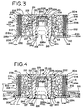
- a thin wall segment at a lower end portion 120a of the cylindrical inner side wall 120 projects downwardly below the underside of the annular base 206 and is adapted to be crimp-formed over and radially outwardly (Arrows C - FIG. 3) toward an adjacent inwardly depressed annular recess 213 on the underside surface of the base around the central opening 207.
- annular step or shoulder 127 is formed at the juncture of a relatively thick upper wall portion of the inner side wall 120 and the relatively thin wall lower end portion 120a.
- the annular step 127 acts as a stop to support the recessed surface portion 213 of the base 206 as the thin wall segment 120a is crimp-formed over radially outwardly (Arrows C - FIG. 3) toward the closing position of FIG. 4 to complete the sealing or closing of the housing 202 around the lower end of the rivet-like central ignition housing member 125.
- An adapter plug 242 preferably formed of metal holds and supports the electrically activated ignition squib 226 and the plug is seated in place to close the lower end of the ignition chamber 224 after the cup 229 of ignition enhancing material 228 has first been inserted.
- An "O" ring 243 may be provided to seal between the body of the adapter plug 242 and the inside surface of the inner side wall 120 of the rivet-like housing member 125, and then the adapter body may be press-fitted into place as shown.
- the adapter 242 may also be secured to the base wall 206 by an annular weld 244.
- An annular weld 246 may be located between the inner side wall portion 120a and the base wall 206 to provide a hermetic seal.
- the outer side wall 212 is formed with a narrow, radially outwardly extending end flange or lip 212a secured to an outer edge portion 206a of the base 206 by a weld 215 (FIG. 4) to provide a hermetic seal.
- a radially extending, annular mounting flange 245 having an inner cylindrical collar 245a is press fitted or otherwise attached to the outer side wall 212 above the flange 212a.
- the use of cold forming operation in crimping over the lower end portion 120a of the stepped inner side wall 120 against the recess edge portion 213 around the central opening 207 of the base 206 and the annular weld 215 (FIG. 4) of an outer edge 206a of the base to the end flange or lip 212a the cylindrical outer side wall 212 greatly facilitates the rapid assembly of the air bag inflator 200 and allows the use of relatively lower cost sheet material such as aluminum or steel instead of more expensive cast or forged structures.
- the crimp-forming operations used in joining the inner side walls 120 to the base wall 206 provides positive compression on the blow-by seals 238 and 240 acting on the filter 234.
- the inflator 300 includes a housing or canister 302 formed of strong, lightweight metal such as aluminum or steel, sheet or plate material having an upper, inverted cup-shaped diffuser cover 304 and a generally circular, annular base or bottom wall 306 having a central opening 307 formed thereon and joined to form a sealed enclosure or housing for containing a quantity of solid, gas generant material 308 in the form of pellets or wafers which rapidly combust to provide a necessary volume of inflation gas for the rapid deployment of an air bag in communication with the inflator 300.
- a housing or canister 302 formed of strong, lightweight metal such as aluminum or steel, sheet or plate material having an upper, inverted cup-shaped diffuser cover 304 and a generally circular, annular base or bottom wall 306 having a central opening 307 formed thereon and joined to form a sealed enclosure or housing for containing a quantity of solid, gas generant material 308 in the form of pellets or wafers which rapidly combust to provide a necessary volume of inflation gas for the rapid deployment of
- the diffuser cover 304 includes an annular top wall 310 and an integrally formed, downwardly depending, cylindrical outer side wall 312.
- the cylindrical outer wall 312 and the annular circular top wall 310 may be formed of sheet aluminum or steel in a spin-forming or deep draw operation, and the outer side wall 312 is provided with a plurality of gas discharge diffuser ports 316 arranged in a ring around the periphery for directing the gas generated in the housing 302 to flow radially outwardly into an air bag (not shown) as indicated by the radially extending arrows A.
- the annular top wall 310 is formed with a circular opening 309 at the center in coaxial alignment with the central opening 307 in the annular base 306.
- the top wall 310 is formed with an annular, downwardly depressed shoulder 311 at a level below the upper surface of an outer portion of the top wall extending radially outwardly thereof and immediately encircling the central opening 309.
- the inflator 300 also includes a centrally disposed, cylindrical inner side wall 120 in coaxial alignment with the outer side wall 312.
- a rivet-like ignition housing member 125 (FIG. 11) fabricated of metal in a forging, deep drawing, or stamping operation includes a circular upper end wall 123 integrally joining the depending inner side wall 120 and closing off the upper end of a central ignition chamber 324 provided in the housing 302.
- the circular upper end wall 123 extends radially outwardly of the central opening 309 a short distance and is sealed with the shoulder surface 311 of the top wall 310 by an annular weld 322, a hermetic seal ring, gasket, or other sealing and joining method.
- the outer upper surfaces of the top wall 310 and the upper end wall 123 of the rivet-like housing member 125 are substantially aligned as shown to provide a flat overall upper surface for the housing 302.
- the ignition chamber 324 contains an electrically activated ignition squib 326 and a charge 328 of an ignition-enhancing material contained within an igniter cup 329 positioned in the upper end portion of the chamber.
- the ignition squib 326 is electrically activated and includes a pair of downwardly depending electrical terminals 326a adapted for connection to an external electrical activation system of a motor vehicle.
- the inner side wall 120 is formed with a plurality of ignition ports 130 in direct communication between the ignition chamber 324 and an outer, surrounding, annular, combination combustion and filter-containing chamber 332.
- the gas generant material 308 is arranged in an annular mass in an inner portion of the chamber 332 and is encircled by an outer, annular gas filter 334 mounted adjacent the inside surface of the outer side wall 312.
- the ignition chamber wall ports 130 direct hot combustion products from the ignition squib 326 and the ignition enhancing material 328 into the annulus of gas generant pellets 308 as indicated by the arrows B.
- annular gas filters 334 may be utilized; and in general, the filter includes a large area, cylindrically-shaped, inner face or inlet side, for receiving hot combustion products generated in the housing 302 and an outer surface in facing confrontation with the diffuser discharge ports 316 in the ported outer side wall 312.
- the diffuser wall ports 316 are sealed off against the entry of outside contaminants during the life of the inflator 300 before activation by means of a thin adhesively secured, sealing tape 336, which tape is readily ruptured by gas pressure when activation of the inflator 300 to fill an associated air bag takes place.
- Upper and lower annular end surfaces of the filter 334 are sealed against the underside of the top wall 310 and the upper surface of the base wall 306, respectively, by a pair of resilient, annular, sealing ring gaskets 338 and 340 in order to prevent blow-by of the hot gases around the upper and lower annular end faces of the gas filter 334.
- the sealing rings 338 and 340 ensure good filtering action by containing the gas flow within the available flow cross-section of the gas filter 334 until the gas exits the outer face to reach the diffuser wall gas discharge ports 316.
- a thin wall segment at a lower end portion 120a of the cylindrical inner side wall 120 projects downwardly below the underside of the annular base 306 and is adapted to be crimp-formed over and radially outwardly (Arrows C - FIG. 5) toward an adjacent inwardly depressed annular recess 313 on the underside surface of the base around the central opening 307.
- annular step or shoulder 127 is formed at the juncture of a relatively thick upper wall portion of the inner side wall 120 and the relatively thin wall lower end portion 120a.
- the annular step 127 acts as a stop to support the recessed surface portion 313 of the base 306 as the thin wall segment 120a is crimp-formed over radially outwardly (Arrows C - FIG. 5) toward the closing position of FIG. 6 to complete the sealing or closing of the housing 302 around the lower end of the rivet-like central ignition housing member 125.
- An adapter plug 342 preferably formed of metal holds and supports the electrically activated ignition squib 326 and the plug is seated in place to close the lower end of the ignition chamber 324 after the cup 329 of ignition enhancing material 328 has first been inserted.
- a seal 343 may be provided to seal between the body of the adapter plug 342 and the inside surface of the inner side wall 120 of the rivet-like housing member 125, and then the adapter body may be press-fitted into place as shown.
- the adapter 342 may also be secured to the base wall 306 by an annular weld 344.
- An annular weld 346, a seal ring or a gasket, may be located between or to the inner side wall portion 120a and the base wall 306 to provide a hermetic seal.
- An optional annular weld 345 (FIG. 6) between the thin wall segment 120a and a lower end portion of an adapter plug 342 may also be provided.
- the outer side wall 312 is formed with a narrow, radially outwardly extending end flange or lip 312a and the base 306 is provided with an upwardly projecting flange 306a (FIG. 5) adapted to be crimp-formed over (Arrows D) to a radially inwardly directed position (FIG. 6) to engage an upper surface of the wall flange or lip 312a to provide a structural closure.
- a separate seal 346 or seal ring 340 may be wholly or partially trapped by this joint to form a hermetic seal.
- a radially extending, annular mounting flange 345 having an inner cylindrical collar 345a is press fitted or otherwise attached to the outer side wall 312 above the flange 312a.
- the use of cold forming operation in crimping over the lower end portion 120a of the stepped inner side wall 120 against the recess edge portion 313 around the central opening 307 of the base 306 and the crimped-over upwardly and radially inwardly extending edge 306a of the base engaging the end flange or lip 312a of the cylindrical outer side wall 312 greatly facilitates the rapid assembly of the air bag inflator 300 and allows the use of relatively lower cost sheet material of aluminum or steel instead of more expensive cast or forged structures.
- the crimp-forming operations used in joining the inner and outer side walls 120 and 312, respectively, to the base wall 306, also provides positive compression on the blow-by seals 338 and 340 acting on the filter 334.
- the inflator 400 includes a housing or canister 402 formed of strong, lightweight metal such as aluminum or steel, sheet or plate material having an upper, inverted cup-shaped diffuser cover 404 and a generally circular, annular base or bottom wall 406 having a central opening 407 formed thereon and joined to form a sealed enclosure or housing for containing a quantity of solid, gas generant material 408 in the form of pellets or wafers which rapidly combust to provide a necessary volume of inflation gas for the rapid deployment of an air bag in communication with the inflator 400.
- a housing or canister 402 formed of strong, lightweight metal such as aluminum or steel, sheet or plate material having an upper, inverted cup-shaped diffuser cover 404 and a generally circular, annular base or bottom wall 406 having a central opening 407 formed thereon and joined to form a sealed enclosure or housing for containing a quantity of solid, gas generant material 408 in the form of pellets or wafers which rapidly combust to provide a necessary volume of inflation gas for the rapid deployment of
- the diffuser cover 404 includes an annular top wall 410 and an integrally formed, downwardly depending, cylindrical outer side wall 412.
- the cylindrical outer wall 412 and the annular circular top wall 410 may be formed of sheet aluminum or steel in a spin-forming or deep draw operation, and the outer side wall 412 is provided with a plurality of gas discharge diffuser ports 416 arranged in a ring around the periphery for directing the gas generated in the housing 402 to flow radially outwardly into an air bag (not shown) as indicated by the radially extending arrows A.
- the annular top wall 410 is formed with a circular opening 409 at the center in coaxial alignment with the central opening 407 in the annular base 406.
- the top wall 410 is formed with an annular, downwardly depressed shoulder 411 at a level below the upper surface of an outer portion of the top wall extending radially outwardly thereof and immediately encircling the central opening 409.
- the inflator 400 also includes a centrally disposed, cylindrical inner side wall 120 in coaxial alignment with the outer side wall 412.
- a rivet-like ignition housing member 125 (FIG. 11) fabricated of metal in a forging, deep drawing, or stamping operation includes a circular upper end wall 123 integrally joining the depending inner side wall 120 and closing off the upper end of a central ignition chamber 424 provided in the housing 402.
- the circular upper end wall 123 extends radially outwardly of the central opening 409 a short distance and is sealed with the shoulder surface 411 of the top wall 410 by an annular weld 422, a hermetic seal ring, gasket, or other sealing and joining method.
- the outer upper surfaces of the top wall 410 and the upper end wall 123 of the rivet-like housing member 125 are substantially aligned as shown to provide a flat overall upper surface for the housing 402.
- the ignition chamber 424 contains an electrically activated ignition squib 426 and a charge 428 of an ignition-enhancing material contained within an igniter cup 429 positioned in the upper end portion of the chamber.
- the ignition squib 426 is electrically activated and includes a pair of downwardly depending electrical terminals 426a adapted for connection to an external electrical activation system of a motor vehicle.
- the inner side wall 120 is formed with a plurality of ignition ports 130 in direct communication between the ignition chamber 424 and an outer, surrounding, annular, combination combustion and filter-containing chamber 432.
- the gas generant material 408 is arranged in an annular mass in an inner portion of the chamber 432 and is encircled by an outer, annular gas filter 434 mounted adjacent the inside surface of the outer side wall 412.
- the ignition chamber wall ports 130 direct hot combustion products from the ignition squib 426 and the ignition enhancing material 428 into the annulus of gas generant pellets 408 as indicated by the arrows B.
- annular gas filters 434 may be utilized; and in general, the filter includes a large area, cylindrically-shaped, inner face or inlet side, for receiving hot combustion products generated in the housing 402 and an outer surface in facing confrontation with the diffuser discharge ports 416 in the ported outer side wall 412.
- the diffuser wall ports 416 are sealed off against the entry of outside contaminants during the life of the inflator 400 before activation by means of a thin adhesively secured, sealing tape 436, which tape is readily ruptured by gas pressure when activation of the inflator 400 to fill an associated air bag takes place.
- Upper and lower annular end surfaces of the filter 434 are sealed against the underside of the top wall 410 and the upper surface of the base wall 406, respectively, by a pair of resilient, annular, sealing ring gaskets 438 and 440 in order to prevent blow-by of the hot gases around the upper and lower annular end faces of the gas filter 434.
- the sealing rings 438 and 440 ensure good filtering action by containing the gas flow within the available flow cross-section of the gas filter 434 until the gas exits the outer face to reach the diffuser wall gas discharge ports 416.
- a thin wall segment at a lower end portion 120a of the cylindrical inner side wall 120 projects downwardly below the underside of the annular base 406 and is adapted to be crimp-formed over and radially outwardly (Arrows C - FIG. 7) toward an adjacent inwardly depressed annular recess 413 on the underside surface of the base around the central opening 407.
- annular step or shoulder 127 is formed at the juncture of a relatively thick upper wall portion of the inner side wall 120 and the relatively thin wall lower end portion 120a.
- the annular step 127 acts as a stop to support the recessed surface portion 413 of the base 406 as the thin wall segment 120a is crimp-formed over radially outwardly (Arrows C - FIG. 7) toward the closing position of FIG. 8 to complete the sealing or closing of the housing 402 around the lower end of the rivet-like central ignition housing member 125.
- An adapter plug 442 preferably formed of metal holds and supports the electrically activated ignition squib 426 and the plug is seated in place to close the lower end of the ignition chamber 424 after the cup 429 of ignition enhancing material 428 has first been inserted.
- An "O" ring 443 may be provided to seal between the body of the adapter plug 442 and the inside surface of the inner side wall 120 of the rivet-like housing member 125, and then the adapter body may be press-fitted into place as shown.
- the adapter 442 may also be secured to the base wall 406 by an annular weld 444.
- An annular weld 446, a seal ring or a gasket may be located between the inner side wall portion 120a and the base wall 406 to provide a hermetic seal.
- the outer side wall 412 is formed with a lower end portion 412a extending below the base 406 (FIG. 7) and this lower end portion is crimped over (Arrows E) to extend downwardly, radially inwardly and then upwardly (FIG. 8) forming an annular groove 412b for receiving an outer edge portion 406a of the base wall 406 which is stamp formed with a matching groove profile to interfit with the crimp-formed outer side wall lower end portion 412a.
- the interfitting grooved portions 412a and 406a of the outer side wall 412 and base 406 provide an extremely strong structure at the lower outer periphery of the housing 402.
- a radially extending, annular mounting flange 445 having an inner cylindrical collar 445a is press fitted or otherwise attached to the outer side wall 412 above the flange 412a.
- the inflator 500 includes a housing or canister 502 formed of strong, lightweight metal such as aluminum or steel, sheet or plate material having an upper, inverted cup-shaped diffuser cover 504 and a generally circular, annular base or bottom wall 506 having a central opening 507 formed thereon and joined to form a sealed enclosure or housing for containing a quantity of solid, gas generant material 508 in the form of pellets or wafers which rapidly combust to provide a necessary volume of inflation gas for the rapid deployment of an air bag in communication with the inflator 500.
- a housing or canister 502 formed of strong, lightweight metal such as aluminum or steel, sheet or plate material having an upper, inverted cup-shaped diffuser cover 504 and a generally circular, annular base or bottom wall 506 having a central opening 507 formed thereon and joined to form a sealed enclosure or housing for containing a quantity of solid, gas generant material 508 in the form of pellets or wafers which rapidly combust to provide a necessary volume of inflation gas for the rapid deployment of
- the diffuser cover 504 includes an annular top wall 510 and an integrally formed, downwardly depending, cylindrical outer side wall 512.
- the cylindrical outer wall 512 and the annular circular top wall 510 may be formed of sheet aluminum or steel in a spin-forming or deep draw operation, and the outer side wall 512 is provided with a plurality of gas discharge diffuser ports 516 arranged in a ring around the periphery for directing the gas generated in the housing 502 to flow radially outwardly into an air bag (not shown) as indicated by the radially extending arrows A.
- the annular top wall 510 is formed with a circular opening 509 at the center in coaxial alignment with the central opening 507 in the annular base 506.
- the top wall 510 is formed with an annular, downwardly depressed shoulder 511 at a level below the upper surface of an outer portion of the top wall extending radially outwardly thereof and immediately encircling the central opening 509.
- the inflator 500 also includes a centrally disposed, cylindrical inner side wall 120 in coaxial alignment with the outer side wall 512.
- a rivet-like ignition housing member 125 (FIG. 11) fabricated of metal in a forging, deep drawing, or stamping operation includes a circular upper end wall 123 integrally joining the depending inner side wall 120 and closing off the upper end of a central ignition chamber 524 provided in the housing 502.
- the circular upper end wall 123 extends radially outwardly of the central opening 509 a short distance and is sealed with the shoulder surface 511 of the top wall 510 by an annular weld 522, a hermetic seal ring, gasket, or other sealing and joining method.
- the outer upper surfaces of the top wall 510 and the upper end wall 123 of the rivet-like housing member 125 are substantially aligned as shown to provide a flat overall upper surface for the housing 502.
- the ignition chamber 524 contains an electrically activated ignition squib 526 and a charge 528 of an ignition-enhancing material contained within an igniter cup 529 positioned in the upper end portion of the chamber.
- the ignition squib 526 is electrically activated and includes a pair of downwardly depending electrical terminals 526a adapted for connection to an external electrical activation system of a motor vehicle.
- the inner side wall 120 is formed with a plurality of ignition ports 130 in direct communication between the ignition chamber 524 and an outer, surrounding, annular, combination combustion and filter-containing chamber 532.
- the gas generant material 508 is arranged in an annular mass in an inner portion of the chamber 532 and is encircled by an outer, annular gas filter 534 mounted adjacent the inside surface of the outer side wall 512.
- the ignition chamber wall ports 130 direct hot combustion products from the ignition squib 526 and the ignition enhancing material 528 into the annulus of gas generant pellets 508 as indicated by the arrows B.
- annular gas filters 534 may be utilized; and in general, the filter includes a large area, cylindrically-shaped, inner face or inlet side, for receiving hot combustion products generated in the housing 502 and an outer surface in facing confrontation with the diffuser discharge ports 516 in the ported outer side wall 512.
- the diffuser wall ports 516 are sealed off against the entry of outside contaminants during the life of the inflator 500 before activation by means of a thin adhesively secured, sealing tape 536, which tape is readily ruptured by gas pressure when activation of the inflator 500 to fill an associated air bag takes place.
- Upper and lower annular end surfaces of the filter 534 are sealed against the underside of the top wall 510 and the upper surface of the base wall 506, respectively, by a pair of resilient, annular, sealing ring gaskets 538 and 540 in order to prevent blow-by of the hot gases around the upper and lower annular end faces of the gas filter 534.
- the sealing rings 538 and 540 ensure good filtering action by containing the gas flow within the available flow cross-section of the gas filter 534 until the gas exits the outer face to reach the diffuser wall gas discharge ports 516.
- Sealing ring 540 or an optional seal ring 546 provide a hermetic seal between the base 506 and outer side wall 512a.
- a thin wall segment at a lower end portion 120a of the cylindrical inner side wall 120 initially projects downwardly below the underside of the annular base 506 and is adapted to be crimp-formed over and radially outwardly toward an adjacent annular surface 513 on the underside surface of the base around the central opening 507.
- annular step or shoulder 127 is formed at the juncture of a relatively thick upper wall portion of the inner side wall 120 and the relatively thin wall lower end portion 120a.
- the annular step 127 acts as a stop to support the central portion 513 of the base 506 around the opening 507 as the thin wall segment 120a is crimp-formed over radially outwardly as described in several embodiments heretofore toward the closed position as shown, to complete the sealing or closing of the housing 502 around the lower end of the rivet-like central ignition housing member 125.
- An adapter plug 542 preferably formed of metal holds and supports the electrically activated ignition squib 526 and the plug is seated in place to close the lower end of the ignition chamber 524 after the cup 529 of ignition enhancing material 228 has first been inserted.
- An "O" ring 543 may be provided to seal between the body of the adapter plug 542 and the inside surface of the inner side wall 120 of the rivet-like housing member 125, and then the adapter body may be press-fitted into place as shown.
- the adapter plug 542 may also be secured to the base wall 506 by an annular weld 544.
- An annular weld 546, seal ring or a gasket may be located between the inner side wall portion 120a and the base wall 506 to provide a hermetic seal.
- the outer side wall 512 is formed with a crimp-formed flange 512a turned radially inwardly and then extended upwardly to terminate in an end face 506b bearing against the underside of an upwardly deformed or offset, marginal outer edge portion 506a of the base 506 to provide a structural closure.
- An outer peripheral edge 506b of the base 506 bears against and supports an inside surface of the outer side wall 512 as the flange portion 512a is formed. This arrangement results in an extremely strong crimp-formed joint around the lower outer peripheral corner of the housing 502 that is well able to withstand high internal pressures.
- a radially extending, annular mounting flange 545 having an inner cylindrical collar 545a is fitted onto the outer side wall 512 and the collar has a radially inwardly and upwardly extending, pre-formed flange 545b which fits around the underside of the outer side wall flange 512a as shown.
- the inflator 600 includes a housing or canister 602 formed of strong, lightweight metal such as aluminum or steel, sheet or plate material having an upper, inverted cup-shaped diffuser cover 604 and a generally circular, annular base or bottom wall 606 having a central opening 607 formed thereon and joined to form a sealed enclosure or housing for containing a quantity of solid, gas generant material 608 in the form of pellets or wafers which rapidly combust to provide a necessary volume of inflation gas for the rapid deployment of an air bag in communication with the inflator 600.
- a housing or canister 602 formed of strong, lightweight metal such as aluminum or steel, sheet or plate material having an upper, inverted cup-shaped diffuser cover 604 and a generally circular, annular base or bottom wall 606 having a central opening 607 formed thereon and joined to form a sealed enclosure or housing for containing a quantity of solid, gas generant material 608 in the form of pellets or wafers which rapidly combust to provide a necessary volume of inflation gas for the rapid deployment of
- the diffuser cover 604 includes an annular top wall 610 and an integrally formed, downwardly depending, cylindrical outer side wall 612.
- the cylindrical outer wall 612 and the annular circular top wall 610 may be formed of sheet aluminum or steel in a spin-forming or deep draw operation, and the outer side wall 612 is provided with a plurality of gas discharge diffuser ports 616 arranged in a ring around the periphery for directing the gas generated in the housing 602 to flow radially outwardly into an air bag (not shown) as indicated by the radially extending arrows A.
- the annular top wall 610 is formed with a circular opening 609 at the center in coaxial alignment with the central opening 607 in the annular base 606.
- the top wall 610 is formed with an annular, downwardly depressed shoulder 611 at a level below the upper surface of an outer portion of the top wall extending radially outwardly thereof and immediately encircling the central opening 609.
- the inflator 600 also includes a centrally disposed, cylindrical inner side wall 120 in coaxial alignment with the outer side wall 612.
- a rivet-like ignition housing member 125 (FIG. 11) fabricated of metal in a forging, deep drawing, or stamping operation includes a circular upper end wall 123 integrally joining the depending inner side wall 120 and closing off the upper end of a central ignition chamber 624 provided in the housing 602.
- the circular upper end wall 123 extends radially outwardly of the central opening 609 a short distance and is sealed with the shoulder surface 611 of the top wall 610 by an annular weld 622, a hermetic seal ring, gasket, or other sealing and joining method.
- the outer upper surfaces of the top wall 610 and the upper end wall 123 of the rivet-like housing member 125 are substantially aligned as shown to provide a flat overall upper surface for the housing 602.
- the ignition chamber 624 contains an electrically activated ignition squib 626 and a charge 628 of an ignition-enhancing material contained within an igniter cup 629 positioned in the upper end portion of the chamber.
- the ignition squib 626 is electrically activated and includes a pair of downwardly depending electrical terminals 626a adapted for connection to an external electrical activation system of a motor vehicle.
- the inner side wall 120 is formed with a plurality of ignition ports 130 in direct communication between the ignition chamber 624 and an outer, surrounding, annular, combination combustion and filter-containing chamber 632.
- the gas generant material 608 is arranged in an annular mass in an inner portion of the chamber 632 and is encircled by an outer, annular gas filter 634 mounted adjacent the inside surface of the outer side wall 612.
- the ignition chamber wall ports 130 direct hot combustion products from the ignition squib 626 and the ignition enhancing material 628 into the annulus of gas generant pellets 608 as indicated by the arrows B.
- annular gas filters 634 may be utilized; and in general, the filter includes a large area, cylindrically-shaped, inner face or inlet side, for receiving hot combustion products generated in the housing 602 and an outer surface in facing confrontation with the diffuser discharge ports 616 in the ported outer side wall 612.
- the diffuser wall ports 616 are sealed off against the entry of outside contaminants during the life of the inflator 600 before activation by means of a thin adhesively secured, sealing tape 636, which tape is readily ruptured by gas pressure when activation of the inflator 600 to fill an associated air bag takes place.
- Upper and lower annular end surfaces of the filter 634 are sealed against the underside of the top wall 610 and the upper surface of the base wall 606, respectively, by a pair of resilient, annular, sealing ring gaskets 638 and 640 in order to prevent blow-by of the hot gases around the upper and lower annular end faces of the gas filter 634.
- the sealing rings 638 and 640 ensure good filtering action by containing the gas flow within the available flow cross-section of the gas filter 634 until the gas exits the outer face to reach the diffuser wall gas discharge ports 616.
- a thin wall segment at a lower end portion 120a of the cylindrical inner side wall 120 initially projects downwardly below the underside of the annular base 606 and is adapted to be crimp-formed over and radially. outwardly as previously described toward an adjacent annular surface 613 on the underside surface of the base 606 around the central opening 607.
- annular step or shoulder 127 is formed at the juncture of a relatively thick upper wall portion of the inner side wall 120 and the relatively thin wall lower end portion 120a.
- the annular step 127 acts as a stop to support the surface portion 613 of the base 606 as the thin wall segment 120a is crimp-formed over radially outwardly toward the closing position to complete the sealing or closing of the housing 602 around the lower end of the rivet-like central ignition housing member 125.
- An adapter plug 642 preferably formed of metal holds and supports the electrically activated ignition squib 626 and the plug is seated in place to close the lower end of the ignition chamber 624 after the cup 629 of ignition enhancing material 628 has first been inserted.
- An "O" ring 643 may be provided to seal between the body of the adapter plug 642 and the inside surface of the inner side wall 120 of the rivet-like housing member 125, and then the adapter body may be press-fitted into place as shown.
- the adapter 642 may also be secured to the base wall 606 by an annular weld 646.
- An annular weld 644 may be provided to seal the wall 120a and the base 606 inside the opening 613.
- An annular weld 646, a seal ring or a gasket may be located between the inner side wall portion 120a and the base wall 606 to provide a hermetic seal.
- the outer side wall 612 is formed with a narrow, radially inwardly turned and upwardly extending end flange or lip 612a for securing a short, downturned lip 606b on an outer edge portion 606a of the base 606 to provide a structural closure.
- An upper end 612b of the upturned lip 612a bears against the underside of the base 106 inwardly of the outer downturned lip 606b which is sandwiched between the inner surface of the outer side wall 612 and upstanding lip 612a to provide an extremely strong joint and tight seal.
- a seal 640 may be provided to establish hermetic sealing of the joint area.
- a radially extending, annular mounting flange 645 having an inner cylindrical collar 645a is fitted onto the outer side wall 612 and a lower end portion 645b is turned under the inwardly and upwardly turned lower end portion 612a of the outer side wall 612 to provide further strengthening.
- the inflator 700 includes a housing or canister 702 formed of strong, lightweight metal such as aluminum or steel, sheet or plate material having an upper, inverted cup-shaped diffuser cover 704 and a generally circular, annular base or bottom wall 706 having a central opening 707 formed thereon and joined to form a sealed enclosure or housing for containing a quantity of solid, gas generant material 708 in the form of pellets or wafers which rapidly combust to provide a necessary volume of inflation gas for the rapid deployment of an air bag in communication with the inflator 700.
- a housing or canister 702 formed of strong, lightweight metal such as aluminum or steel, sheet or plate material having an upper, inverted cup-shaped diffuser cover 704 and a generally circular, annular base or bottom wall 706 having a central opening 707 formed thereon and joined to form a sealed enclosure or housing for containing a quantity of solid, gas generant material 708 in the form of pellets or wafers which rapidly combust to provide a necessary volume of inflation gas for the rapid deployment of
- the diffuser cover 704 includes an annular top wall 710 and an integrally formed, downwardly depending, cylindrical outer side wall 712.
- the cylindrical outer wall 712 and the annular circular top wall 710 may be formed of sheet aluminum or steel in a spin-forming or deep draw operation, and the outer side wall 712 is provided with a plurality of gas discharge diffuser ports 716 arranged in a ring around the periphery for directing the gas generated in the housing 702 to flow radially outwardly into an air bag (not shown) as indicated by the radially extending arrows A.
- the annular top wall 710 is formed with a circular opening 709 at the center in coaxial alignment with the central opening 707 in the annular base 706.
- the top wall 710 is formed with an annular, downwardly depressed shoulder 711 at a level below the upper surface of an outer portion of the top wall extending radially outwardly thereof and immediately encircling the central opening 709.
- the inflator 700 also includes a centrally disposed, cylindrical inner side wall 120 in coaxial alignment with the outer side wall 712.
- a rivet-like ignition housing member 125 (FIG. 11) fabricated of metal in a forging, deep drawing, or stamping operation includes a circular upper end wall 123 integrally joining the depending inner side wall 120 and closing off the upper end of a central ignition chamber 724 provided in the housing 702.
- the circular upper end wall 123 extends radially outwardly of the central opening 709 a short distance and is sealed with the shoulder surface 711 of the top wall 710 by an annular weld 722, a hermetic seal ring, gasket, or other sealing and joining method.
- the outer upper surfaces of the top wall 710 and the upper end wall 123 of the rivet-like housing member 125 are substantially aligned as shown to provide a flat overall upper surface for the housing 702.
- the ignition chamber 724 contains an electrically activated ignition squib 726 and a charge 728 of an ignition-enhancing material contained within an igniter cup 729 positioned in the upper end portion of the chamber.
- the ignition squib 726 is electrically activated and includes a pair of downwardly depending electrical terminals 726a adapted for connection to an external electrical activation system of a motor vehicle.
- the inner side wall 120 is formed with a plurality of ignition ports 130 in direct communication between the ignition chamber 724 and an outer, surrounding, annular, combination combustion and filter-containing chamber 732.
- the gas generant material 708 is arranged in an annular mass in an inner portion of the chamber 732 and is encircled by an outer, annular gas filter 734 mounted adjacent the inside surface of the outer side wall 712.
- the ignition chamber wall ports 130 direct hot combustion products from the ignition squib 726 and the ignition enhancing material 728 into the annulus of gas generant pellets 708 as indicated by the arrows B.
- annular gas filters 734 may be utilized; and in general, the filter includes a large area, cylindrically-shaped, inner face or inlet side, for receiving hot combustion products generated in the housing 702 and an outer surface in facing confrontation with the diffuser discharge ports 716 in the ported outer side wall 712.
- the diffuser wall ports 716 are sealed off against the entry of outside contaminants during the life of the inflator 700 before activation by means of a thin adhesively secured, sealing tape 736, which tape is readily ruptured by gas pressure when activation of the inflator 700 to fill an associated air bag takes place.
- Upper and lower annular end surfaces of the filter 734 are sealed against the underside of the top wall 710 and the upper surface of the base wall 706, respectively, by a pair of resilient, annular, sealing ring gaskets 738 and 740 in order to prevent blow-by of the hot gases around the upper and lower annular end faces of the gas filter 734.
- the sealing rings 738 and 740 ensure good filtering action by containing the gas flow within the available flow cross-section of the gas filter 734 until the gas exits the outer face to reach the diffuser wall gas discharge ports 716.
- a thin wall segment at a lower end portion 120a of the cylindrical inner side wall 120 initially projects downwardly below the underside of the annular base 706 and is adapted to be crimp-formed over and radially outwardly toward an adjacent annular surface 713 on the underside surface of the base around the central opening 707.
- annular step or shoulder 127 is formed at the juncture of a relatively thick upper wall portion of the inner side wall 120 and the relatively thin wall lower end portion 120a.
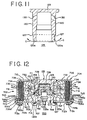
- the annular step 127 acts as a stop to support the surface portion 713 of the base 706 as the thin wall segment 120a is crimp-formed over radially outwardly and upwardly toward the closing position of FIG. 12 against an annular sheet 747 of resilient sealing material to complete the sealing or closing of the housing 702 around the lower end of the rivet-like central ignition housing member 125 and between an outer side wall portion 712b of the outer side wall 710 and the base 706.
- An adapter plug 742 preferably formed of metal holds and supports the electrically activated ignition squib 726 and the plug is seated in place to close the lower end of the ignition chamber 724 after the cup 729 of ignition enhancing material 728 has first been inserted.
- the adapter plug 742 has a body surface closely adjacent the inside surface of the inner side wall 120 of the rivet-like housing member 125, and may be press-fitted into place as shown.
- the adapter 742 may also be secured by an annular weld 744 to the inner surface of the inner surface of the inner side wall 120 to provide a hermetic seal.
- a pre-formed lower end portion 712a of the outer side wall 712 is formed to provide a curved stop portion 749 sloping radially outwardly and downwardly and thereafter during assembly, the outer side wall 712 is crimp-formed radially inwardly establishing the flange portion 712b below the base 706.
- the outwardly extending stepped portion of the lower outer wall portion 712a forms an internal annular shoulder or stop surface 749 for supportively engaging an upper end 706b of an upturned lip 706b provided at the outer edge 706a of the base 706. This supportive engagement prevents upward movement of the base 706 during the final assembly crimp-forming operation directing the lower end flange 712b radially inwardly and upwardly toward the sealing sheet 747 and the base 706.
- a radially extending, annular mounting flange 745 having an inner cylindrical collar 745a is fitted onto the outer side wall 712.
- the collar 745a is deformed radially inwardly to match the shape of the outer side wall 712 and the lower end portion 712a to provide further strength for the lower outer edge of the housing 702.
Landscapes
- Physics & Mathematics (AREA)
- Fluid Mechanics (AREA)
- Engineering & Computer Science (AREA)
- Mechanical Engineering (AREA)
- Air Bags (AREA)
Claims (23)
- Logement (102) de gonfleur de coussin airbag (100), le logement étant formé à partir de l'emboutissage d'une tôle métallique et comportant: un socle annulaire (106) ayant une ouverture centrale (107), un capot (104) retenant l'équipement pyrotechnique générateur de gaz (108) y compris une paroi annulaire supérieure (110) à distance dudit socle (106) comportant une ouverture centrale (109) en alignement coaxial avec ladite ouverture centrale (107) dudit socle (106) et une paroi extérieure latérale cylindrique à orifice (112) formée intégrale autour d'un pourtour de ladite paroi supérieure (110) qui en est allongée vers le bas, et un rivet creux contenant l'allumeur (125) ou un dispositif de fixation comportant une paroi d'extrémité supérieure (123) se refermant sur ladite ouverture centrale (109) de ladite paroi supérieure (110) et ayant une paroi latérale tubulaire à orifice (123), formée intégrale avec ladite paroi supérieure extrême (123) qui s'étend vers le bas au travers desdites ouvertures centrales (107,109) dudit socle (106) et de ladite paroi supérieure (110), caractérisé en ce que ladite paroi latérale tubulaire (120) comporte une portion inférieure extrême (120a) d'épaisseur de paroi réduite sous une surface supérieure dudit socle (106) autour de ladite ouverture centrale (107) formant un épaulement annulaire extérieur (127) en prise de support avec ledit socle (106), ladite portion inférieure extrême (120a) étant déformée en sens radial vers l'extérieur pour venir en prise avec un côté inférieur dudit socle (106) et en ce que ladite paroi latérale extérieure (112) comporte une portion de bord inférieur (112a) retenue par des moyens de retenue avec une portion dudit socle (106) à l'extérieur de ladite ouverture centrale (107).
- Le logement à la revendication 1, selon lequel ledit rivet (129) comporte une bride d'extrémité supérieure qui s'étend en sens radial vers l'extérieur à partir de ladite paroi latérale tubulaire (120) ayant un côté inférieur situé face à la portion de surface supérieure de ladite paroi supérieure (110) autour de ladite ouverture centrale (109).
- Le logement à la revendication 2, selon lequel ladite portion de surface supérieure de ladite paroi supérieure (110) autour de ladite ouverture centrale (109) est comprimée vers le bas à partir d'une portion de surface supérieure en sens radial extérieur de ladite paroi supérieure (110) pour admettre ladite bride supérieure extrême dudit rivet (125).
- Le logement à l'une ou l'autre des revendications précédentes, selon lequel ledit socle annulaire (106) prévoit une portion intérieure radiale autour de ladite ouverture centrale (107) comprimée vers le haut depuis une portion extérieure inférieure de surface en sens radial extérieur pour en admettre la portion d'épaisseur réduite d'extrémité inférieure de paroi (120a) de ladite paroi latérale tubulaire (120) lors de sa déformation extérieure radiale de manière à faire face à ladite portion comprimée intérieure dudit socle (106).
- Le logement à l'une ou l'autre des revendications précédentes comportant: des garnitures annulaires hermétiques entre les extrémités supérieure et inférieure dudit rivet (125) autour desdites ouvertures centrales (107, 109) dudit socle annulaire (106) et de ladite paroi supérieure (110).
- Le logement à l'une ou l'autre des revendications précédentes, y compris une bride d'assemblage (106b) dudit logement en extension radiale extérieure depuis ladite paroi latérale extérieure (112).
- Le logement à l'une ou l'autre des revendications précédentes, selon lequel ledit moyen de fixation prévoit la soudure (115).
- Le logement à la revendication 7 selon lequel ledit moyen de fixation prévoit la soudure au laser.
- Le logement à l'une ou l'autre des revendications précédentes, selon lequel ledit moyen de fixation prévoit une portion extérieure (106a) dudit socle (106) en saillie vers le haut pour venir en prise avec la surface extérieure d'une portion de bord inférieur de ladite paroi latérale extérieure (112).
- Le logement à la revendication 9 selon lequel ladite portion en saillie extérieure vers le haut (106a) dudit socle (106) est raccordée intégrale avec une bride annulaire d'assemblage (106b) en saillie radiale extérieure depuis ladite paroi extérieure (112).
- Le logement à la revendication 10 selon lequel ledit socle annulaire d'assemblage (106b) est formé à partir d'une portion de bord périphérique (106c) à un bord extérieur qui lui est généralement situé normal et concentrique avec ladite portion extérieure en saillie vers le haut (106a).
- Le logement à l'une ou l'autre des revendications 1 à 8 selon lequel ledit moyen de fixation prévoit une bride inférieure de bord (212a) sur ladite paroi latérale extérieure (112) déformée de façon à s'étendre en sens radial extérieur qui vient en prise de soutien avec une surface supérieure de portion de bord extérieur dudit socle (206).
- Le logement à la revendication 12, y compris une bride d'assemblage (245) située à un niveau au dessus de la bride inférieure de bord (212a) de ladite paroi latérale extérieure (212) qui prévoit un collier intérieur intégral (245a) raccordé autour de ladite paroi latérale extérieur (212) en extension vers le haut par rapport à ladite bride inférieure de bord (212a).
- Le logement à la revendication 12, dont un élément de ladite portion extérieure de bord dudit socle (306) comporte une bride dirigée en sens montant et en sens radial vers l'intérieur (306a) qui vient en prise avec ladite bride d'extrémité inférieure (312a) de ladite latérale extérieure (312).
- Le logement à la revendication 14, dont ladite bride d'extrémité inférieure (312a) de ladite paroi extérieure (312) est prise en sandwich entre des segments supérieur et inférieur de ladite portion de bord dudit socle et comporte un bord périphérique extérieur recouvert par un segment dirigé montant de ladite portion extérieure de bord dudit socle (306).
- Le logement à l'une ou l'autre des revendications 1 à 8 selon lequel ledit moyen de fixation comporte une portion de bord inférieur de ladite paroi latérale extérieure (412) formée pour assurer une bride d'extrémité dirigée radiale vers l'intérieur (412a) qui s'engage avec un côte inférieur dudit socle (406) extérieurement depuis ladite ouverture centrale (407).
- Le logement à la revendication 16 selon lequel ledit socle (406) comporte une rainure annulaire en extension montante formée dans une surface inférieure éloignée intérieurement par rapport à un bord périphérique extérieur et ladite bride (412a) d'extrémité dirigée en sens radial intérieur de ladite paroi latérale extérieure (412) s'étend dans et se termine dans ladite rainure.
- Le logement à la revendication 16 ou 17 selon lequel ledit socle prévoit une surface annulaire inférieure en pente montante et radiale extérieure de ladite rainure qui se situe face à une surface supérieure (412b) de ladite bride d'extrémité dirigée radiale intérieure (412a) de ladite paroi latérale extérieure (412).
- Le logement à l'une ou l'autre des revendications 16 à 18 selon lequel ladite bride d'extrémité (412a) de ladite paroi latérale extérieure (412) s'étend vers le haut ainsi que vers l'intérieur.
- Le logement à la revendication 19 selon lequel ladite portion d'extrémité inférieure (612a) de ladite paroi latérale extérieure prévoit un congé annulaire qui s'ouvre sur le haut à proximité d'une surface intérieure de ladite paroi latérale extérieure (612).
- Le logement à la revendication 20, selon lequel ledit socle (606) prévoit une bride annulaire dirigée vers le bas (606b) autour d'une périphérie extérieure qui s'étend vers le bas dans ledit congé annulaire et vient en prise avec une surface intérieure de ladite paroi latérale extérieure (612).
- Le logement à l'une ou l'autre des revendications 1 à 8 selon lequel ledit moyen de fixation prévoit une portion d'extrémité inférieure (712a) de ladite paroi latérale extérieure (712) déformée en sens radial extérieur et intérieur assurant une rainure intérieure en saillie radiale extérieure par rapport à une portion supérieure de surface intérieure de ladite paroi latérale extérieure (712) formant une surface annulaire de butée dirigée vers le bas (749) qui vient en prise avec une portion de bord extérieur périphérique (706a) dudit socle (705) dont un côté inférieur (747) vient en prise avec ladite portion d'extrémité inférieure (712a) de ladite paroi latérale extérieure (712) intérieurement par rapport à ladite rainure.
- Le logement à la revendication 22 selon lequel ladite portion extérieure de bord périphérique (706a) dudit socle annulaire (712) prévoit une bride retournée vers le haut.
Applications Claiming Priority (2)
| Application Number | Priority Date | Filing Date | Title |
|---|---|---|---|
| US330333 | 1981-12-14 | ||
| US08/330,333 US5482316A (en) | 1994-10-27 | 1994-10-27 | Air bag inflators having housings with crimp-formed joints |
Publications (2)
| Publication Number | Publication Date |
|---|---|
| EP0709262A1 EP0709262A1 (fr) | 1996-05-01 |
| EP0709262B1 true EP0709262B1 (fr) | 1999-04-07 |
Family
ID=23289295
Family Applications (1)
| Application Number | Title | Priority Date | Filing Date |
|---|---|---|---|
| EP95307672A Expired - Lifetime EP0709262B1 (fr) | 1994-10-27 | 1995-10-27 | Gonfleur pour coussin d'air avec des raccords de boítier assemblés par sertissage |
Country Status (4)
| Country | Link |
|---|---|
| US (1) | US5482316A (fr) |
| EP (1) | EP0709262B1 (fr) |
| JP (1) | JP3023847U (fr) |
| DE (1) | DE69508883T2 (fr) |
Families Citing this family (30)
| Publication number | Priority date | Publication date | Assignee | Title |
|---|---|---|---|---|
| US5616045A (en) * | 1995-07-14 | 1997-04-01 | Augat Inc. | Squib connector for automotive air bag assembly |
| US5613706A (en) * | 1995-12-13 | 1997-03-25 | Morton International, Inc. | Self-contained inflator pyrotechnic initiator |
| US5660606A (en) * | 1996-01-11 | 1997-08-26 | Automotive Systems Laboratory, Inc. | Inflator filter for producing helical gas flow |
| JP2002513501A (ja) | 1996-08-12 | 2002-05-08 | トーマス アンド ベッツ インターナショナル インコーポレイテッド | 自動推進の乗物用エアーバッグ・アセンブリーのための無方向導火爆管コネクターアッセンブリー |
| US5882224A (en) * | 1996-08-28 | 1999-03-16 | Thomas & Betts International, Inc. | Squib connector socker assembly having shorting clip for automotive air bags |
| US5797624A (en) * | 1996-08-28 | 1998-08-25 | Morton International, Inc. | Integral label/gasket for crimped inflator housing |
| US5813695A (en) * | 1996-09-17 | 1998-09-29 | United Technologies Corporation | Igniter post for airbag gas generator |
| US5779265A (en) * | 1996-10-16 | 1998-07-14 | Rose; Larry D. | Reaction canister with inflator output treatment fins |
| JPH10129400A (ja) * | 1996-10-31 | 1998-05-19 | Daicel Chem Ind Ltd | エアバッグ用ガス発生器及びエアバッグ装置 |
| JP3425319B2 (ja) | 1997-02-10 | 2003-07-14 | ダイセル化学工業株式会社 | エアバッグ用ガス発生器及びエアバッグ装置 |
| US6324987B1 (en) * | 1997-05-28 | 2001-12-04 | Trw Occupant Restraint Systems Gmbh & Co. Kg | Pyrotechnic means for vehicle occupant protection systems |
| JPH1159314A (ja) * | 1997-08-12 | 1999-03-02 | Daicel Chem Ind Ltd | エアバッグ用ガス発生器 |
| US6276953B1 (en) | 1997-12-04 | 2001-08-21 | Thoma & Betts International, Inc. | Orientationless squib connector assembly for automotive air bag assemblies |
| DE19804683C5 (de) * | 1998-02-06 | 2008-01-03 | Autoliv Development Ab | Gassackanordnung mit Gasfilterung |
| DE19817485A1 (de) * | 1998-04-20 | 1999-10-21 | Trw Airbag Sys Gmbh & Co Kg | Verfahren zum Herstellen eines Gasgenerators sowie Gasgenerator |
| CZ20012736A3 (cs) * | 1999-01-29 | 2001-12-12 | Nippon Kayaku Kabushiki-Kaisha | Vyvíječ plynu |
| US6701849B2 (en) | 1999-03-05 | 2004-03-09 | Trw Inc. | Dual stage air bag inflator with secondary propellant cap |
| DE10006522B4 (de) | 1999-03-05 | 2018-02-01 | Trw Vehicle Safety Systems Inc. | Aufblasvorrichtung für einen zweistufigen Airbag |
| US7306856B2 (en) * | 2000-07-17 | 2007-12-11 | Fujifilm Corporation | Light-emitting element and iridium complex |
| DE10037303A1 (de) * | 2000-07-28 | 2002-02-21 | Thyssenkrupp Technologies Ag | Verfahren zur Herstellung einer Tür eines Kraftfahrzeuges und nach diesem Verfahren hergestellte rahmenlose Tür |
| DE20020102U1 (de) * | 2000-11-27 | 2001-04-05 | Trw Airbag Sys Gmbh & Co Kg | Pyrotechnische, gaserzeugende Vorrichtung |
| US6568703B2 (en) | 2001-05-30 | 2003-05-27 | Autoliv Asp, Inc. | Interference fit attachment for a rounded member |
| US6964430B2 (en) * | 2002-03-27 | 2005-11-15 | Automotive Systems Laboratory, Inc. | Weld-less driver-side inflator |
| US7806435B2 (en) * | 2003-12-19 | 2010-10-05 | Daicel Chemical Industries, Ltd. | Gas generator |
| US7347448B2 (en) * | 2004-10-19 | 2008-03-25 | Autoliv Asp, Inc. | Inflator device for airbag installations |
| JP4907931B2 (ja) * | 2005-09-15 | 2012-04-04 | 日本化薬株式会社 | ガス発生器 |
| US20090114109A1 (en) * | 2007-11-01 | 2009-05-07 | Arc Automotive Inc. | Stamped and molded igniter body for airbag inflators |
| BRPI0919506B1 (pt) * | 2008-09-30 | 2023-01-17 | Trw Airbag Systems Gmbh | Inflador para dispositivo de proteção de veículo |
| JP5638996B2 (ja) * | 2011-03-30 | 2014-12-10 | 株式会社ダイセル | 人員拘束装置用ガス発生器 |
| JP6876539B2 (ja) * | 2017-06-20 | 2021-05-26 | 株式会社ダイセル | 耐圧容器 |
Family Cites Families (26)
| Publication number | Priority date | Publication date | Assignee | Title |
|---|---|---|---|---|
| US3985076A (en) * | 1973-11-19 | 1976-10-12 | Thiokol Corporation | Gas generator |
| GB1518806A (en) * | 1974-11-29 | 1978-07-26 | Eaton Corp | Fluid supply source for inflating an expandable confinement of a vehicle occupant restraint system |
| JPS52121242A (en) * | 1976-04-05 | 1977-10-12 | Daicel Chem Ind Ltd | Gas generator for gas bag |
| DE2824701C2 (de) * | 1978-06-06 | 1982-11-11 | Bayern-Chemie Gesellschaft für flugchemische Antriebe mbH, 8261 Aschau | Gasgenerator |
| DE2915202B2 (de) * | 1979-04-14 | 1981-02-19 | Bayern-Chemie Gesellschaft Fuer Flugchemische Antriebe Mbh, 8261 Aschau | Gasgenerator in Blechbauweise |
| US4370930A (en) * | 1980-12-29 | 1983-02-01 | Ford Motor Company | End cap for a propellant container |
| US4561675A (en) * | 1984-04-02 | 1985-12-31 | Morton Thiokol, Inc. | Auto ignition device |
| US4547342A (en) * | 1984-04-02 | 1985-10-15 | Morton Thiokol, Inc. | Light weight welded aluminum inflator |
| US4530516A (en) * | 1984-07-09 | 1985-07-23 | Morton Thiokol Inc. | Aluminum inflator with steel center-tie |
| DE3425836A1 (de) * | 1984-07-13 | 1986-01-23 | Bayern-Chemie Gesellschaft für flugchemische Antriebe mbH, 8261 Aschau | Gasgenerator |
| US4711466A (en) * | 1986-06-27 | 1987-12-08 | Breed Corporation | Method and apparatus for gas generator initiation from external sensor |
| US4902036A (en) * | 1988-01-19 | 1990-02-20 | Talley Automotive Products, Inc. | Deflector ring for use with inflators with passive restraint devices |
| US4923212A (en) * | 1988-08-17 | 1990-05-08 | Talley Automotive Products, Inc. | Lightweight non-welded inflator unit for automobile airbags |
| US4907819A (en) * | 1988-09-16 | 1990-03-13 | Talley Automotive Products, Inc. | Lightweight non-welded gas generator with rolled spun lip |
| DE3832120C3 (de) * | 1988-09-21 | 1997-03-13 | Temic Bayern Chem Airbag Gmbh | Gasgenerator |
| US5062367A (en) * | 1988-12-05 | 1991-11-05 | Nippon Koki, Co., Ltd. | Air bag inflation gas generator |
| FR2649478B1 (fr) * | 1989-07-05 | 1991-10-04 | Livbag Snc | Generateur pyrotechnique de gaz froids et son procede de fabrication |
| JPH0478639A (ja) * | 1990-07-16 | 1992-03-12 | Asahi Chem Ind Co Ltd | エアバッグ用インフレータ |
| DE4102275C1 (en) * | 1991-01-26 | 1992-06-17 | Bayern-Chemie Gesellschaft Fuer Flugchemische Antriebe Mbh, 8261 Aschau, De | Gas generator for e.g. airbag in cars - includes beaker shaped central pipe which is designed so that it cannot become detached |
| US5199740A (en) * | 1991-06-10 | 1993-04-06 | Bendix Atlantic Inflator Co. | Hybrid inflator for air bag |
| JPH04372177A (ja) * | 1991-06-21 | 1992-12-25 | Sanyo Electric Co Ltd | 光起電力装置 |
| JPH05301559A (ja) * | 1991-06-21 | 1993-11-16 | Daicel Chem Ind Ltd | 二重構造のハウジングを有するガス発生器 |
| US5275431A (en) * | 1991-09-18 | 1994-01-04 | Trw Inc. | Air bag inflator assembly |
| US5260038A (en) * | 1992-04-08 | 1993-11-09 | Daicel Chemical Industries, Ltd. | Gas generator for air bags with circumferentially disposed blades |
| FR2691706B1 (fr) * | 1992-06-02 | 1994-07-22 | Livbag Snc | Generateur pyrotechnique de gaz muni d'une ouverture de securite. |
| US5398967A (en) * | 1993-08-18 | 1995-03-21 | Precision Engineering Co. | Air bag inflator |
-
1994
- 1994-10-27 US US08/330,333 patent/US5482316A/en not_active Expired - Fee Related
-
1995
- 1995-10-17 JP JP1995010989U patent/JP3023847U/ja not_active Expired - Lifetime
- 1995-10-27 DE DE69508883T patent/DE69508883T2/de not_active Expired - Fee Related
- 1995-10-27 EP EP95307672A patent/EP0709262B1/fr not_active Expired - Lifetime
Also Published As
| Publication number | Publication date |
|---|---|
| JP3023847U (ja) | 1996-04-30 |
| EP0709262A1 (fr) | 1996-05-01 |
| DE69508883T2 (de) | 1999-08-12 |
| DE69508883D1 (de) | 1999-05-12 |
| US5482316A (en) | 1996-01-09 |
Similar Documents
| Publication | Publication Date | Title |
|---|---|---|
| EP0709262B1 (fr) | Gonfleur pour coussin d'air avec des raccords de boítier assemblés par sertissage | |
| US5458371A (en) | Crimp-formed joint housings for air bag inflators | |
| US5489118A (en) | Air bag inflator | |
| US4734265A (en) | Gas generator for safety belt tightening equipment of a vehicle | |
| EP0705739B1 (fr) | Gonfleur de coussin d'air avec une seule paroi latérale | |
| AU677911B2 (en) | Stamped metal toroidal hybrid gas generator with sliding piston | |
| US4913461A (en) | Airbag module and method of making same | |
| US5642904A (en) | Two piece inflator housing | |
| US5558366A (en) | Initiator assembly for air bag inflator | |
| JP3038714U (ja) | インフレータ用の内蔵型装薬式起爆装置 | |
| US7883111B2 (en) | Gas generator | |
| US20070001439A1 (en) | Gas generator for air bag | |
| US7651129B2 (en) | Gas generator for restraining device | |
| KR101722806B1 (ko) | 가스 발생기 및 그의 조립 방법 | |
| US5733135A (en) | Air bag inflator assembly with shorting clip | |
| US7104569B2 (en) | Air bag module with pressure regulator | |
| US5306041A (en) | Gas generator having housing of double structure | |
| US5762364A (en) | Vehicle steering wheel including inflation fluid tank structure | |
| US5221107A (en) | Prefilter assembly | |
| US6068294A (en) | Vertical seat locking retainer disk and tube combination | |
| US20030038459A1 (en) | Gas generator for an airbag on the steering wheel of a motor vehicle | |
| JPH04293643A (ja) | インフレータ組立方法 | |
| US5203587A (en) | Method of assembly of a combustion cup, filter, and diffuser cup for a vehicle occupant restraint inflator | |
| JPH07329690A (ja) | ガス発生器 | |
| JPH0516762A (ja) | エアバツク用インフレータ容器 |
Legal Events
| Date | Code | Title | Description |
|---|---|---|---|
| PUAI | Public reference made under article 153(3) epc to a published international application that has entered the european phase |
Free format text: ORIGINAL CODE: 0009012 |
|
| AK | Designated contracting states |
Kind code of ref document: A1 Designated state(s): DE FR GB IT |
|
| 17P | Request for examination filed |
Effective date: 19961004 |
|
| GRAG | Despatch of communication of intention to grant |
Free format text: ORIGINAL CODE: EPIDOS AGRA |
|
| 17Q | First examination report despatched |
Effective date: 19980709 |
|
| GRAG | Despatch of communication of intention to grant |
Free format text: ORIGINAL CODE: EPIDOS AGRA |
|
| GRAH | Despatch of communication of intention to grant a patent |
Free format text: ORIGINAL CODE: EPIDOS IGRA |
|
| GRAH | Despatch of communication of intention to grant a patent |
Free format text: ORIGINAL CODE: EPIDOS IGRA |
|
| GRAA | (expected) grant |
Free format text: ORIGINAL CODE: 0009210 |
|
| RAP1 | Party data changed (applicant data changed or rights of an application transferred) |
Owner name: AUTOLIV ASP, INC. |
|
| AK | Designated contracting states |
Kind code of ref document: B1 Designated state(s): DE FR GB IT |
|
| PG25 | Lapsed in a contracting state [announced via postgrant information from national office to epo] |
Ref country code: IT Free format text: LAPSE BECAUSE OF FAILURE TO SUBMIT A TRANSLATION OF THE DESCRIPTION OR TO PAY THE FEE WITHIN THE PRESCRIBED TIME-LIMIT;WARNING: LAPSES OF ITALIAN PATENTS WITH EFFECTIVE DATE BEFORE 2007 MAY HAVE OCCURRED AT ANY TIME BEFORE 2007. THE CORRECT EFFECTIVE DATE MAY BE DIFFERENT FROM THE ONE RECORDED. Effective date: 19990407 |
|
| REF | Corresponds to: |
Ref document number: 69508883 Country of ref document: DE Date of ref document: 19990512 |
|
| ET | Fr: translation filed | ||
| PLBE | No opposition filed within time limit |
Free format text: ORIGINAL CODE: 0009261 |
|
| STAA | Information on the status of an ep patent application or granted ep patent |
Free format text: STATUS: NO OPPOSITION FILED WITHIN TIME LIMIT |
|
| 26N | No opposition filed | ||
| REG | Reference to a national code |
Ref country code: GB Ref legal event code: IF02 |
|
| PGFP | Annual fee paid to national office [announced via postgrant information from national office to epo] |
Ref country code: GB Payment date: 20031022 Year of fee payment: 9 |
|
| PG25 | Lapsed in a contracting state [announced via postgrant information from national office to epo] |
Ref country code: GB Free format text: LAPSE BECAUSE OF NON-PAYMENT OF DUE FEES Effective date: 20041027 |
|
| GBPC | Gb: european patent ceased through non-payment of renewal fee |
Effective date: 20041027 |
|
| PGFP | Annual fee paid to national office [announced via postgrant information from national office to epo] |
Ref country code: DE Payment date: 20061130 Year of fee payment: 12 |
|
| PG25 | Lapsed in a contracting state [announced via postgrant information from national office to epo] |
Ref country code: DE Free format text: LAPSE BECAUSE OF NON-PAYMENT OF DUE FEES Effective date: 20080501 |
|
| REG | Reference to a national code |
Ref country code: FR Ref legal event code: ST Effective date: 20080630 |
|
| PGFP | Annual fee paid to national office [announced via postgrant information from national office to epo] |
Ref country code: FR Payment date: 20061017 Year of fee payment: 12 |
|
| PG25 | Lapsed in a contracting state [announced via postgrant information from national office to epo] |
Ref country code: FR Free format text: LAPSE BECAUSE OF NON-PAYMENT OF DUE FEES Effective date: 20071031 |