EP0708399A2 - Apparatus for adding a display data channel to existing display - Google Patents
Apparatus for adding a display data channel to existing display Download PDFInfo
- Publication number
- EP0708399A2 EP0708399A2 EP95306412A EP95306412A EP0708399A2 EP 0708399 A2 EP0708399 A2 EP 0708399A2 EP 95306412 A EP95306412 A EP 95306412A EP 95306412 A EP95306412 A EP 95306412A EP 0708399 A2 EP0708399 A2 EP 0708399A2
- Authority
- EP
- European Patent Office
- Prior art keywords
- display
- personal computer
- monitor
- connector
- display device
- Prior art date
- Legal status (The legal status is an assumption and is not a legal conclusion. Google has not performed a legal analysis and makes no representation as to the accuracy of the status listed.)
- Withdrawn
Links
- 230000006854 communication Effects 0.000 claims abstract description 17
- 238000004891 communication Methods 0.000 claims abstract description 17
- 230000004044 response Effects 0.000 claims description 3
- 230000006870 function Effects 0.000 description 5
- 230000008859 change Effects 0.000 description 3
- 238000010586 diagram Methods 0.000 description 3
- 230000008901 benefit Effects 0.000 description 2
- 230000004048 modification Effects 0.000 description 2
- 238000012986 modification Methods 0.000 description 2
- 238000012545 processing Methods 0.000 description 2
- 238000012360 testing method Methods 0.000 description 2
- 230000007704 transition Effects 0.000 description 2
- 108050007511 Ddc1 Proteins 0.000 description 1
- 230000007175 bidirectional communication Effects 0.000 description 1
- 239000003086 colorant Substances 0.000 description 1
- 238000004519 manufacturing process Methods 0.000 description 1
- 230000013011 mating Effects 0.000 description 1
- 238000000034 method Methods 0.000 description 1
- 230000011664 signaling Effects 0.000 description 1
- 239000000758 substrate Substances 0.000 description 1
- 238000013519 translation Methods 0.000 description 1
Images
Classifications
-
- G—PHYSICS
- G09—EDUCATION; CRYPTOGRAPHY; DISPLAY; ADVERTISING; SEALS
- G09G—ARRANGEMENTS OR CIRCUITS FOR CONTROL OF INDICATING DEVICES USING STATIC MEANS TO PRESENT VARIABLE INFORMATION
- G09G1/00—Control arrangements or circuits, of interest only in connection with cathode-ray tube indicators; General aspects or details, e.g. selection emphasis on particular characters, dashed line or dotted line generation; Preprocessing of data
- G09G1/06—Control arrangements or circuits, of interest only in connection with cathode-ray tube indicators; General aspects or details, e.g. selection emphasis on particular characters, dashed line or dotted line generation; Preprocessing of data using single beam tubes, e.g. three-dimensional or perspective representation, rotation or translation of display pattern, hidden lines, shadows
- G09G1/14—Control arrangements or circuits, of interest only in connection with cathode-ray tube indicators; General aspects or details, e.g. selection emphasis on particular characters, dashed line or dotted line generation; Preprocessing of data using single beam tubes, e.g. three-dimensional or perspective representation, rotation or translation of display pattern, hidden lines, shadows the beam tracing a pattern independent of the information to be displayed, this latter determining the parts of the pattern rendered respectively visible and invisible
- G09G1/16—Control arrangements or circuits, of interest only in connection with cathode-ray tube indicators; General aspects or details, e.g. selection emphasis on particular characters, dashed line or dotted line generation; Preprocessing of data using single beam tubes, e.g. three-dimensional or perspective representation, rotation or translation of display pattern, hidden lines, shadows the beam tracing a pattern independent of the information to be displayed, this latter determining the parts of the pattern rendered respectively visible and invisible the pattern of rectangular co-ordinates extending over the whole area of the screen, i.e. television type raster
- G09G1/165—Details of a display terminal using a CRT, the details relating to the control arrangement of the display terminal and to the interfaces thereto
- G09G1/167—Details of the interface to the display terminal specific for a CRT
-
- G—PHYSICS
- G09—EDUCATION; CRYPTOGRAPHY; DISPLAY; ADVERTISING; SEALS
- G09G—ARRANGEMENTS OR CIRCUITS FOR CONTROL OF INDICATING DEVICES USING STATIC MEANS TO PRESENT VARIABLE INFORMATION
- G09G2360/00—Aspects of the architecture of display systems
- G09G2360/02—Graphics controller able to handle multiple formats, e.g. input or output formats
-
- G—PHYSICS
- G09—EDUCATION; CRYPTOGRAPHY; DISPLAY; ADVERTISING; SEALS
- G09G—ARRANGEMENTS OR CIRCUITS FOR CONTROL OF INDICATING DEVICES USING STATIC MEANS TO PRESENT VARIABLE INFORMATION
- G09G2370/00—Aspects of data communication
- G09G2370/04—Exchange of auxiliary data, i.e. other than image data, between monitor and graphics controller
- G09G2370/042—Exchange of auxiliary data, i.e. other than image data, between monitor and graphics controller for monitor identification
Definitions
- the invention relates to data processing, in particular to computer monitors for use with personal computers. More specifically, the invention relates to an implementation of an interface protocol for use with existing monitors which do not themselves support that protocol.
- Computer monitors in current use are connected to personal computers using an interface cable, one end of which is usually attached to the monitor internally.
- the interface cable has a connector at the other end, which is plugged into a mating connector, usually located on the rear of the personal computer, or on an adapter card, which is plugged into the personal computer.
- the EGA card could also have the Monochrome Display or Colour Graphics Display connected to it, but relied on small switches mounted on the card itself, inside the personal computer itself, to configure it for the different displays. A user of the personal computer changing the type of monitor plugged into the card had to remove the cover of the computer and change these switches.
- VGA IBM Video Graphics Array
- 8514/A adapter card When the IBM Video Graphics Array (VGA) and the 8514/A adapter card were introduced, a range of monitors was offered, both monochrome and colour. One of the monitors supported an additional mode, available only from the 8514/A adapter card. The other monitors did not support this mode. The mechanical connections of the monitors were common, and it was intended that any monitor should work with any adapter, without the user needing to change any switches, or answer any questions asked by an installation program. In addition, applications did not have to know whether a monochrome or colour monitor was attached, the signals provided by the VGA being adapted by the personal computer to provide readable displays on either monochrome or colour displays without user intervention.
- ID bits in the interface connector were either open circuit, or connected to a ground signal.
- a sensing circuit in the personal computer could then determine whether a monitor was plugged in and if so, whether the monitor was monochrome or colour, and whether it supported the higher resolution capabilities of the 8514/A adapter card.
- ID bit 0 was grounded for a monochrome monitor, otherwise open circuit.
- ID bit 1 was grounded for a colour monitor, otherwise open circuit.
- ID bit 2 was grounded if the monitor supported the higher resolution capabilities of the 8514/A adapter card.
- VESA Video Electronic Standards Association
- DDC Data Display Channel
- DDC re-assigns the pins which were previously used for monitor ID bits to provide a serial communications link having a clock and a data signal.
- ID bit 3 becomes a Clock signal
- ID bit 1 becomes a Data signal.
- Power is provided from the personal computer on what was previously the Keying pin. As mentioned before, existing personal computers and adapter conforming the VGA specification use this pin as a polarising or keying pin which is blanked off, so there is no pin to be used to provide power.
- the VESA scheme does not remove existing mechanical compatibility with the interface cable plug and therefore it is to be expected that the above monitors will be attached to new DDC systems. It is also reasonable to expect that when this is done, due to the short circuits imposed, damage will result either to the monitor or the personal computer/adapter card, or both. It would therefore be advantageous to have an interface circuit that allowed a monitor to be plugged into a personal computer or adapter card which would not damage that personal computer or adapter card if the adapter card had DDC, but would nonetheless display the correct ID bits if the personal computer or adapter card only supported ID bits.
- the interface circuit for DDC needs to work regardless of whether the monitor is powered on.
- the solution needs to be low cost, have simple logistics and minimal changes to reduce agency approval times and costs.
- Power for the interface circuit may be taken from the pin previously used for keying, but existing systems have a polarising pin in this position which is blanked off.
- Power may be obtained from the monitor, but the monitor may not be powered on when the personal computer is powered on.
- the personal computer will not then receive any response to its requests for data from the monitor via the DDC.
- the personal computer will interpret this as meaning that a monitor which does not support DDC is attached.
- a partial solution to this problem is to provide standby power from monitor, even when the monitor is powered off.
- a further disadvantage with this method is that if the personal computer is powered off and on, DDC sees a 1 to 0 transition on ID bit 3, which may cause the monitor to wait for data from the personal computer. This causes the system to hang up as monitor awaits instructions. This situation also occurs if the personal computer turns off power to the video circuits during power management.
- this solution only works when the monitor is powered on first, the personal computer second, the monitor is off whenever the personal computer is off, and it does not cope with personal computers having power management functions.
- apparatus for adding a display data channel to a display device comprising: a memory for storing display identification data; an I/O connector releasably connectable to a display output port of a personal computer for receiving display drive signals from the display output port; first communication means for transferring the display drive signals to the display device; second communication means for communicating the display identification data stored in the memory to the personal computer via the I/O connector; and power receiving means for receiving electrical power to power the second communication means independently of the display device.
- the present invention solves the aforementioned problems associated with the prior art by providing apparatus for introducing DDC capability to a display device. Because electrical power is provided to the second communication means independently of the display device, data from the memory can be read by a host personal computer via DDC even when the display device is turned off.
- the power supply means is adapted to receive electrical power from the personal computer via the I/O connector. It will however be appreciated that the power supply means may alternatively comprise a battery or similar power source.
- the apparatus preferably comprises a housing containing the memory.
- the I/O connector is remote from the housing and connected to the memory via an intermediate cable.
- the I/O connector is integral to the housing. It will be appreciated that the apparatus may be in the form of a "dongle".
- the dongle of the present invention advantageously enables an existing display device to be upgraded to DDC compatible display device, simply by plugging the display device into one end of the dongle and the personal computer into the other end.
- the apparatus comprises selection means for accessing different portions of the display identification data for communication to the personal computer in dependence on one or more identification bits (ID Bit 0-3) supplied by the display device.
- the first communication means may comprise an output connector releasably connectable to an interface cable of the display device.
- the housing may be integral to the interface cable. This permits existing display devices to be upgraded to DDC compatible display devices simply by exchanging the existing interface cable for a cable containing apparatus of the present invention.
- the apparatus of the present invention thus has minimal impact to modification of existing display devices.
- the apparatus of the present invention can be made compatible with existing ID schemes and cabling.
- the present invention extends to a display device comprising: a display screen; means for generating a picture on the display screen in response to display drive signals from a personal computer; and apparatus as described above for connecting the display device to the personal computer.
- a commonly used concept when applied to serial communications links etc. is to provide what is called a "dongle", or an interface module that is placed between two ends of a communications link.
- a dongle may carry out the function of a translation of dat, change in interface characteristics such as voltage levels, or may be more intelligent and contain a small amount of processing power.
- the dongle is used to "fool” the personal computer/adapter card into believing that a monitor fully supporting DDC is connected to it.
- the monitor is "fooled” into thinking that it is connected to an existing type of personal computer/adapter card. In this way damage to either piece of equipment is avoided and compatibility is also achieved.
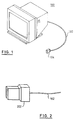
- FIG. 1 shows a computer monitor 100 with which the present invention may be used.
- the monitor includes an interface cable assembly 102 having at the end furthest from the monitor a connector 104 for connection to a personal computer or adapter card.
- FIG. 2 shows a first embodiment of the interface module, in which the connector 104 is enlarged to form a connector assembly 202 to take a circuit card, or a flexible circuit substrate containing the interface circuit (described later).
- This embodiment results in a very compact implementation of the interface module and allows use of existing types of bulk interface cable.
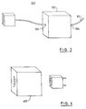
- FIG. 3 shows a second embodiment of the interface circuit.
- An interface cable assembly 300 comprises a cable 102 which is connected to the monitor at a first end.
- a small box 302 containing the interface circuitry forms the module, and is mounted on the interface cable 102, such that the interface cable 102 from the monitor enters the box 302 at a first end 304 and exits at a second end 306. Connections are made from the interface cable 102 to the interface circuitry contained within the box 302.
- This embodiment takes up a minimum of space at the rear of the personal computer/adapter card and allows a standard style of connector to be used to attach to the personal computer/adapter card.
- FIG. 4 shows a third embodiment of the interface circuit.
- a separate module 400 is used and the existing display interface cable connector 104 plugs into a first end of the module.
- the second end of the module plugs into the personal computer/adapter card.
- the interface circuit is contained within the module. This embodiment may be used as an upgrade to existing standard monitors without any internal modification.
- FIG. 5 shows a schematic diagram of an interface circuit, suitable for use between a monitor and a personal computer/adapter card to solve this problem. The function of two functional embodiments of the interface circuit will be described.
- Video signals for the Red, Green and Blue channels 501, 502, 503, and Horizontal synchronising signal 504 pass through the interface circuit unchanged and are not used in any way by the interface circuit.
- Vertical synchronising signal 505 and the ground signal 512 pass through the interface circuit unchanged, but are used by the interface circuit.
- the test line 506, which is an input to the monitor, is grounded, so that the monitor believes that it is connected to a personal computer/adapter and does not operate in a test mode.
- the key pin 507 has no connection.
- ID bits 0 through 3, (508, 509, 510, 511) from the monitor are not connected, the identification data for the particular monitor being predetermined within the Read Only Memory (ROM) contained in the interface circuit.
- ROM Read Only Memory
- a second functional embodiment of the functional aspects of the circuit is shown in figure 6.
- ID bits 0 through 3, from the monitor (508, 509, 510, 511) are connected to the circuit, the identification data for the particular monitor being determined by the 4 bit ID obtained from the ID bits and then translated into the relevant data to be sent to the personal computer/adapter card.
- the 4 bit ID may be used as an offset into the data contained in the ROM, thus determining which of the multiple sets of data stored in the ROM is communicated to the personal computer/adapter card.
- the special cases of ID bits 2 and 3 having a synchronisation signal present can be handled by a suitable monostable circuit detecting the transitions in the sync signal and providing an additional one or more address bits.
- the Extended Display Identification Data (EDID) circuit 520 contains a ROM, which has the information necessary to describe the monitor to the personal computer/adapter card.
- the EDID requires the following signals:
- DDC1 In a first mode of operation, called DDC1 by VESA, the circuit continually sends 128 bytes of information, containing details about the capability of the monitor, to the personal computer/adapter card using ID bit 1 as a data line, and the Vertical Sync line as a clock line.
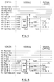
- DDC2B In a second mode of operation, called DDC2B by VESA, the clock and data signals are used by circuits in the personal computer/adapter card to retrieve information from the ROM concerning the description of modes supported by the monitor. Examples of the mode description information can be found in table 1 below. Note that DPMS stands for Display Power Management Signalling.
- DDC2AB In an optional third mode of operation, called DDC2AB by VESA, there is bi-directional communication between the personal computer/adapter card and the monitor. This allows, for example, the personal computer keyboard to be plugged into the monitor and keystroke data transferred from the monitor via the interface circuit. It also allows for access by the personal computer/adapter card to controls inside the monitor for the adjustment of, for example, image size and shape.
- Either of the embodiments of the functional aspects of the circuit may be extended to include other information from the monitor, such as its serial number, date of manufacture etc.
Landscapes
- Engineering & Computer Science (AREA)
- Radar, Positioning & Navigation (AREA)
- Remote Sensing (AREA)
- Physics & Mathematics (AREA)
- Computer Hardware Design (AREA)
- General Physics & Mathematics (AREA)
- Theoretical Computer Science (AREA)
- Controls And Circuits For Display Device (AREA)
Applications Claiming Priority (2)
| Application Number | Priority Date | Filing Date | Title |
|---|---|---|---|
| GB9420712A GB2294135A (en) | 1994-10-14 | 1994-10-14 | Apparatus for adding display data channel to existing display |
| GB9420712 | 1994-10-14 |
Publications (2)
| Publication Number | Publication Date |
|---|---|
| EP0708399A2 true EP0708399A2 (en) | 1996-04-24 |
| EP0708399A3 EP0708399A3 (enExample) | 1996-05-08 |
Family
ID=10762826
Family Applications (1)
| Application Number | Title | Priority Date | Filing Date |
|---|---|---|---|
| EP95306412A Withdrawn EP0708399A2 (en) | 1994-10-14 | 1995-09-13 | Apparatus for adding a display data channel to existing display |
Country Status (2)
| Country | Link |
|---|---|
| EP (1) | EP0708399A2 (enExample) |
| GB (1) | GB2294135A (enExample) |
Cited By (7)
| Publication number | Priority date | Publication date | Assignee | Title |
|---|---|---|---|---|
| EP0769748A1 (fr) * | 1995-10-19 | 1997-04-23 | STMicroelectronics S.A. | Cellule intégrable DDC dédiée à un microprocesseur |
| GB2314493A (en) * | 1996-06-18 | 1997-12-24 | Lg Electronics Inc | Monitor communicates with computer via serial peripheral interface |
| US6243780B1 (en) | 1996-11-29 | 2001-06-05 | Lg Electronics Inc. | Interface of a monitor communicating with personal computer |
| WO2002067234A3 (de) * | 2001-02-16 | 2003-12-31 | Siemens Ag | Displaymodul |
| WO2006019233A1 (en) * | 2004-08-16 | 2006-02-23 | Samsung Electronics Co., Ltd. | Display apparatus and display system |
| EP1564708A3 (en) * | 2004-02-11 | 2006-07-05 | Lg Electronics Inc. | TFT-LCD driving system and method thereof |
| US7089342B2 (en) | 1993-02-10 | 2006-08-08 | Hitachi, Ltd. | Method enabling display unit to bi-directionally communicate with video source |
Families Citing this family (3)
| Publication number | Priority date | Publication date | Assignee | Title |
|---|---|---|---|---|
| JPH10133995A (ja) * | 1996-05-13 | 1998-05-22 | Sun Microsyst Inc | コンピュータ・システムと周辺装置間の最適能力を選択する方法および装置 |
| DE19630941A1 (de) * | 1996-07-31 | 1997-10-09 | Siemens Nixdorf Inf Syst | TV-PC-Umsetzkabel und Rechnereinheit mit Funktionsschnittstelle für dieses Kabel |
| GB2330926A (en) * | 1997-11-03 | 1999-05-05 | Tdk Grey Cell Limited | Connecting a device and a computer |
Family Cites Families (6)
| Publication number | Priority date | Publication date | Assignee | Title |
|---|---|---|---|---|
| JPH02287593A (ja) * | 1989-04-28 | 1990-11-27 | Toshiba Corp | ディスプレイの接続状態判別方式 |
| US5276458A (en) * | 1990-05-14 | 1994-01-04 | International Business Machines Corporation | Display system |
| ES2084525T3 (es) * | 1990-05-14 | 1996-05-01 | Ibm | Sistema de visualizacion. |
| US5285197A (en) * | 1991-08-28 | 1994-02-08 | Nec Technologies, Inc. | Method and apparatus for automatic selection of scan rates for enhanced VGA-compatible monitors |
| DE9215701U1 (de) * | 1992-11-19 | 1993-01-07 | Wissing, Heimo, Dr.med. Dipl.-Ing., 6900 Heidelberg | Vorrichtung zum Anschluß von Bildschirmen an Personal-Computer |
| JPH06259050A (ja) * | 1993-02-16 | 1994-09-16 | Internatl Business Mach Corp <Ibm> | ビデオ・モニタ、ビデオ・アダプタ及びこれらの間の動的通信リンク生成方法並びにシステム |
-
1994
- 1994-10-14 GB GB9420712A patent/GB2294135A/en not_active Withdrawn
-
1995
- 1995-09-13 EP EP95306412A patent/EP0708399A2/en not_active Withdrawn
Non-Patent Citations (1)
| Title |
|---|
| None |
Cited By (14)
| Publication number | Priority date | Publication date | Assignee | Title |
|---|---|---|---|---|
| US7475181B2 (en) | 1993-02-10 | 2009-01-06 | Mondis Technology Ltd. | Display unit with processor and communication controller which communicates information to the processor |
| US7475180B2 (en) | 1993-02-10 | 2009-01-06 | Mondis Technology Ltd. | Display unit with communication controller and memory for storing identification number for identifying display unit |
| US7089342B2 (en) | 1993-02-10 | 2006-08-08 | Hitachi, Ltd. | Method enabling display unit to bi-directionally communicate with video source |
| EP0769748A1 (fr) * | 1995-10-19 | 1997-04-23 | STMicroelectronics S.A. | Cellule intégrable DDC dédiée à un microprocesseur |
| FR2740238A1 (fr) * | 1995-10-19 | 1997-04-25 | Sgs Thomson Microelectronics | Cellule integrable ddc dediee a un microprocesseur |
| US5884044A (en) * | 1995-10-19 | 1999-03-16 | Sgs-Thomson Microelectronics S.A. | Dedicated DDC integrable multimode communications cell |
| CN1118017C (zh) * | 1996-06-18 | 2003-08-13 | Lg电子株式会社 | 可与个人计算机通讯的显示器 |
| GB2314493B (en) * | 1996-06-18 | 1998-12-16 | Lg Electronics Inc | Monitor communicable with personal computer |
| GB2314493A (en) * | 1996-06-18 | 1997-12-24 | Lg Electronics Inc | Monitor communicates with computer via serial peripheral interface |
| US6243780B1 (en) | 1996-11-29 | 2001-06-05 | Lg Electronics Inc. | Interface of a monitor communicating with personal computer |
| WO2002067234A3 (de) * | 2001-02-16 | 2003-12-31 | Siemens Ag | Displaymodul |
| EP1564708A3 (en) * | 2004-02-11 | 2006-07-05 | Lg Electronics Inc. | TFT-LCD driving system and method thereof |
| US7561134B2 (en) | 2004-02-11 | 2009-07-14 | Lg Electronics Inc. | TFT-LCD driving system and method thereof |
| WO2006019233A1 (en) * | 2004-08-16 | 2006-02-23 | Samsung Electronics Co., Ltd. | Display apparatus and display system |
Also Published As
| Publication number | Publication date |
|---|---|
| GB2294135A (en) | 1996-04-17 |
| EP0708399A3 (enExample) | 1996-05-08 |
| GB9420712D0 (en) | 1994-11-30 |
Similar Documents
| Publication | Publication Date | Title |
|---|---|---|
| EP1111572B1 (en) | Display apparatus | |
| US8120612B2 (en) | Intelligent video graphics switcher | |
| US5423697A (en) | Modular communications connector for I/O card applications | |
| KR100373668B1 (ko) | 디스플레이 장치 | |
| US7295194B2 (en) | Apparatus and method for outputting different display identification data depending on type of connector | |
| US7009616B2 (en) | Multi-mode display | |
| CN101015180B (zh) | 链路延伸器 | |
| US7563129B2 (en) | Video signal transmitting device for computer system having analog and digital video signal output functionality | |
| EP1727020A2 (en) | Computer System and Display Apparatus | |
| US20040027515A1 (en) | Display apparatus, display system and cable | |
| US20080018584A1 (en) | Liquid crystal display module and liquid crystal display apparatus having the same | |
| US6600747B1 (en) | Video monitor multiplexing circuit | |
| EP0708399A2 (en) | Apparatus for adding a display data channel to existing display | |
| US20060114248A1 (en) | Displaying apparatus and control method thereof | |
| US5742273A (en) | Video monitor/adapter interconnect extension architecture | |
| KR970003088B1 (ko) | 비디오 모니터/어댑터 상호접속 확장 아키텍처 | |
| KR20070092785A (ko) | 표시 장치 및 이의 구동 방법 | |
| KR100433873B1 (ko) | 디지털 인터페이스로 연결된 기기들간의 hpd 구현 방법및 그 장치 | |
| CN213693924U (zh) | 一种监测视频转接状态的视频转接器 | |
| JP2005091795A (ja) | 表示装置 | |
| US20040233189A1 (en) | Display unit | |
| CN114265803A (zh) | 一种标准dp接口复用支持usb触摸屏的方法 | |
| US20040001053A1 (en) | System and method for providing a reference video signal | |
| CN215577630U (zh) | 一种模块化组合装配的多功能发送卡系统 | |
| KR100575125B1 (ko) | 디지털 영상표시기기의 dvi 신호입출력장치 |
Legal Events
| Date | Code | Title | Description |
|---|---|---|---|
| PUAI | Public reference made under article 153(3) epc to a published international application that has entered the european phase |
Free format text: ORIGINAL CODE: 0009012 |
|
| PUAL | Search report despatched |
Free format text: ORIGINAL CODE: 0009013 |
|
| AK | Designated contracting states |
Kind code of ref document: A2 Designated state(s): DE FR GB |
|
| AK | Designated contracting states |
Kind code of ref document: A3 Designated state(s): DE FR GB |
|
| STAA | Information on the status of an ep patent application or granted ep patent |
Free format text: STATUS: THE APPLICATION IS DEEMED TO BE WITHDRAWN |
|
| 18D | Application deemed to be withdrawn |
Effective date: 19961109 |