EP0708313B1 - Ultraschall-Durchflussmessgerät - Google Patents
Ultraschall-Durchflussmessgerät Download PDFInfo
- Publication number
- EP0708313B1 EP0708313B1 EP95116580A EP95116580A EP0708313B1 EP 0708313 B1 EP0708313 B1 EP 0708313B1 EP 95116580 A EP95116580 A EP 95116580A EP 95116580 A EP95116580 A EP 95116580A EP 0708313 B1 EP0708313 B1 EP 0708313B1
- Authority
- EP
- European Patent Office
- Prior art keywords
- ultrasound
- flow meter
- fitting
- meter according
- reflector surface
- Prior art date
- Legal status (The legal status is an assumption and is not a legal conclusion. Google has not performed a legal analysis and makes no representation as to the accuracy of the status listed.)
- Expired - Lifetime
Links
- 238000002604 ultrasonography Methods 0.000 claims abstract description 29
- 238000012545 processing Methods 0.000 claims description 6
- 238000009499 grossing Methods 0.000 claims description 4
- 238000009434 installation Methods 0.000 claims description 4
- 238000005259 measurement Methods 0.000 abstract description 8
- 238000004519 manufacturing process Methods 0.000 description 4
- 238000005266 casting Methods 0.000 description 3
- 238000010438 heat treatment Methods 0.000 description 3
- 238000003754 machining Methods 0.000 description 3
- 238000003801 milling Methods 0.000 description 3
- 238000012805 post-processing Methods 0.000 description 3
- 238000011156 evaluation Methods 0.000 description 2
- 239000007788 liquid Substances 0.000 description 2
- 238000005253 cladding Methods 0.000 description 1
- 230000002349 favourable effect Effects 0.000 description 1
- 238000005242 forging Methods 0.000 description 1
- 239000000463 material Substances 0.000 description 1
- 238000000691 measurement method Methods 0.000 description 1
- 239000002184 metal Substances 0.000 description 1
- 238000000034 method Methods 0.000 description 1
- 238000005498 polishing Methods 0.000 description 1
- 238000007789 sealing Methods 0.000 description 1
- XLYOFNOQVPJJNP-UHFFFAOYSA-N water Substances O XLYOFNOQVPJJNP-UHFFFAOYSA-N 0.000 description 1
Images
Classifications
-
- G—PHYSICS
- G01—MEASURING; TESTING
- G01F—MEASURING VOLUME, VOLUME FLOW, MASS FLOW OR LIQUID LEVEL; METERING BY VOLUME
- G01F1/00—Measuring the volume flow or mass flow of fluid or fluent solid material wherein the fluid passes through a meter in a continuous flow
- G01F1/66—Measuring the volume flow or mass flow of fluid or fluent solid material wherein the fluid passes through a meter in a continuous flow by measuring frequency, phase shift or propagation time of electromagnetic or other waves, e.g. using ultrasonic flowmeters
- G01F1/662—Constructional details
-
- G—PHYSICS
- G01—MEASURING; TESTING
- G01N—INVESTIGATING OR ANALYSING MATERIALS BY DETERMINING THEIR CHEMICAL OR PHYSICAL PROPERTIES
- G01N2291/00—Indexing codes associated with group G01N29/00
- G01N2291/02—Indexing codes associated with the analysed material
- G01N2291/028—Material parameters
- G01N2291/02836—Flow rate, liquid level
Definitions
- the present invention relates to an ultrasonic flow meter according to the preamble of claim 1 (DE 34 28 058 A1).
- Such flow meters are for example from the DE 35 44 456 A1 and EP 0 559 938 B1 are known.
- Openings are provided in the walls of the measuring section in which inserted an additional reflection part is. To compensate for tolerances is one of the reflection parts adjustable. This version points many items on.
- the object of the present invention is a as simple as possible, from as few parts as possible to create existing ultrasonic flow meter that particularly easy to manufacture, especially and can be installed without seals.
- an ultrasonic flow meter which has a fitting that can be flowed through by a medium, the fitting two in Flow direction arranged one behind the other, a measuring section defining ultrasound transceiver, the Fitting in the area of the measuring section on at least one wall side at least one ultrasound reflecting mirror surface for deflecting an ultrasonic signal, and wherein on another wall side in the area of the mirror surface Recess is arranged as a machining opening, especially designed for smoothing, for the mirror surface is.
- the interior of the fitting is the actual one Cross section, easily accessible. It is therefore possible in particular, the interior of the fitting the manufacturing process so that it is the ultrasound properly reflected.
- the recess is essentially on one of the mirror surfaces opposite wall side arranged. So that's a given direct access, including simple editing tools can be used.
- the recess can advantageously be closed with a cover, arranged on the at least one further mirror surface is. This means that the recess is used twice given.
- Two or more mirror surfaces can also be on the cover be arranged. This allows the recess to be made large, which also makes tools accessible for the processing is cheap.
- the mirror surface / s on the cover is / are preferably raised. So that's the cover can be designed from the outside smooth or without any survey.
- the recess advantageously extends approximately over the entire area of the measuring section in the direction of flow. In order to the entire measuring section is accessible for processing.
- the fitting is preferably designed as a cast part. Thereby is easy to manufacture.
- the valve advantageously has one arranged in the inflow area Swirl plate on. In this way, good measurement results achievable.
- the swirl plate is preferably in the valve poured, so - even with different materials - A unit is formed.
- the measuring section can be arranged off-center, which is one accommodates favorable flow guidance.
- the valve can additionally an installation point for a temperature sensor exhibit. This makes it possible to measure a quantity of heat given in the measuring section.
- the cover can, for example, as a cast, pressed or forged part be formed, the last embodiment preferred is.
- An inexpensive valve is preferred Cast part used.
- Such castings are relatively rough, however, as already mentioned, post-processing is possible.
- the flow meter is thereby very temperature resistant, e.g. B. up to 180 ° C instead of only 130 ° C in the prior art. This also makes it a high one Given compressive strength.
- the solution according to the invention can also be general are described as an ultrasonic flow meter with two Ultrasound transceivers and one formed by a wall Measuring channel, the wall with an ultrasound reflecting and an opening for passing a machining tool through for editing, especially for one Smoothing, the mirror surface is provided. That way the manufacture or processing of the mirror surface very much simple. Combinations with the above and below Details are of course possible.
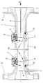
- the FIG shows a section through an ultrasonic flow meter.
- the flow meter essentially comprises a valve 1, the two flanges 2 in a not shown Pipeline is insertable.
- the valve 1 is from flows through any medium in the direction of arrow A.
- the medium is usually a liquid medium, often Water. But it is also possible that the medium is gaseous is.
- the fitting 1 forms with its wall or wall a measuring section or a measuring channel.
- the inflowing medium can be laminar or turbulent flow or have a swirl.
- a swirl plate 3 Inside the tap 1 is therefore a swirl plate 3 in the area of the inlet opening arranged. It serves to calm any turbulent eventuality Flow and eliminating a swirl. The measurement accuracy the arrangement can be increased.
- the swirl plate 3 is preferably cast into the fitting 1. This allows a relatively thin sheet of z. B. only 1.5 mm thick can be used. If the swirl plate 3 against it was cast, it should have a thickness of about 5 mm. With such a thickness, the swirl plate 3 cause eddies themselves which should be avoided.
- a temperature sensor 4 is arranged in the outlet of the fitting 1.
- the temperature sensor 4 can be screwed in, for example be. He is outside the armature 1 with one shown electronic evaluation unit connected. On in this way, for example, a quantity of heat can also be measured will. Depending on the application, the temperature sensor 4 can also dropped. In this case, the installation location for the Temperature sensor 4 of course closed, for. B. by a screw. Depending on the intended use of the fitting 1 the installation point can also be omitted entirely.
- the fitting 1 has two ultrasound transceivers 5, 6 on that in the direction of flow seen are arranged one behind the other.
- the ultrasound transceivers 5, 6 are e.g. B. by receiving parts 7 also screwed into the fitting 1.
- the ultrasound transceivers 5, 6 are also, like the temperature sensor 4, with connected to the electronic evaluation unit, not shown.
- the sealing of the union nuts 7 against the Armature 1 is made by O-rings 8.
- the transceiver 5 transmits to measure the flow rate an ultrasound signal from that on the deflecting mirror 9, the Mirror surface 10 and the deflecting mirror 11 to the transceiver 6 is supplied. Then the transceiver 6 transmits Ultrasonic signal from that the opposite way to the transceiver 5 is supplied. Because of the flow rate of the medium inside the fitting 1 results in Runtime difference between these two measurements. Thereby can deduce the flow rate from the difference in transit time will. This method of measurement is well known and for example in the magazine "Technisches Messen” TM, 1979, issue 4, page 145. On this measurement method is therefore not discussed in more detail below.
- the fitting 1 is preferably, in particular for reasons of cost, designed as a casting. It therefore has a relative rough surface, both inside and outside. In order to be able to reflect ultrasound well, however smooth surfaces needed as mirrors or reflectors can work.
- the fitting 1 is therefore in the area of the mirror surface 10 smoothed, e.g. B. by milling, if necessary also by subsequent polishing. To do this, the Mirror surface 10 of course still accessible after casting be.
- the fitting 1 therefore has in the area of the measuring section, defined by the ultrasound transceivers 5, 6 is a large recess, which is in operation is closed by the cover 12.
- the cover 12 is preferably releasably connected to the fitting 1, e.g. B. by means of screws (not shown). The seal between Armature 1 and cover 12 is ensured by the O-ring 13.
- the cover 12 is preferably a forged part. It is therefore possible, the deflecting mirror 9, 11 as integral parts the cover 12 form only after forging be processed finely.
- the mirror surface 10 is thus with the cover 12 removed a tool, e.g. B. a milling head for post-processing accessible to pouring.
- a tool e.g. B. a milling head for post-processing accessible to pouring.
- Mirror surface 10 with respect to the area surrounding it Faucet 1 raised.
- the milling head can therefore be used during machining leak gently.
- There is no step in the valve which in turn are the cause of eddies and thus measurement errors could.
- the temperature sensor 4 arranged in the outlet and not in the inlet of the valve 1.
- the swirl plate 3 is only required in the inlet area of the fitting 1, because a turbulent flow behind the measuring section for the measuring accuracy is irrelevant.
- the fitting 1 can therefore be kept more compact if the measuring section is off-center, d. H. more on the outlet side, is arranged.
- the flow meter according to the invention can, for example, in Heating systems or in the district heating supply for determination of the amount of heat removed.
- the flowmeter according to the invention in the return of Heating system arranged.
- a must in advance second temperature sensor can be arranged. It is also conceivable that flow meter in general for determination the amount of liquid or gas flowed through.
- Temperature of the medium can be determined.
Landscapes
- Physics & Mathematics (AREA)
- Electromagnetism (AREA)
- Fluid Mechanics (AREA)
- General Physics & Mathematics (AREA)
- Measuring Volume Flow (AREA)
- Ultra Sonic Daignosis Equipment (AREA)
- Pressure-Spray And Ultrasonic-Wave- Spray Burners (AREA)
Applications Claiming Priority (2)
| Application Number | Priority Date | Filing Date | Title |
|---|---|---|---|
| DE4437588A DE4437588A1 (de) | 1994-10-20 | 1994-10-20 | Ultraschall-Durchflußmeßgerät |
| DE4437588 | 1994-10-20 |
Publications (3)
| Publication Number | Publication Date |
|---|---|
| EP0708313A2 EP0708313A2 (de) | 1996-04-24 |
| EP0708313A3 EP0708313A3 (de) | 1996-06-12 |
| EP0708313B1 true EP0708313B1 (de) | 1998-06-10 |
Family
ID=6531310
Family Applications (1)
| Application Number | Title | Priority Date | Filing Date |
|---|---|---|---|
| EP95116580A Expired - Lifetime EP0708313B1 (de) | 1994-10-20 | 1995-10-20 | Ultraschall-Durchflussmessgerät |
Country Status (4)
| Country | Link |
|---|---|
| EP (1) | EP0708313B1 (da) |
| AT (1) | ATE167287T1 (da) |
| DE (2) | DE4437588A1 (da) |
| DK (1) | DK0708313T3 (da) |
Cited By (2)
| Publication number | Priority date | Publication date | Assignee | Title |
|---|---|---|---|---|
| EP2447681A2 (en) | 2010-10-14 | 2012-05-02 | AB Axis Industries | Ultrasonic flowmeter |
| US12442673B2 (en) | 2020-07-03 | 2025-10-14 | Huba Control Ag | Sensor assembly |
Families Citing this family (26)
| Publication number | Priority date | Publication date | Assignee | Title |
|---|---|---|---|---|
| EP0736751A3 (de) * | 1995-04-06 | 1998-07-08 | Siemens Aktiengesellschaft | Anordnung zur Verbrauchsmessung |
| DE19713526A1 (de) * | 1997-04-01 | 1998-10-08 | Elster Produktion Gmbh | Vorrichtung zur Ultraschall-Durchflußmessung |
| DE19729473A1 (de) * | 1997-07-10 | 1999-02-04 | Meinecke Ag H | Ultraschall-Durchflußmesser |
| DE19743340C3 (de) * | 1997-09-30 | 2003-09-25 | Siemens Ag | Durchflußmesser |
| SI20344A (sl) * | 1999-06-11 | 2001-02-28 | Iskraemeco D.D. | Merilna cev ultrazvočnega merilnika pretoka plinov |
| DE10047383C1 (de) * | 2000-09-25 | 2001-11-08 | Siemens Ag | Ultraschall-Durchflussmesser |
| DE10057188C8 (de) * | 2000-11-17 | 2016-10-06 | Endress + Hauser Flowtec Ag | Ultraschall-Durchflußmeßgerät mit Temperaturkompensation |
| DE10103745C2 (de) * | 2001-01-26 | 2003-04-17 | Hydrometer Gmbh | Ultraschallzähler mit einer austauschbaren Meßstrecke mit zentraler Fühleranbringung |
| DE10344894A1 (de) * | 2003-09-26 | 2005-04-21 | Bosch Gmbh Robert | Ultraschallströmungssensor mit zweiseitig abstrahlendem Ultraschallwandler |
| DE102004060062A1 (de) * | 2004-12-14 | 2006-06-29 | Robert Bosch Gmbh | Ultraschallmesseinrichtung |
| DE102005063313B4 (de) * | 2005-02-17 | 2010-01-28 | Hydrometer Gmbh | Durchflussmesser |
| DE102005062627B4 (de) * | 2005-12-23 | 2009-08-20 | Hydrometer Gmbh | Durchflussmesser |
| DE102006030942A1 (de) * | 2006-07-05 | 2008-01-10 | Landis+Gyr Gmbh | Durchflussmesser mit einem Einlaufbereich und einer Durchflussmessstrecke |
| DE102006038620A1 (de) * | 2006-08-17 | 2008-02-21 | Hydrometer Gmbh | Durchflussmesser |
| JP2008128727A (ja) * | 2006-11-17 | 2008-06-05 | Ricoh Elemex Corp | 超音波流量計 |
| JP5131815B2 (ja) * | 2007-04-13 | 2013-01-30 | 愛知時計電機株式会社 | 超音波流量計 |
| CH700175B1 (de) | 2007-07-19 | 2010-07-15 | Aquametro Ag | Durchflussmesseinrichtung. |
| JP2009168829A (ja) * | 2009-05-07 | 2009-07-30 | Panasonic Corp | 流量計測装置 |
| US8904881B2 (en) | 2010-05-12 | 2014-12-09 | Hydrometer Gmbh | Ultrasound transducer assembly and ultrasound flowmeter |
| DE102010020338A1 (de) | 2010-05-12 | 2011-11-17 | Hydrometer Gmbh | Gehäuseanordnung für Ultraschall-Durchflussmesser sowie Ultaschall-Durchflussmesser |
| CN102589751A (zh) * | 2011-12-10 | 2012-07-18 | 浙江恒森实业集团有限公司 | 一种超声波热量表及其提高性能的方法 |
| DE102013105922A1 (de) | 2013-06-07 | 2014-12-11 | Endress + Hauser Flowtec Ag | Ultraschall-Durchflussmessgerät |
| EP3617665B1 (en) * | 2018-08-29 | 2020-08-19 | Huba Control Ag | Ultrasonic flow meter |
| EP3800448B1 (en) | 2019-10-02 | 2023-12-20 | Huba Control Ag | Ultrasonic flow meter |
| WO2023139116A1 (en) * | 2022-01-19 | 2023-07-27 | Huba Control Ag | Flow meter |
| DE102023112508A1 (de) * | 2023-05-11 | 2024-11-14 | Krohne Ag | Vorrichtung für ein Ultraschalldurchflussmessgerät und Ultraschalldurchflussmessgerät |
Family Cites Families (8)
| Publication number | Priority date | Publication date | Assignee | Title |
|---|---|---|---|---|
| US4596133A (en) * | 1983-07-29 | 1986-06-24 | Panametrics, Inc. | Apparatus and methods for measuring fluid flow parameters |
| DE3544456A1 (de) * | 1985-12-16 | 1987-06-19 | Siemens Ag | Durchflussmessgeraet in ultraschalltechnik |
| FI900511A7 (fi) * | 1987-08-10 | 1990-02-01 | Siemens Ag | Ultraääni-virtaamamittauslaite |
| DE8901609U1 (de) * | 1989-02-13 | 1989-05-11 | Schröder, Hubert, 3320 Salzgitter | Schließvorrichtung für Schmuckketten |
| EP0559938B1 (de) * | 1992-03-11 | 1993-10-27 | Siemens Aktiengesellschaft | Durchflussmesseinrichtung für flüssige Medien nach dem Ultraschall-Laufzeitprinzip |
| DE4336368C2 (de) * | 1993-10-25 | 1995-08-03 | Siemens Ag | Vorrichtung zur Durchflußmessung |
| DE4336370C1 (de) * | 1993-10-25 | 1995-02-02 | Siemens Ag | Vorrichtung zur Durchflußmessung |
| DE4336369C1 (de) * | 1993-10-25 | 1995-06-22 | Siemens Ag | Vorrichtung zur Durchflußmessung |
-
1994
- 1994-10-20 DE DE4437588A patent/DE4437588A1/de not_active Withdrawn
-
1995
- 1995-10-20 EP EP95116580A patent/EP0708313B1/de not_active Expired - Lifetime
- 1995-10-20 DE DE59502485T patent/DE59502485D1/de not_active Expired - Lifetime
- 1995-10-20 AT AT95116580T patent/ATE167287T1/de not_active IP Right Cessation
- 1995-10-20 DK DK95116580T patent/DK0708313T3/da active
Cited By (2)
| Publication number | Priority date | Publication date | Assignee | Title |
|---|---|---|---|---|
| EP2447681A2 (en) | 2010-10-14 | 2012-05-02 | AB Axis Industries | Ultrasonic flowmeter |
| US12442673B2 (en) | 2020-07-03 | 2025-10-14 | Huba Control Ag | Sensor assembly |
Also Published As
| Publication number | Publication date |
|---|---|
| DE59502485D1 (de) | 1998-07-16 |
| DK0708313T3 (da) | 1999-03-22 |
| ATE167287T1 (de) | 1998-06-15 |
| EP0708313A3 (de) | 1996-06-12 |
| DE4437588A1 (de) | 1996-04-25 |
| EP0708313A2 (de) | 1996-04-24 |
Similar Documents
| Publication | Publication Date | Title |
|---|---|---|
| EP0708313B1 (de) | Ultraschall-Durchflussmessgerät | |
| DE10312034B3 (de) | Ultraschalldurchflußmeßverfahren | |
| DE10047383C1 (de) | Ultraschall-Durchflussmesser | |
| DE102004053142B4 (de) | Flanschwirbeldurchflußmesser mit unitären zulaufenden Erweiterungsstücken | |
| EP2044392B1 (de) | MESSSYSTEM FÜR EIN IN EINER PROZEßLEITUNG STRÖMENDES MEDIUM | |
| EP0303255A1 (de) | Ultraschall-Durchflussmesseinrichtung | |
| EP3404372B1 (de) | Ultraschalldurchflussmessgerät | |
| CH701728B1 (de) | Ultraschallmessanordnung mit einer Ultraschallmessstrecke aus Kunststoff, Verfahren zur Durchflussmessung und Verfahren zur Herstellung einer Ultraschallmessstrecke. | |
| EP2770304A1 (de) | Durchflussmesser mit einem in ein Gehäuse einsetzbaren Messeinsatz | |
| EP3199923A1 (de) | Ultraschall-durchflussmengenmesser | |
| DE102013202850A1 (de) | Durchflussmesser mit einem Schallwandler umfassenden Messeinsatz | |
| DE202017007116U1 (de) | Messeinheit, Leitungsstück und Durchflussmesser zur Bestimmung der Durchflussmenge | |
| EP2827111A1 (de) | Ultraschallzähler | |
| DE202012104853U1 (de) | Durchflussmengenmesser zur Bestimmung der Durchflussmenge eines Fluids | |
| EP0681162A1 (de) | Messwertgeber zur Messung von Flüssigkeitsströmungen mit Ultraschall | |
| EP0763717A2 (de) | Vorrichtung zur Ultraschall-Durchflussmessung | |
| DE19713526A1 (de) | Vorrichtung zur Ultraschall-Durchflußmessung | |
| DE9420760U1 (de) | Durchflussmesser | |
| EP3757527B1 (de) | Ultraschall-durchflussmessgerät | |
| DE3855311T2 (de) | Anordnung zur messung des volumenflusses eines ventilators | |
| EP3372961A1 (de) | Messeinheit, leitungsstück, durchflussmesser und verfahren zur bestimmung der durchflussmenge | |
| WO2006000546A1 (de) | Verfahren zur kalibrierung von ultraschall-clamp-on-durchflussmessgeräten | |
| DE2405786B2 (de) | Meßeinrichtung zur Gasstrommessung, insbesondere in Gasabsaugeleitungen | |
| DE4242444A1 (de) | Verfahren und Vorrichtung zum Prüfen und Eichen eines Durchflußvolumenzählers | |
| DE10235033B4 (de) | Durchflußmesser |
Legal Events
| Date | Code | Title | Description |
|---|---|---|---|
| PUAI | Public reference made under article 153(3) epc to a published international application that has entered the european phase |
Free format text: ORIGINAL CODE: 0009012 |
|
| AK | Designated contracting states |
Kind code of ref document: A2 Designated state(s): AT DE DK FR NL SE |
|
| PUAL | Search report despatched |
Free format text: ORIGINAL CODE: 0009013 |
|
| AK | Designated contracting states |
Kind code of ref document: A3 Designated state(s): AT DE DK FR NL SE |
|
| 17P | Request for examination filed |
Effective date: 19960706 |
|
| GRAG | Despatch of communication of intention to grant |
Free format text: ORIGINAL CODE: EPIDOS AGRA |
|
| 17Q | First examination report despatched |
Effective date: 19971028 |
|
| GRAG | Despatch of communication of intention to grant |
Free format text: ORIGINAL CODE: EPIDOS AGRA |
|
| GRAH | Despatch of communication of intention to grant a patent |
Free format text: ORIGINAL CODE: EPIDOS IGRA |
|
| GRAH | Despatch of communication of intention to grant a patent |
Free format text: ORIGINAL CODE: EPIDOS IGRA |
|
| GRAA | (expected) grant |
Free format text: ORIGINAL CODE: 0009210 |
|
| AK | Designated contracting states |
Kind code of ref document: B1 Designated state(s): AT DE DK FR NL SE |
|
| REF | Corresponds to: |
Ref document number: 167287 Country of ref document: AT Date of ref document: 19980615 Kind code of ref document: T |
|
| REF | Corresponds to: |
Ref document number: 59502485 Country of ref document: DE Date of ref document: 19980716 |
|
| ET | Fr: translation filed | ||
| REG | Reference to a national code |
Ref country code: DK Ref legal event code: T3 |
|
| PLBE | No opposition filed within time limit |
Free format text: ORIGINAL CODE: 0009261 |
|
| STAA | Information on the status of an ep patent application or granted ep patent |
Free format text: STATUS: NO OPPOSITION FILED WITHIN TIME LIMIT |
|
| 26N | No opposition filed | ||
| PGFP | Annual fee paid to national office [announced via postgrant information from national office to epo] |
Ref country code: FR Payment date: 20021025 Year of fee payment: 8 |
|
| NLS | Nl: assignments of ep-patents |
Owner name: LANDIS+GYR GMBH |
|
| PG25 | Lapsed in a contracting state [announced via postgrant information from national office to epo] |
Ref country code: FR Free format text: LAPSE BECAUSE OF NON-PAYMENT OF DUE FEES Effective date: 20040630 |
|
| REG | Reference to a national code |
Ref country code: FR Ref legal event code: ST |
|
| PGFP | Annual fee paid to national office [announced via postgrant information from national office to epo] |
Ref country code: AT Payment date: 20040929 Year of fee payment: 10 |
|
| PGFP | Annual fee paid to national office [announced via postgrant information from national office to epo] |
Ref country code: SE Payment date: 20041028 Year of fee payment: 10 |
|
| PGFP | Annual fee paid to national office [announced via postgrant information from national office to epo] |
Ref country code: NL Payment date: 20041031 Year of fee payment: 10 |
|
| PG25 | Lapsed in a contracting state [announced via postgrant information from national office to epo] |
Ref country code: AT Free format text: LAPSE BECAUSE OF NON-PAYMENT OF DUE FEES Effective date: 20051020 |
|
| PG25 | Lapsed in a contracting state [announced via postgrant information from national office to epo] |
Ref country code: SE Free format text: LAPSE BECAUSE OF NON-PAYMENT OF DUE FEES Effective date: 20051021 |
|
| PG25 | Lapsed in a contracting state [announced via postgrant information from national office to epo] |
Ref country code: NL Free format text: LAPSE BECAUSE OF NON-PAYMENT OF DUE FEES Effective date: 20060501 |
|
| EUG | Se: european patent has lapsed | ||
| NLV4 | Nl: lapsed or anulled due to non-payment of the annual fee |
Effective date: 20060501 |
|
| PGFP | Annual fee paid to national office [announced via postgrant information from national office to epo] |
Ref country code: DK Payment date: 20131024 Year of fee payment: 19 |
|
| PGFP | Annual fee paid to national office [announced via postgrant information from national office to epo] |
Ref country code: DE Payment date: 20131218 Year of fee payment: 19 |
|
| REG | Reference to a national code |
Ref country code: DE Ref legal event code: R119 Ref document number: 59502485 Country of ref document: DE |
|
| PG25 | Lapsed in a contracting state [announced via postgrant information from national office to epo] |
Ref country code: DE Free format text: LAPSE BECAUSE OF NON-PAYMENT OF DUE FEES Effective date: 20150501 |
|
| REG | Reference to a national code |
Ref country code: DK Ref legal event code: EBP Effective date: 20141031 |
|
| PG25 | Lapsed in a contracting state [announced via postgrant information from national office to epo] |
Ref country code: DK Free format text: LAPSE BECAUSE OF NON-PAYMENT OF DUE FEES Effective date: 20141031 |