EP0707896A1 - Device for applying glue and its nozzle plate - Google Patents
Device for applying glue and its nozzle plate Download PDFInfo
- Publication number
- EP0707896A1 EP0707896A1 EP95116217A EP95116217A EP0707896A1 EP 0707896 A1 EP0707896 A1 EP 0707896A1 EP 95116217 A EP95116217 A EP 95116217A EP 95116217 A EP95116217 A EP 95116217A EP 0707896 A1 EP0707896 A1 EP 0707896A1
- Authority
- EP
- European Patent Office
- Prior art keywords
- outlet openings
- conveying direction
- rows
- row
- nozzle plate
- Prior art date
- Legal status (The legal status is an assumption and is not a legal conclusion. Google has not performed a legal analysis and makes no representation as to the accuracy of the status listed.)
- Granted
Links
Images

Classifications
-
- B—PERFORMING OPERATIONS; TRANSPORTING
- B05—SPRAYING OR ATOMISING IN GENERAL; APPLYING FLUENT MATERIALS TO SURFACES, IN GENERAL
- B05C—APPARATUS FOR APPLYING FLUENT MATERIALS TO SURFACES, IN GENERAL
- B05C5/00—Apparatus in which liquid or other fluent material is projected, poured or allowed to flow on to the surface of the work
- B05C5/02—Apparatus in which liquid or other fluent material is projected, poured or allowed to flow on to the surface of the work the liquid or other fluent material being discharged through an outlet orifice by pressure, e.g. from an outlet device in contact or almost in contact, with the work
- B05C5/027—Coating heads with several outlets, e.g. aligned transversally to the moving direction of a web to be coated
Definitions
- the invention relates to a device of the type corresponding to the preamble of claim 1 and a nozzle plate suitable therefor.
- Such devices are mainly used for applying glue or the like to flat gluing material such as blanks or webs of cardboard, paper, textile, nonwoven and the like according to a predetermined pattern.
- the term "fluid application medium such as glue or the like” does not only include other adhesives such as adhesives or hot-melt adhesives, but also means that the invention extends to any application media which, in terms of consistency and physical behavior, is suitable for application with the device Have properties.
- other fluid media in particular viscous media such as lubricants and lacquers and possibly also gases, are therefore suitable as application media if these are to cause chemical reactions in the area of impact on the substrate, for example.
- the substrate will generally pass the fixed device in a flat path. It In principle, however, the substrate can also be fixed and the application device can be moved. Application systems with a combined movement of application device and substrate are also not excluded.
- slot nozzles are used in many cases, as are known from EP 224 855 A2. Such slot nozzles serve their purpose as long as the relative speed of the substrate is not too high compared to the application device.
- the starting point of the invention was, however, the problem of creating strip-shaped glue tracks with an application quantity of 8 to 10 g / m 2 within the track at speeds of over 2OO up to over 6OO m / min. Such speeds occur in the cigarette industry when it comes to applying the glue traces for the longitudinal seam of the cigarette and for sticking the filter and sticking the filter cover paper around the mouthpiece.
- the lack of precision in the width of the glue track in the case of slot nozzles is due to the fact that, given the small application quantities required and the very high conveying speeds of the substrate, the substrate speed is already noticeably higher than the exit speed of the glue from the nozzle.
- the glue strand is stretched in the longitudinal direction after emerging from the nozzle and, because of the constant volume, cannot otherwise constrict in the width direction. This constriction depends on the current conveying speed of the application medium and on the conveying speed of the substrate and therefore fluctuates depending on the operating conditions.
- An application head is known from a company publication of Dittberner GmbH "Cold glue application device" at which a series of small holes of 0, 7 or 1, O mm are arranged side by side perpendicular to the direction of conveyance.
- Cold glue application device at which a series of small holes of 0, 7 or 1, O mm are arranged side by side perpendicular to the direction of conveyance.
- this embodiment too, there is the constricting effect, but this leads here to the glue threads emerging from the individual bores being separated from one another and being deposited on the substrate as individual threads which have no connection to one another transversely to the conveying direction. There is therefore no desired glue track with glue coating that is uniform over the width of the glue track.
- the invention has for its object to provide an application device for the application media in question, by means of which a strip-shaped track can be generated with a width that can be maintained as precisely as possible and evenly distributed over the width of the track, even at very high relative speeds of the substrate to the application device.
- the constriction effect still occurs at the outermost outlet openings of the track and there leads to a lateral constriction of a few percent of the width of the outlet opening there.
- the width error is negligibly small. The reason for this is the division of the entire order into a large number of very small outlet openings, the constriction inside the overall width being masked by the cohesion of the adjacent edges of the individual strands there.
- the cross-sectional dimension for the outlet openings is about 0.2 to 2.0 mm.
- the “row” is to be understood as the connection line of the center points of exit openings adjacent to one another in the transverse direction.
- the clear distance between the outlet openings of the row located in the conveying direction corresponds substantially to the diameter of the outlet openings of the row downstream in the conveying direction.
- the strands of the application medium emerging from the individual outlet openings therefore just touch each other.
- the diameters of the outlet openings of the two rows are equal to one another and, for example, 0.5 mm (claim 6).
- the outlet openings of one and the same row can have the same diameter, which has advantages for manufacturing reasons (claim 8), or can be different (claim 9), in particular a reduction in the diameter of the terminal outlet openings can be expedient in order to reduce the influence of the constriction at the edge to minimize the order.
- the rows of outlet openings should follow one another closely to promote the formation of a coherent track of the application medium.
- the distance in the conveying direction should at most correspond approximately to the diameter of the outlet openings of one of the rows.
- An overlap according to claim 12 can also be recommended with regard to the arrangement in the longitudinal direction, i.e. the rear outlet openings in the conveying direction should engage a little into the gaps between the adjacent front outlet openings. This also promotes the formation of a coherent track of the application medium, because the strand of the application medium from the respective rear outlet opening can already touch the edges of the strands from the adjacent front outlet openings and merge with them before the speed-related lateral constriction plays an important role.
- the outlet openings are arranged in straight rows perpendicular to the conveying direction of the substrate (claim 13) and the outlet openings have a circular cross section (claim 14).
- the outlet openings can be formed by bores of corresponding diameter, which have been produced with twist drills, by electroerosive means or in a similar manner.
- outlet openings do not necessarily have to have a circular cross section. They also do not have to be completely separate from one another in the boundary surface in which they open.
- outlet openings as grooves alternately adjoin one another from different sides on a plane and in the direction of the plane.
- a type of manufacture of such an outlet opening arrangement which is important in practice is the subject of claim 18.
- the application head is divided, and the parts have the grooves in the adjoining dividing surfaces, which can be milled with a suitable tool, namely with a multiple tool several at the same time. Compared to drilling the outlet openings, this represents a simplification in terms of production.
- the application head on which the boundary surface with the discharge openings is formed, is generally made of steel of an already increased hardness, it has been shown that it is precisely at the outlet openings of small cross-sectional dimensions, through which the glue or the like also contributes to the high desired substrate speeds must be pushed through at high speed, show noticeable signs of wear over time.
- the embodiment according to claim 19 is expedient, in which the outlet area is made of a material with increased wear resistance.
- the wear occurs predominantly only in the exit area, so that only this matters. A Manufacturing the entire application head from the material with increased wear resistance would be too expensive and unnecessary outside the exit area.
- the bar be made of an electrically conductive hard material, i.e. made of a hard metal or an electrically conductive ceramic (cermet).
- the reason for the electrical conductivity is that in such materials the fine outlet openings can no longer be drilled with twist drills because the materials may be harder than the drills. Rather, the outlet openings are introduced with an electroerosive device, which requires the workpiece to be conductive.
- the bar can also be composed of individual pieces, but it is preferred if it extends continuously over the entire width of the application head.
- outlet openings are provided in a nozzle plate which can be attached to an application head and which can be unscrewed from the application head when the application pattern is changed without the application head itself having to be dismantled (claim 23).
- the invention is also implemented in such a nozzle plate, which can be designed according to claim 24.
- the distribution chamber is important in order to ensure a uniform exit of the application medium from all outlet openings emerging from the distribution chamber.
- Claim 25 is directed to the presence of a tear-off edge which ensures the smooth transition of the strands or the trace of the application medium to the substrate.
- the tear-off edge is in itself generally known prior art and can be seen, for example, from the Dittberner GmbH company document and from DE 35 O6 393 A1.
- the embodiment according to claim 27 permits continuous lateral connection of application traces generated by adjacent distribution chambers transverse to the conveying direction.
- the invention is also realized according to claim 28 in the important application example of a cigarette manufacturing machine, in which a device for applying strip-shaped glue traces to the cigarette paper or the filter paper comprises features of one of claims 1 to 23 or a nozzle plate with features of one of claims 24 to 27 .
- FIG. 1 shows the application of a strip-shaped application track 1 of a glue to a substrate 2 from a slot nozzle, which is only represented by a line representing the outlet slot 3.
- the substrate 2 for example a paper web or a paper band, runs past the fixed outlet nozzle 3 at a short distance in the direction of the arrow 4.
- the width of such a glue track 1 can be a few millimeters to a few tens of millimeters.
- the width of the glue track 1 essentially corresponds to the width 5 of the outlet nozzle 3.
- the speed is increased to a few hundred meters per minute, it is above the exit speed of the glue from the exit slot 3.
- the glue strand is thereby stretched in the longitudinal direction before it is completely deposited on the substrate 2 and thereby laces laterally in the 1 apparent from its original width 5 to a smaller width 6, which forms the width of the glue track 1 achievable with the outlet slit 3 at the relevant speed.
- the constriction is exaggerated. It is actually in the range of a few%, usually less than about 10%.
- the constriction can also change, so that the desired glue track of defined width cannot be achieved at high speeds with the known exit slot.
- Width fluctuations in the size arrangement in question are particularly unacceptable for the cigarette industry, where the task is to keep the order width as precise as possible, even at very high speeds of up to 600 m / min.
- an application head is shown, with the help of which the width of the trace of an application medium such as glue can be better maintained even at high speeds.
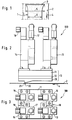
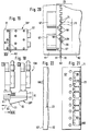
- FIGS. 2 and 3 designated as a whole by 100, which has a cuboidal application head designated as a whole by 10, on the upper side of which, in the operating position, four identical glue valves 13, 14, 15, 16 Connections 17, 18 for the supply of glue and electrical energy for valve control are arranged.
- the application head 10 comprises a plate-shaped carrier 11 with internal openings for the glue, a channel plate 12 arranged underneath with internal channels for distributing the glue and a nozzle plate 20 with a tear-off edge 21 and an arrangement of outlet openings 29, designated as a whole with 30, from which the Glue is dispensed onto the top of the substrate 2 conveyed past or close to it in the direction of arrow 4, specifically controlled by the glue valves 13, 14, 15, 16 that can be electrically controlled due to the high switching frequency.
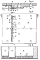
- FIG. 4 shows the nozzle plate 20 in longitudinal section. It contains blind holes 19 for screws, by means of which the nozzle plate 20 is screwed to the channel plate 12 and the support 11.
- the decisive area is marked by the circle Z.
- the nozzle part 2O has in its rear part an inclined underside 7 which rises slightly against the flat top 8 against the conveying direction 4. Near the area of the arrangement 30 of the outlet openings 29, the underside 7 merges into a boundary surface 23 which extends at least over the area of this arrangement 30 and is flat and parallel to the substrate 2.
- Distribution chambers 24, 25, 26 extend from the upper side 8, ie the supply side of the nozzle plate 20, into the depth of the nozzle plate 20, through which holes 27 28 are approximately perpendicular to the top 8 of the nozzle plate 2O and to the top of the substrate 2, which open out in the boundary surface 23 into the outlet openings 29, which thus forms the common outlet surface given by the metallic surface of the nozzle plate 2O for the outlet openings 29, which in the
- the embodiment is flat, but this should not preclude curved exit surfaces.
- the distributor chambers 24 are elongated grooves milled into the nozzle plate 20 from above, the bottom 27 of which is almost completely covered by the arrangement 30 of the outlet openings 29.
- one distributor chamber 24, 25, 26 results in a glue track of corresponding width on the substrate 2.
- the arrangement 30 of the outlet openings 29 or of the individual distributor chambers 24, 25, 26 depends on the desired gluing pattern.
- the gluing image is symmetrical to the longitudinal median plane M, i.e. the same distribution chambers 24 ', 25', 26 'are provided in mirror image on the opposite side of the longitudinal center plane M. This arrangement enables a gluing image according to FIG. 24, which will be explained in detail there.
- the distributor chambers 24, 25, 26 have flat connecting channels 34, 35, 36 in the upper side of the nozzle plate 20, into which feed channels of the channel plate 12 open.
- the glue entering from the channel plate 12 from above is deflected horizontally in the feed channels 34, 35, 36 and then again vertically deflected into the distribution chambers 24, 25, 26. This multiple deflection is important for the uniform distribution of the glue in the distribution chambers 24, 25, 26.
- the relatively large flow cross section of the distributor chambers 24, 25, 26 also serves this purpose, which considerably exceeds the total cross section of all the bores 28 opening into the respective distributor chamber and forming the outlet openings 29.
- the distributor chambers 24, 25, ... have a common center line N, which extends transversely to the conveying direction 4 of the substrate 2. They are close to the tear-off edge 21.
- FIG. 7 shows a view against the underside of the arrangement 30 of the outlet openings 29 in the region of the nozzle plate 20 denoted by the circle Z in FIG. 4.
- the individual bores 28 forming the outlet openings 29 in the exemplary embodiment shown have a diameter 31 of 0.5 mm.
- the outlet openings 29 are arranged in two rows staggered in the conveying direction 4, namely in a front row 32 located in the conveying direction and in a row 33 following in the conveying direction 4.
- the clear distances 37 between two adjacent outlet openings 29 of the front row 32 correspond to the diameter 31 of the bores 28.
- the clear distance 38 between the outermost positions of the rear boundary of the row 32 and the front boundary of the row 33 also corresponds to the diameter 31.
- the outlet openings 29 of the rear row 33 are exactly at a gap to the adjacent outlet openings 29 of the front row 32.
- the bore diameters are all identical to one another in FIGS. 7 and 9, but this is not mandatory.
- the bores 28 of the rear row 33 could have a larger diameter than those of the front row 32, which would then have to be moved apart accordingly.
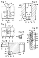
- the outlet openings 29 are generally moved as close as possible to the tear-off edge 21, which is formed on a shoulder 22 (FIGS. 1 and 8) of the underside of the nozzle plate 20 pointing in the conveying direction 4.
- the lower edge of the shoulder 22, which represents the tear-off edge 21, is near to the rear by a bevel 39 'relative to the front boundary of the distributor chamber 24 the outlet openings 29 relocated.
- the bevel 39 'forms an angle ⁇ of 30 ° with a plane perpendicular to the conveying direction 4 (FIG. 8).
- a shallow depression 39 has been worked out in relation to the area on the right, which is to create space for the application medium on the substrate 2 when it is adjacent to the boundary surface 23 Arrangement 30 of the outlet openings 29 is conveyed past.
- FIG. 9 shows a modified exemplary embodiment in which the outlet openings 29 of the front row 32 have moved even closer to the tear-off edge 21.
- the clear distance between two adjacent outlet openings 29 of the front row 32 is 10% smaller than the diameter of the outlet openings 29 of the rear row 33.
- a distance corresponding to the distance 38 between the rear and front boundaries of the rows 32 and 33 no longer exists; rather, the outlet openings 29 of the rear row 33 are pushed forward by about 10% of their diameter between the outlet openings 29 of the front row 32, so that the glue strand emerging from the outlet openings 29 of the rear row immediately makes contact on the sides with those from the adjacent front row Outlet openings 29 exits glue strands at their lateral boundaries.
- Fig. 9 it is indicated by the center lines of the rows 32, 33 that the sequence of bores should continue downwards and upwards, as the width of the glue strip to be produced requires. However, if this glue strip is only to have a small width of approximately 2 mm, the configuration of four bores 28 shown can be sufficient.
- the distributor chamber does not have to consist of an elongated groove, but can be formed by a blind bore which is introduced into the nozzle plate 2O from the top 8 and the outline of which is indicated by the dash-dotted circle K.
- the advantage of the arrangements 30 of outlet openings 29 shown in FIGS. 7 and 9 is particularly noticeable at high speeds of the substrate 2 compared to the application device 100.
- the nozzle plate 20 including the region of the outlet openings 29, was produced in one piece.
- a bar 65 is inserted in the corresponding area 64 of the base body of the nozzle plate 20' in the outlet region, which extends across its width, that is to say perpendicular to the drawing plane according to FIG. 10, which consists of a wear-resistant material, for example a hard material such as hard metal or a cermet.
- the strip 65 is aligned with its front 65 ′ with the shoulder 22 and forms with its underside 65 ′′ the boundary surface 23 in which the outlet openings 29 flow out.
- the strip 65 is fastened to the base body of the nozzle plate 20 'by means of screws which pass through holes 66 in the strip 65, which are offset from the sectional plane of FIG. 10 perpendicular to the plane of the drawing and which are shown in FIG. 11.
- the cross section of the strip 65 is approximately square in the exemplary embodiment shown, but can also be rectangular, for example.
- the pattern of the arrangement and formation of the bores 28 namely continues continuously over the adjacent boundaries 24 ′′ and 25 ′′ of the distributor chambers 24, 25.
- the rows 32, 33 of the bores 28 continue from one distribution chamber 24 into the other distribution chamber 25 without interrupting or changing the division.
- the existence of two distribution chambers 24, 25 cannot be determined at all from the bore pattern. This then also applies to the glue track produced with the arrangement according to FIG. 12, in which the portion produced by the distribution chamber 24 laterally merges with the portion generated by the distribution chamber 25 without the separation point appearing.
- FIG. 13 shows a detail from the arrangement 30 of the outlet openings 29 corresponding to FIG. 7 in a greatly enlarged manner in order to explain the function of the invention even further.
- the outlet openings 29 are arranged in two rows 32, 33, and the outlet openings of the outlet openings 29 of the row 32 located in the direction of movement 4 of the paper or other substrate are at a gap to the outlet openings 29 of the row 33.
- the traces of application 48 of the row 33 are laced at 46 a little in the transverse direction.
- the diameters and spacings of the outlet openings 29 are coordinated with one another in such a way that the outlet tracks 48 in the row 33 come into contact with the outlet tracks 48 in the row 32 at approximately points 47 and both groups of outlet tracks 48 merge with one another at the lateral edges, so that a uniform order of greater width is achieved.
- the lateral boundaries 48 'of the application tracks 48 disappear shortly after touching the application tracks 48 and are therefore only shown in dashed lines in FIG. 13 for a short piece.
- the outlet openings 29 are arranged in two rows 32, 33, one behind the other in the direction of movement 4. However, this is not mandatory.
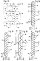
- 14 to 17 show exemplary embodiments with more than two rows of outlet openings 29 arranged one behind the other in the direction of movement 4.
- FIG. 14 three rows 52, 53, 54 arranged one behind the other in the direction of movement 4 are each arranged on rectified, ie parallel oblique lines 56 in a distributor chamber 24.
- the principle here is also that in Transverse direction adjacent outlet openings 29 are dimensioned and arranged so that the traces of application in the transverse direction of adjacent outlet openings of the different rows 52, 53, 54 touch and merge at the lateral edges.
- An example is identified in Figure 14 above.
- the application track of the outlet opening 29 of the row 54 touches with its lower longitudinal edge the application track of the outlet opening 29 ′′ of the middle row 53 and with its upper longitudinal edge the application track of the outlet opening 29 ′ of the front row 52.
- the angle 49 which the oblique lines 56 make to the direction of movement 4 is only approximately 25 ° in the exemplary embodiment in FIG. 14, while the corresponding angle 49 'in that 15 is approximately 45 °.
- the outlet openings 29 are provided in four rows 52, 53, 54, 55 in succession in the direction of movement 4 in relatively close succession.
- the oblique lines 57 need to be inclined to a greater extent.
- the oblique lines 58 are arranged in a zigzag, i.e. there are four outlet openings 29 each on oblique lines 58 which form an angle of approximately 90 ° to one another.
- Four rows 52, 53, 54, 55 in succession in the direction of movement are also formed here.
- outlet openings 29 are of the same diameter. This also applies to the outlet openings 29 located in the interior of the distribution chamber 24 in FIG. 16. Only the two terminal, ie outermost outlet openings 29 ''', which are the edges 60' of the order strip 60 produced overall limit are somewhat reduced in diameter in order to further reduce the slight influence of the constriction of the application track (46 in FIG. 13).
- FIG. 17 corresponds to the arrangement of the outlet openings 29 in three rows 52, 53, 54 on parallel inclined lines 59 of FIG. 14.
- the outlet openings 29 1 of the row 53 have a larger diameter than the outlet openings 29 of the row 52 and the outlet openings 292 of the row 54 in turn have a larger diameter than the outlet openings 291 of the row 53.
- the diameters of the outlet openings 292 are approximately twice as large as those of the outlet openings 29.
- the application device 100 of FIG. 2 is shown again in a reduced form, which, however, in this case comprises a nozzle plate 20 ′′, which runs along a plane 63 perpendicular to the substrate (not shown) and to the conveying direction 4 into a left-hand side according to FIG. 18 , ie in the conveying direction 4 angled part and a right part 62 as shown in FIG. 18 is divided.
- the parts 61, 62 are opposed to one another with the flat dividing surfaces 61 'and 62' and connected to one another by screws 67 perpendicular to the plane 63.
- the outlet openings 29 are formed by adjacent grooves 68, which are provided in the mutually opposite dividing surfaces 61 ', 62' of the parts 61, 62.
- flat chambers 69 are formed in the dividing surface 62 ′ and are supplied with glue or the like evenly via channels 70.
- An edge 71 of a few millimeters remains between the chambers 69 and the boundary surface 23 containing the outlet openings 29 Stand width, in which the grooves 68 are milled perpendicular to the boundary surface 23, for example as rectangular grooves with a depth of 0.5 mm and a width of 1 mm.
- the webs 72 that remain between the grooves 68, 68 are as wide as the grooves 68.
- a corresponding groove pattern is milled into the dividing surface 61 'of the part 61, the grooves 68 of which have the same dimensions, but are offset by a groove width in the width direction of the nozzle plate 20' '.
- the webs 72 between the grooves 68 on one side therefore close the grooves 68 on the other side, so that all of the grooves 68 adjoin the plane 63 and adjacent grooves in the plane 63 in the transverse direction of the path abut a common plane 73 perpendicular to the boundary surface 23 or to the substrate and located in the conveying direction.
- FIGS. 18 to 22 there are again rows 32, 33 of outlet openings 29 which lie one behind the other in the conveying direction and which separate glue threads can emerge which immediately touch in the transverse direction after the outlet and form a continuous glue track in the transverse direction.
- FIGS. 23, 24 An application example is shown schematically in FIGS. 23, 24.
- This shows a sub-assembly 200 from a cigarette manufacturing machine. It is about attaching the paper mouthpiece to filter cigarettes.
- the cigarettes 40 are produced in another part of the cigarette manufacturing machine as double cigarettes, which are still sitting together with the filter ends. These double cigarettes 40 are conveyed up by a conveying device 41.
- a paper strip 42 runs in from the other side and forms the mouthpiece for the double cigarettes 40 which is glued around the cigarette.
- the paper strip 42 must be as shown in FIG. 24 Patterns are glued, which happens with the aid of the application device 100, which has the nozzle plate 20 of FIG. 5 for this purpose.
- In the middle of the paper strip 42 there is a narrow glue-free strip 45, laterally at a distance from it in each case a series of glue-free rectangles 44 which contain fine perforations which are produced with a laser beam for the supply of secondary air when smoking.
- the gluing strips resulting in the pattern of FIG. 24 are provided in FIG. 24 with the reference numbers of the associated distribution chambers and an underline.
- the leftmost location in Fig. 24 relatively wide Beleimungsst Shape 24 is generated by the distribution chamber 24.
- the interrupted glue strip 24 is generated by the distribution chamber 25, which is switched on and off in rhythm.
- the continuous gluing strip 26 which is produced by the distribution chamber 26 , is adjacent to the center.
- the glue-free narrow strip 45 remains in the middle, where the separating knife later attaches. This strip 45 is caused by the clear distance between the distribution chambers 26 and 24 'in the region of the longitudinal center line M (FIG. 5).
- the web 42 of the tip paper provided with glue in the application device 100 according to the pattern of FIG. 24 runs into an apparatus 43, which is only indicated as a box, in which a section of the band 42 is looped in the middle around a double cigarette 40, glued and in Transverse direction is separated, whereupon the double cigarette 40 now provided with a double mouthpiece in the middle is divided into two single cigarettes 40 'and 40' ', as indicated on the left in FIG. 23.
- the web 42 of the tip paper has a speed of over 200 m / min when it passes the application device 100.
- the gluing must be very thin and even, because any unevenness leads to disruptions in the processing of the cigarettes and, under certain circumstances, also to taste impairments. also narrow tolerances of the gluing width in the transverse direction must be observed, which is achieved by the arrangement 30 of the outlet openings 29.
Abstract
Description
Die Erfindung bezieht sich auf eine Vorrichtung der dem Oberbegriff des Anspruchs 1 entsprechenden Art sowie eine dafür geeignete Düsenplatte.The invention relates to a device of the type corresponding to the preamble of claim 1 and a nozzle plate suitable therefor.
Derartige Vorrichtungen werden hauptsächlich zur Aufbringung von Leim oder dergleichen auf flaches Beleimungsgut wie Zuschnitte oder Bahnen aus Karton, Papier, Textil, Vlies und dergleichen nach einem vorbestimmten Muster verwendet. Der Ausdruck "fluides Auftragsmedium wie Leim oder dergleichen" schließt jedoch nicht nur andere Klebemittel wie Klebstoffe oder Heißschmelzkleber ein, sondern bedeutet auch, daß sich die Erfindung auf jegliche Auftragsmedien erstreckt, die von der Konsistenz und dem physikalischen Verhalten her zur Aufbringung mit der Vorrichtung geeignete Eigenschaften aufweisen. Als Auftragsmedien kommen daher außer dem Leim auch andere fluide Medien, insbesondere viskose Medien wie Schmiermittel und Lacke sowie gegebenenfalls auch Gase in Betracht, wenn diese in dem Auftreffbereich auf dem Substrat beispielsweise chemische Reaktionen hervorrufen sollen.Such devices are mainly used for applying glue or the like to flat gluing material such as blanks or webs of cardboard, paper, textile, nonwoven and the like according to a predetermined pattern. However, the term "fluid application medium such as glue or the like" does not only include other adhesives such as adhesives or hot-melt adhesives, but also means that the invention extends to any application media which, in terms of consistency and physical behavior, is suitable for application with the device Have properties. In addition to the glue, other fluid media, in particular viscous media such as lubricants and lacquers and possibly also gases, are therefore suitable as application media if these are to cause chemical reactions in the area of impact on the substrate, for example.
Das Substrat wird im allgemeinen an der feststehenden Vorrichtung in einer ebenen Bahn vorbeigeführt werden. Es kann aber auch im Prinzip das Substrat feststehen und die Auftragsvorrichtung bewegt werden. Auch Auftragsanlagen mit kombinierter Bewegung von Auftragsvorrichtung und Substrat sind nicht ausgeschlossen.The substrate will generally pass the fixed device in a flat path. It In principle, however, the substrate can also be fixed and the application device can be moved. Application systems with a combined movement of application device and substrate are also not excluded.
Zur Erzielung einer streifenförmigen Spur eines Auftragsmediums wie Leim werden in vielen Fällen Schlitzdüsen verwendet, wie sie aus der EP 224 855 A2 bekannt sind. Derartige Schlitzdüsen erfüllen ihren Zweck, solange die Relativgeschwindigkeit des Substrats gegenüber der Auftragsvorrichtung nicht allzu hoch liegt.To achieve a strip-shaped trace of an application medium such as glue, slot nozzles are used in many cases, as are known from EP 224 855 A2. Such slot nozzles serve their purpose as long as the relative speed of the substrate is not too high compared to the application device.
Ausgangspunkt der Erfindung war aber das Problem der Erstellung von streifenförmigen Leimspuren mit einer Auftragsmenge von 8 bis 1O g/m² innerhalb der Spur bei Geschwindigkeiten von über 2OO bis hinauf zu über 6OO m/min. Derartige Geschwindigkeiten kommen in der Zigarettenindustrie vor, wenn es darum geht, die Leimspuren für die Längsnaht der Zigarette und für das Einkleben des Filters und das Herumkleben des Filterdeckpapiers am Mundstück aufzubringen.The starting point of the invention was, however, the problem of creating strip-shaped glue tracks with an application quantity of 8 to 10 g /
Es hat sich gezeigt, daß herkömmliche Schlitzdüsen bei den genannten Geschwindigkeiten an ihre Grenzen kommen, weil es dann nämlich nicht mehr möglich ist, eine definierte Breite der Leimspur einzuhalten, wie es von den Anwendern unbedingt gefordert wird.It has been shown that conventional slot nozzles reach their limits at the speeds mentioned, because it is then no longer possible to maintain a defined width of the glue track, as is absolutely required by the users.
Die fehlende Präzision in der Breite der Leimspur bei Schlitzdüsen hängt damit zusammen, daß bei den geforderten geringen Auftragsmengen und den sehr hohen Fördergeschwindigkeiten des Substrats die Substratgeschwindigkeit schon merklich höher ist als die Austrittsgeschwindigkeit des Leims aus der Düse. Der Leimstrang wird nach dem Austritt aus der Düse in Längsrichtung gedehnt und kann dabei wegen der Volumenkonstanz nicht anders als sich jedenfalls auch in Breitenrichtung einzuschnüren. Diese Einschnürung ist von der augenblicklichen Fördergeschwindigkeit des Auftragsmediums und von der Fördergeschwindigkeit des Substrats abhängig und schwankt daher je nach den Betriebsbedingungen.The lack of precision in the width of the glue track in the case of slot nozzles is due to the fact that, given the small application quantities required and the very high conveying speeds of the substrate, the substrate speed is already noticeably higher than the exit speed of the glue from the nozzle. The glue strand is stretched in the longitudinal direction after emerging from the nozzle and, because of the constant volume, cannot otherwise constrict in the width direction. This constriction depends on the current conveying speed of the application medium and on the conveying speed of the substrate and therefore fluctuates depending on the operating conditions.
Aus einer Firmenschrift der Dittberner GmbH "Kaltleim-Auftragsgerät" ist ein Auftragskopf bekannt, bei welchem eine Reihe von kleinen Bohrungen von O,7 oder 1,O mm nebeneinander senkrecht zur Förderrichtung angeordnet sind. Auch bei dieser Ausführungsform gibt es den Einschnürungseffekt, doch führt dieser hier dazu, daß sich die aus den einzelnen Bohrungen austretenden Leimfäden voneinander entfernen und als einzelne Fäden auf dem Substrat deponiert werden, die quer zur Förderrichtung keine Verbindung miteinander haben. Es gibt hierbei also keine gewünschte Leimspur mit über die Breite der Leimspur gleichmäßiger Leimbelegung.An application head is known from a company publication of Dittberner GmbH "Cold glue application device" at which a series of small holes of 0, 7 or 1, O mm are arranged side by side perpendicular to the direction of conveyance. In this embodiment, too, there is the constricting effect, but this leads here to the glue threads emerging from the individual bores being separated from one another and being deposited on the substrate as individual threads which have no connection to one another transversely to the conveying direction. There is therefore no desired glue track with glue coating that is uniform over the width of the glue track.
Dies gilt erst recht für Ausführungsformen nach der DE 21 57 71O C2 oder der DE 4O 13 322 A1, bei denen separate Leimventile dicht nebeneinander angeordnet sind. Auch hierbei ergibt sich ein Bild von separaten Leimspuren, die aber konstruktionsbedingt einen Abstand in der Breite eines Leimventils aufweisen und für die Zwecke der Erfindung beispielsweise in der Zigarettenindustrie nicht geeignet sind.This applies all the more to embodiments according to DE 21 57 71O C2 or DE
Der Erfindung liegt die Aufgabe zugrunde, eine Auftragsvorrichtung für die in Rede stehenden Auftragsmedien zu schaffen, mit deren Hilfe auch bei sehr großen Relativgeschwindigkeiten des Substrats zur Auftragsvorrichtung eine streifenförmige Spur mit möglichst genau einhaltbarer Breite und über die Breite der Spur gleichmäßiger Belegung erzeugt werden kann.The invention has for its object to provide an application device for the application media in question, by means of which a strip-shaped track can be generated with a width that can be maintained as precisely as possible and evenly distributed over the width of the track, even at very high relative speeds of the substrate to the application device.
Diese Aufgabe wird durch die in Anspruch 1 wiedergegebene Erfindung gelöst.This object is achieved by the invention reproduced in claim 1.
Es sind also mindestens zwei in Förderrichtung gestaffelte Reihen von Austrittsöffnungen vorhanden, die so bemessen und angeordnet sind, daß die Stränge des Auftragsmediums aus der in Förderrichtung jeweils hinteren Reihe der Austrittsöffnungen gerade zwischen die aus den benachbarten Austrittsöffnungen der jeweils vorderen Reihe austretenden Stränge passen und sich an den Rändern berühren, so daß sie durch die Kohäsion ineinander übergehen und sich eine in Breitenrichtung gleichmäßige Schicht bildet.There are therefore at least two rows of outlet openings staggered in the conveying direction, which are dimensioned and arranged such that the strands of the application medium from the rear row of the outlet openings in the conveying direction fit exactly between the strands emerging from the adjacent outlet openings of the respective front row and fit together touch at the edges so that they merge into one another through the cohesion and form a layer that is uniform in the width direction.
Der Einschnürungseffekt tritt an den äußersten Austrittsöffnungen der Spur zwar nach wie vor auf und führt dort zu einer seitlichen Einschnürung von einigen Prozent der Breite der dortigen Austrittsöffnung. Bezogen auf die Gesamtbreite der Spur, die durch viele derartige Austrittsöffnungen erzeugt wird, ist der Breitenfehler aber vernachlässigbar gering. Der Grund hierfür ist die Aufteilung des Gesamtauftrags auf eine Vielzahl von sehr kleinen Austrittsöffnungen, wobei die Einschnürung im Innern der Gesamtbreite durch die dortige Kohäsion der benachbarten Ränder der einzelnen Stränge überspielt ist. Als Querschnittsabmessung für die Austrittsöffnungen kommt etwa die Größenordnung von 0,2 bis 2,0 mm in Betracht.The constriction effect still occurs at the outermost outlet openings of the track and there leads to a lateral constriction of a few percent of the width of the outlet opening there. In relation to the total width of the track, which is created by many such exit openings, the width error is negligibly small. The reason for this is the division of the entire order into a large number of very small outlet openings, the constriction inside the overall width being masked by the cohesion of the adjacent edges of the individual strands there. The cross-sectional dimension for the outlet openings is about 0.2 to 2.0 mm.
Als "Reihe" soll die Verbindungslinie der Mittelpunkte einander in Querrichtung benachbarter Austrittsöffnungen verstanden sein.The “row” is to be understood as the connection line of the center points of exit openings adjacent to one another in the transverse direction.
Bei zwei Reihen ergibt sich die Anordnung der Austrittsöffnungen von selbst. Bei drei oder mehr Reihen sind Variationsmöglichkeiten gegeben, von denen besonders die nach Anspruch 2 oder 3 für die Realisierung der Erfindung in Betracht kommen.In the case of two rows, the arrangement of the outlet openings results automatically. With three or more rows, there are possible variations, of which those according to
Gemäß Anspruch 4 kann vorgesehen sein, daß der lichte Abstand zwischen den Austrittsöffnungen der in Förderrichtung gelegenen Reihe dem Durchmesser der Austrittsöffnungen der in Förderrichtung nachfolgenden Reihe im wesentlichen entspricht. Die aus den einzelnen Austrittsöffnungen austretenden Stränge des Auftragsmediums berühren sich hierbei also gerade.According to
Um diese Berührung besonders sicherzustellen, kann sich aber auch eine Überlappung gemäß Anspruch 5 empfehlen.In order to ensure this contact in particular, an overlap according to
Bei der bevorzugten Ausführungsform der Erfindung sind die Durchmesser der Austrittsöffnungen beider Reihen einander gleich und zum Beispiel O,5 mm (Anspruch 6).In the preferred embodiment of the invention, the diameters of the outlet openings of the two rows are equal to one another and, for example, 0.5 mm (claim 6).
Es kann aber in bestimmten Fällen, abhängig von den Betriebsbedingungen und den Eigenschaften des Auftragsmediums, auch zweckmäßig sein, die Durchmesser in aufeinanderfolgenden Reihen unterschiedlich zu wählen (Anspruch 7).In certain cases, however, depending on the operating conditions and the properties of the application medium, also be expedient to choose the diameters differently in successive rows (claim 7).
Ebenso können die Austrittsöffnungen ein und derselben Reihe gleiche Durchmesser aufweisen, was aus Fertigungsgründen Vorteile hat (Anspruch 8), oder unterschiedlich sein (Anspruch 9), wobei insbesondere eine Verringerung des Durchmessers der endständigen Austrittsöffnungen zweckmäßig sein kann, um den Einfluß der Einschnürung am Rand des Auftrags zu minimieren.Likewise, the outlet openings of one and the same row can have the same diameter, which has advantages for manufacturing reasons (claim 8), or can be different (claim 9), in particular a reduction in the diameter of the terminal outlet openings can be expedient in order to reduce the influence of the constriction at the edge to minimize the order.
Die Reihen der Austrittsöffnungen sollen dicht aufeinanderfolgen, um die Ausbildung einer zusammenhängenden Spur des Auftragsmediums zu fördern. Gemäß Anspruch 11 soll der Abstand in Förderrichtung höchstens etwa dem Durchmesser der Austrittsöffnungen einer der Reihen entsprechen.The rows of outlet openings should follow one another closely to promote the formation of a coherent track of the application medium. According to
Auch im Hinblick auf die Anordnung in Längsrichtung kann sich eine Überlappung nach Anspruch 12 empfehlen, d.h. es sollen die in Förderrichtung hinteren Austrittsöffnungen ein wenig in die Lücken zwischen den benachbarten vorderen Austrittsöffnungen hineingreifen. Auch hierdurch wird die Ausbildung einer zusammenhängenden Spur des Auftragsmediums gefördert, weil der Strang des Auftragsmediums aus der jeweils hinteren Austrittsöffnung die Ränder der Stränge aus den benachbarten vorderen Austrittsöffnungen schon berühren und mit ihnen verschmelzen kann, bevor die geschwindigkeitsbedingte seitliche Einschnürung eine wesentliche Rolle spielt.An overlap according to
Bei dem bevorzugten Ausführungsbeispiel der Erfindung sind die Austrittsöffnungen in geraden, zur Förderrichtung des Substrats senkrechten Reihen angeordnet (Anspruch 13) und weisen die Austrittsöffnungen einen kreisrunden Querschnitt auf (Anspruch 14).In the preferred embodiment of the invention, the outlet openings are arranged in straight rows perpendicular to the conveying direction of the substrate (claim 13) and the outlet openings have a circular cross section (claim 14).
Im letzteren Fall können die Austrittsöffnungen durch Bohrungen entsprechenden Durchmessers gebildet sein, die mit Spiralbohrern, auf elektroerosivem Wege oder in ähnlicher Weise hergestellt worden sind.In the latter case, the outlet openings can be formed by bores of corresponding diameter, which have been produced with twist drills, by electroerosive means or in a similar manner.
In erster Linie, insbesondere für den Fall der eingangs erwähnten Beleimungen in der Zigarettenindustrie, in Betracht kommende Durchmesser in kreisrunden Austrittsöffnungen sind Gegenstand des Anspruchs 15.Primarily, in particular in the case of the glueing in the cigarette industry mentioned at the outset, diameters in circular outlet openings that are possible are the subject of
Die Austrittsöffnungen müssen aber nicht unbedingt einen kreisrunden Querschnitt aufweisen. Sie müssen auch nicht in der Begrenzungsfläche, in der sie ausmünden, gänzlich separat voneinander gelegen sein.However, the outlet openings do not necessarily have to have a circular cross section. They also do not have to be completely separate from one another in the boundary surface in which they open.
Eine wichtige alternative Ausführungsform ist vielmehr diejenige nach Anspruch 16, bei der die Austrittsöffnungen als Nuten abwechselnd von verschiedenen Seiten an eine Ebene und in Richtung der Ebene aneinander angrenzen.An important alternative embodiment is rather that according to
Die Abmessungen solcher Nuten können in der in Anspruch 17 wiedergegebenen Größenordnung liegen.The dimensions of such grooves can be of the order of magnitude set out in
Eine für die Praxis wichtige Art der Herstellung einer solchen Austrittsöffnungsanordnung ist Gegenstand des Anspruchs 18. Der Auftragskopf ist geteilt, und die Teile weisen in den aneinanderanliegenden Teilungsflächen die Nuten auf, die hierbei mit einem geeigneten Werkzeug gefräst werden können, und zwar mit einem Mehrfachwerkzeug zu mehreren gleichzeitig. Gegenüber dem Bohren der Austrittsöffnungen stellt dies eine fertigungsmäßige Vereinfachung dar.A type of manufacture of such an outlet opening arrangement which is important in practice is the subject of
Obwohl der Auftragskopf, an dem die Begrenzungsfläche mit den Austragsöffnungen ausgebildet ist, im allgemeinen aus Stahl einer schon erhöhten Härte gebildet ist, hat sich doch gezeigt, daß gerade bei den Austrittsöffnungen geringer Querschnittsabmessungen, durch die der Leim oder dergleichen bei den hohen angestrebten Substratgeschwindigkeiten mit hoher Geschwindigkeit hindurchgedrückt werden muß, im Laufe der Zeit merkliche Verschleißerscheinungen zeigen.Although the application head, on which the boundary surface with the discharge openings is formed, is generally made of steel of an already increased hardness, it has been shown that it is precisely at the outlet openings of small cross-sectional dimensions, through which the glue or the like also contributes to the high desired substrate speeds must be pushed through at high speed, show noticeable signs of wear over time.
Um dem entgegenzuwirken, ist die Ausgestaltung nach Anspruch 19 zweckmäßig, bei der der Austrittsbereich aus einem Material erhöhter Verschleißfestigkeit gefertigt ist. Der Verschleiß tritt überwiegend nur in dem Austrittsbereich auf, so daß es nur auf diesen ankommt. Eine Fertigung des gesamten Auftragskopfes aus dem Material erhöhter Verschleißfestigkeit würde einen zu hohen und außerhalb des Austrittsbereichs auch unnötigen Aufwand darstellen.In order to counteract this, the embodiment according to
Es empfiehlt sich, daß die Leiste aus einem elektrisch leitfähigen Hartwerkstoff besteht, d.h. aus einem Hartmetall oder einer elektrisch leitfähigen Keramik (Cermet). Die elektrische Leitfähigkeit hat den Grund, daß in derartigen Werkstoffen die feinen Austrittsöffnungen nicht mehr mit Spiralbohrern gebohrt werden können, weil die Werkstoffe unter Umständen härter sind als die Bohrer. Die Austrittsöffnungen werden hierbei vielmehr mit einer elektroerosiven Einrichtung eingebracht, die einen Leitfähigkeit des Werkstücks notwendig macht.It is recommended that the bar be made of an electrically conductive hard material, i.e. made of a hard metal or an electrically conductive ceramic (cermet). The reason for the electrical conductivity is that in such materials the fine outlet openings can no longer be drilled with twist drills because the materials may be harder than the drills. Rather, the outlet openings are introduced with an electroerosive device, which requires the workpiece to be conductive.
Die Leiste kann zwar auch aus einzelnen Stücken zusammengesetzt sein, doch ist es bevorzugt, wenn sie sich durchgehend über die gesamte Breite des Auftragskopfes erstreckt.The bar can also be composed of individual pieces, but it is preferred if it extends continuously over the entire width of the application head.
Wie bereits erwähnt, kommt es für das Prinzip lediglich auf die Relativbewegung an. Es könnte also auch das Substrat bewegt werden. Die bei weiten bevorzugte Ausführungsform ist aber diejenige, bei der die Anordnung der Austrittsöffnungen feststeht und das Substrat daran vorbeibewegt wird (Anspruch 22).As already mentioned, only the relative movement is important for the principle. The substrate could also be moved. However, the preferred embodiment by far is the one in which the arrangement of the outlet openings is fixed and the substrate is moved past it (claim 22).
Es ist zweckmäßig, daß die Austrittsöffnungen in einer an einem Auftragskopf anbringbaren Düsenplatte vorgesehen sind, die bei einem Wechsel des Auftragsmusters von dem Auftragskopf abgeschraubt werden kann, ohne daß der Auftragskopf selbst demontiert werden muß (Anspruch 23).It is expedient that the outlet openings are provided in a nozzle plate which can be attached to an application head and which can be unscrewed from the application head when the application pattern is changed without the application head itself having to be dismantled (claim 23).
Die Erfindung verwirklicht sich auch in einer solchen Düsenplatte, die gemäß Anspruch 24 gestaltet sein kann. Die Verteilerkammer ist wichtig, um einen gleichmäßigen Austritt des Auftragsmediums aus allen von der Verteilerkammer ausgehenden Austrittsöffnungen zu gewährleisten.The invention is also implemented in such a nozzle plate, which can be designed according to
Es versteht sich, daß eine solche Düsenplatte die Austrittsöffnungen in der bereits für die Auftragsvorrichtung beschriebenen Anordnung enthält.It is understood that such a nozzle plate has the outlet openings in the already for the applicator described arrangement contains.
Anspruch 25 ist auf das Vorhandensein einer Abreißkante gerichtet, die den glatten Übergang der Stränge bzw. der Spur des Auftragsmediums auf das Substrat gewährleistet. Die Abreißkante ist aber für sich genommen allgemein bekannter Stand der Technik und geht zum Beispiel aus der Firmenschrift der Dittberner GmbH und aus der DE 35 O6 393 A1 hervor.
Es hat sich für die gleichmäßige und saubere Ausbildung der Spur des Auftragsmediums als wichtig erwiesen, daß die Austrittsöffnungen so nahe wie möglich an der Abreißkante liegen. Um aber oberhalb der Austrittsöffnungen eine hinreichend große Verteilerkammer unterbringen zu können, wird in diesem Bereich "Material benötigt". Die Abschrägung nach Anspruch 26 erlaubt es, im entscheidenden Bereich, nämlich in der Ebene der Austrittsöffnungen mit der Abreißkante bis fast an den vorderen Rand der Austrittsöffnungen herangehen zu können.It has proven important for the uniform and clean formation of the trace of the application medium that the outlet openings are as close as possible to the tear-off edge. In order to be able to accommodate a sufficiently large distribution chamber above the outlet openings, "material is required" in this area. The bevel according to
Die Ausgestaltung nach Anspruch 27 erlaubt einen kontinuierlichen seitlichen Anschluß von von quer zur Förderrichtung benachbarten Verteilerkammern erzeugten Auftragsspuren.The embodiment according to claim 27 permits continuous lateral connection of application traces generated by adjacent distribution chambers transverse to the conveying direction.
Die Erfindung verwirklicht sich gemäß Anspruch 28 auch in dem wichtigen Anwendungsbeispiel einer Zigarettenherstellungsmaschine, bei der eine Vorrichtung zum Aufbringen von streifenförmigen Leimspuren auf das Zigarettenpapier oder das Filterpapier Merkmale eines der Ansprüche 1 bis 23 bzw. eine Düsenplatte mit Merkmalen eines der Ansprüche 24 bis 27 umfaßt.The invention is also realized according to
In der Zeichnung sind Ausführungsbeispiele der Erfindung dargestellt.
- Fig. 1 zeigt den Effekt der Einschnürung an einer Schlitzdüse;
- Fig. 2 zeigt eine Seitenansicht eines Auftragskopfes gemäß der Erfindung;
- Fig. 3 zeigt eine Ansicht gemäß Fig. 2 von oben;
- Fig. 4 zeigt einen Längsschnitt durch die Düsenplatte nach der Linie IV-IV in Fig. 5;
- Fig. 5 zeigt eine Ansicht gemäß Fig. 4 von oben;
- Fig. 6 zeigt einen Schnitt nach der Linie VI-VI in Fig. 5;
- Fig. 7 zeigt eine Ansicht gegen die Anordnung der Austrittsdüsen an der in Fig. 4 eingekreisten Stelle Z von unten;
- Fig. 8 zeigt einen Teilschnitt aus Fig. 4 an der eingekreisten Stelle;
- Fig. 9 zeigt eine alternative Anordnung der Austrittsöffnungen;
- Fig. 10 zeigt einen Längsschnitt durch eine Düsenplatte entsprechend Fig. 4 mit einer Anordnung der Austrittsöffnungen in einer separaten Leiste;
- Fig. 11 zeigt einen Querschnitt durch die Leiste an einer Befestigungsstelle;
- Fig. 12 zeigt eine Ausgestaltung der einander benachbarten Begrenzungen benachbarter Verteilerkammern als Ansicht von oben in die Verteilerkammern hinein;
- Fig. 13 zeigt eine stark vergrößerte Wiedergabe einiger zusammenwirkender Austrittsöffnungen, die das Prinzip der Erfindung verdeutlicht;
- Fig. 14
bis 17 sind Beispiele alternativer Anordnungen von Austrittsöffnungen; - Fig. 18 zeigt eine Seitenansicht entsprechend Fig. 2 einer anderen Ausführungsform;
- Fig. 19 zeigt eine Ansicht gemäß Fig. 18 von unten;
- Fig. 20 zeigt eine vergrößerte Wiedergabe der in Fig. 19 mit XX bezeichneten Bereichs;
- Fig. 21 zeigt eine Ansicht des in Fig. 18 rechten Teils der Düsenplatte nach der Linie XXI-XXI in Fig. 18;
- Fig. 22 ist eine Ansicht gemäß Fig. 21 von rechts;
- Fig. 23 zeigt schematisch ein Anwendungsbeispiel der Erfindung in Gestalt einer Baugruppe aus einer Zigarettenherstellungsmaschine;
- Fig. 24 zeigt das Leimmuster auf dem das Mundstück der Zigaretten ergebenden Papierband.
- Fig. 1 shows the effect of constriction on a slot nozzle;
- Fig. 2 shows a side view of an application head according to the invention;
- FIG. 3 shows a view according to FIG. 2 from above;
- Fig. 4 shows a longitudinal section through the nozzle plate along the line IV-IV in Fig. 5;
- FIG. 5 shows a view according to FIG. 4 from above;
- Fig. 6 shows a section along the line VI-VI in Fig. 5;
- FIG. 7 shows a view against the arrangement of the outlet nozzles at the point Z encircled in FIG. 4 from below;
- 8 shows a partial section from FIG. 4 at the circled point;
- 9 shows an alternative arrangement of the outlet openings;
- FIG. 10 shows a longitudinal section through a nozzle plate corresponding to FIG. 4 with an arrangement of the outlet openings in a separate strip;
- 11 shows a cross section through the strip at a fastening point;
- 12 shows an embodiment of the mutually adjacent boundaries of adjacent distributor chambers as a view from above into the distributor chambers;
- 13 shows a greatly enlarged representation of some cooperating outlet openings, which illustrates the principle of the invention;
- 14 to 17 are examples of alternative arrangements of exit openings;
- Fig. 18 shows a side view corresponding to Fig. 2 of another embodiment;
- 19 shows a view according to FIG. 18 from below;
- Fig. 20 shows an enlarged representation of the area designated XX in Fig. 19;
- Fig. 21 shows a view of the right part of the nozzle plate in Fig. 18 along the line XXI-XXI in Fig. 18;
- Fig. 22 is a right side view of Fig. 21;
- 23 schematically shows an application example of the invention in the form of an assembly from a cigarette manufacturing machine;
- Fig. 24 shows the glue pattern on the paper tape resulting in the mouthpiece of the cigarettes.
Fig. 1 zeigt den Auftrag einer streifenförmigen Auftragspur 1 eines Leims auf ein Substrat 2 aus einer Schlitzdüse, die nur durch eine den Austrittsschlitz 3 darstellende Linie wiedergegeben ist. Das Substrat 2, zum Beispiel eine Papierbahn oder ein Papierband, läuft im Sinne des Pfeiles 4 an der feststehenden Austrittsdüse 3 in geringem Abstand vorbei. Die Breite einer solchen Leimspur 1 kann einige wenige Millimeter bis zu einigen zehn Millimetern betragen.1 shows the application of a strip-shaped application track 1 of a glue to a
Wenn das Substrat 2 mit relativ geringer Geschwindigkeit im Sinne des Pfeiles 4 an der Austrittsdüse 3 vorbeibewegt wird, entspricht die Breite der Leimspur 1 im wesentlichen der Breite 5 der Austrittsdüse 3.If the
Wenn aber die Geschwindigkeit auf einige hundert Meter pro Minute gesteigert wird, liegt sie oberhalb der Austrittsgeschwindigkeit des Leims aus dem Austrittsschlitz 3. Der Leimstrang wird dadurch, bevor er vollständig auf dem Substrat 2 deponiert ist, in Längsrichtung gestreckt und schnürt sich dabei seitlich in der aus Fig. 1 ersichtlichen Weise von seiner ursprünglichen Breite 5 auf eine geringere Breite 6 ein, die die Breite des mit dem Austrittsschlitz 3 bei der betreffenden Geschwindigkeit erzielbaren Leimspur 1 bildet. In dem gezeigten Ausführungsbeispiel ist die Einschnürung übertrieben dargestellt. Sie liegt tatsächlich im Bereich einiger %, meist unter etwa 1O %.If, however, the speed is increased to a few hundred meters per minute, it is above the exit speed of the glue from the exit slot 3. The glue strand is thereby stretched in the longitudinal direction before it is completely deposited on the
Wenn sich die Betriebsgeschwindigkeit der Anlage ändert, kann sich auch die Einschnürung ändern, so daß bei hohen Geschwindigkeiten mit dem bekannten Austrittsschlitz die angestrebte Leimspur definierter Breite nicht zu erzielen ist.If the operating speed of the system changes, the constriction can also change, so that the desired glue track of defined width cannot be achieved at high speeds with the known exit slot.
Breitenschwankungen der in Rede stehenden Größenanordnung sind insbesondere für die Zigarettenindustrie nicht akzeptabel, wo es darum geht, selbst bei sehr hohen Geschwindigkeiten bis zu 600 m/min die Auftragsbreite so präzise wie möglich einzuhalten.Width fluctuations in the size arrangement in question are particularly unacceptable for the cigarette industry, where the task is to keep the order width as precise as possible, even at very high speeds of up to 600 m / min.
In den Fig. 2 und 3 ist ein Auftragskopf wiedergegeben, mit dessen Hilfe die Breite der erzeugten Spur eines Auftragsmediums wie Leim auch bei hohen Geschwindigkeiten besser eingehalten werden kann.2 and 3, an application head is shown, with the help of which the width of the trace of an application medium such as glue can be better maintained even at high speeds.
Dies gelingt mit der in den Fig. 2 und 3 wiedergegebenen, als Ganzes mit 1OO bezeichneten Auftragsvorrichtung, die einen als Ganzes mit 1O bezeichneten quaderförmigen Auftragskopf aufweist, auf dessen in der Betriebsstellung oberen Seite vier untereinander gleiche Leimventile 13,14,15,16 mit Anschlüssen 17,18 für die Zuführung von Leim und elektrischer Energie zur Ventilsteuerung angeordnet sind.This is achieved with the application device shown in FIGS. 2 and 3, designated as a whole by 100, which has a cuboidal application head designated as a whole by 10, on the upper side of which, in the operating position, four
Der Auftragskopf 1O umfaßt einen plattenförmigen Träger 11 mit inneren Durchbrüchen für den Leim, eine darunter angeordnete Kanalplatte 12 mit inneren Kanälen zur Verteilung des Leims und eine Düsenplatte 2O mit einer Abreißkante 21 und einer als Ganzes mit 3O bezeichneten Anordnung von Austrittsöffnungen 29, aus denen der Leim auf die Oberseite des dicht darunter oder anliegend im Sinne des Pfeiles 4 vorbeigeförderten Substrats 2 abgegeben wird, und zwar gesteuert durch die wegen der hohen Schaltfrequenz elektrisch steuerbaren Leimventile 13,14,15,16.The
In Fig. 4 ist die Düsenplatte 2O im Längsschnitt wiedergegeben. Sie enthält Sackbohrungen 19 für Schrauben, mittels deren die Düsenplatte 2O mit der Kanalplatte 12 und dem Träger 11 verschraubt ist. Der entscheidende Bereich ist durch den Kreis Z markiert.4 shows the
Die Düsenplatte 2O besitzt in ihrem rückwärtigen Teil eine schräge Unterseite 7, die entgegen der Förderrichtung 4 leicht gegen die ebene Oberseite 8 ansteigt. Nahe dem Bereich der Anordnung 3O der Austrittsöffnungen 29 geht die Unterseite 7 in eine Begrenzungsfläche 23 über, die sich mindestens über den Bereich dieser Anordnung 3O erstreckt und eben und zu dem Substrat 2 parallel ist. Von der Oberseite 8, d.h. der Zuführseite der Düsenplatte 2O, erstrecken sich Verteilerkammern 24,25,26 in die Tiefe der Düsenplatte 2O, durch deren Boden 27 Bohrungen 28 etwa senkrecht zur Oberseite 8 der Düsenplatte 2O und zur Oberseite des Substrats 2 hindurchgeführt sind, die in der Begrenzungsfläche 23 in die Austrittsöffnungen 29 ausmünden, die also die gemeinsame, durch die metallische Oberfläche der Düsenplatte 2O gegebene Austrittsfläche für die Austrittsöffnungen 29 bildet, die in dem Ausführungsbeispiel eben ist, was aber gewölbte Austrittsflächen nicht ausschließen soll. Diese Merkmale gelten auch für die weiteren Ausführungsbeispiele.The nozzle part 2O has in its rear part an inclined underside 7 which rises slightly against the
Die Verteilerkammern 24 sind in dem Ausführungsbeispiel der Fig. 5 von oben in die Düsenplatte 2O eingefräste längliche Nuten, deren Boden 27 fast ganz von der Anordnung 3O der Austrittsöffnungen 29 überdeckt ist. Jeweils eine Verteilerkammer 24,25,26 ergibt auf dem Substrat 2 eine Leimspur entsprechender Breite. Die Anordnung 3O der Austrittsöffnungen 29 bzw. der einzelnen Verteilerkammern 24,25,26 richtet sich nach dem gewünschten Beleimungsbild. In dem in Fig. 5 dargestellten Fall ist das Beleimungsbild zu der Längsmittelebene M symmetrisch, d.h. es sind auf der gegenüberliegenden Seite der Längsmittelebene M spiegelbildlich die gleichen Verteilerkammern 24',25',26' vorgesehen. Diese Anordnung ermöglicht ein Beleimungsbild nach Fig. 24, welches dort noch im einzelnen erläutert wird.In the exemplary embodiment in FIG. 5, the
Die Verteilerkammern 24,25,26 besitzen flache Anschlußkanäle 34,35,36 in der Oberseite der Düsenplatte 2O, in die Zuführkanäle der Kanalplatte 12 ausmünden. Der von oben aus der Kanalplatte 12 eintretende Leim wird in den Zuführkanälen 34,35,36 horizontal umgelenkt und anschließend vertikal in die Verteilerkammern 24,25,26 noch einmal umgelenkt. Diese mehrfache Umlenkung ist für die gleichmäßige Verteilung des Leims in den Verteilerkammern 24,25,26 von Bedeutung. Dazu dient ebenfalls der relativ große Strömungsquerschnitt der Verteilerkammern 24,25,26, der den Gesamtquerschnitt aller in die jeweilige Verteilerkammer mündenden, die Austrittsöffnungen 29 bildenden Bohrungen 28 erheblich übersteigt.The
Die Verteilerkammern 24,25,... besitzen eine gemeinsame Mittellinie N, die sich quer zur Förderrichtung 4 des Substrats 2 erstreckt. Sie liegen dicht an der Abreißkante 21.The
In den Fig. 7 bis 9 ist die Ausbildung und Anordnung der Austrittsöffnungen 29 mehr im einzelnen wiedergegeben. In Fig. 7 ist eine Ansicht gegen die Unterseite der Anordnung 30 der Austrittsöffnungen 29 in dem in Fig. 4 durch den Kreis Z gekennzeichneten Bereich der Düsenplatte 2O wiedergegeben. Die einzelnen in dem wiedergegebenen Ausführungsbeispiel die Austrittsöffnungen 29 bildenden Bohrungen 28 besitzen einen Durchmesser 31 von O,5 mm. Die Austrittsöffnungen 29 sind in zwei in Förderrichtung 4 gestaffelten Reihen angeordnet, nämlich in einer in Förderrichtung gelegenen vorderen Reihe 32 und in einer in Förderrichtung 4 nachfolgenden Reihe 33. Die lichten Abstände 37 zwischen je zwei benachbarten Austrittsöffnungen 29 der vorderen Reihe 32 entsprechen dem Durchmesser 31 der Bohrungen 28. Der lichte Abstand 38 zwischen den äussersten Stellen der hinteren Begrenzung der Reihe 32 und der vorderen Begrenzung der Reihe 33 entspricht ebenfalls dem Durchmesser 31. Die Austrittsöffnungen 29 der hinteren Reihe 33 stehen genau auf Lücke zu den benachbarten Austrittsöffnungen 29 der vorderen Reihe 32. Die Bohrungsdurchmesser sind in den Fig. 7 und 9 zwar sämtlich untereinander gleich, doch ist dies nicht zwingend. Es könnten beispielsweise die Bohrungen 28 der hinteren Reihe 33 einen größeren Durchmesser aufweisen als diejenigen der vorderen Reihe 32, die dann entsprechend auseinanderzurücken wären.7 to 9, the design and arrangement of the
Die Austrittsöffnungen 29 sind generell so dicht wie möglich an die Abreißkante 21 herangerückt, die an einer in Förderrichtung 4 weisenden Schulter 22 (Fig. 1 und 8) der Unterseite der Düsenplatte 20 gebildet ist. Die die Abreißkante 21 darstellende untere Kante der Schulter 22 ist durch eine Abschrägung 39' gegenüber der vorderen Begrenzung der Verteilerkammer 24 nach hinten in die Nähe der Austrittsöffnungen 29 verlegt. Die Abschrägung 39' bildet in dem Ausführungsbeispiel einen Winkel α von 30° mit einer zur Förderrichtung 4 senkrechten Ebene (Fig. 8). Im Bereich der Anordnung 3O der Austrittsöffnungen 29 ist, wie in Fig. 8 zu sehen ist, gegenüber dem rechten Bereich eine flache Vertiefung 39 ausgearbeitet, die Platz für das Auftragsmedium auf dem Substrat 2 schaffen soll, wenn dieses an der Begrenzungsfläche 23 anliegend an der Anordnung 3O der Austrittsöffnungen 29 vorbeigefördert wird.The
In Fig. 9 ist ein abgewandeltes Ausführungsbeispiel wiedergegeben, bei welchem die Austrittsöffnungen 29 der vorderen Reihe 32 noch dichter an die Abreißkante 21 herangerückt sind. Der lichte Abstand zwischen zwei benachbarten Austrittsöffnungen 29 der vorderen Reihe 32 ist 1O% kleiner als der Durchmesser der Austrittsöffnungen 29 der hinteren Reihe 33. Ein Abstand entsprechend dem Abstand 38 zwischen den hinteren und vorderen Begrenzungen der Reihen 32 und 33 existiert nicht mehr; vielmehr sind die Austrittsöffnungen 29 der hinteren Reihe 33 um etwa 1O % ihres Durchmessers nach vorn zwischen die Austrittsöffnungen 29 der vorderen Reihe 32 hineingeschoben, so daß der aus den Austrittsöffnungen 29 der hinteren Reihe austretende Leimstrang an den Seiten sogleich Kontakt mit den aus den benachbarten vorderen Austrittsöffnungen 29 austretenden Leimsträngen an deren seitlichen Begrenzungen erhält.FIG. 9 shows a modified exemplary embodiment in which the
In Fig. 9 ist durch die Mittellinien der Reihen 32,33 angedeutet, daß sich die Folge der Bohrungen nach unten und oben fortsetzen soll, wie es die Breite des zu erzeugenden Leimstreifens erfordert. Wenn dieser Leimstreifen jedoch nur eine geringe Breite von etwa 2 mm aufweisen soll, kann die gezeigte Konfiguration von vier Bohrungen 28 ausreichen. Hierfür muß die Verteilerkammer dann nicht aus einer länglichen Nut bestehen, sondern kann durch eine Sackbohrung gebildet sein, die von der Oberseite 8 in die Düsenplatte 2O eingebracht und deren Umriß durch den strichpunktierten Kreis K angedeutet ist.In Fig. 9 it is indicated by the center lines of the
Der Vorteil der in den Fig. 7 und 9 wiedergegeben Anordnungen 3O von Austrittsöffnungen 29 macht sich besonders bei hohen Geschwindigkeiten des Substrats 2 gegenüber der Auftragsvorrichtung 1OO bemerkbar. Es lassen sich streifenförmige Leimspuren 1 erzielen, deren Breite nur unwesentlich von der Geschwindigkeit abhängt. Es werde zum Beispiel Fig. 5 betrachtet. Bei den beiden äußersten Bohrungen 28' und 28'' tritt zwar der Einschnürungseffekt der Fig. 1 nach wie vor auf, doch kommen nur jeweils die halben Einschnürungen auf den Außenseiten zum Tragen, weil die Leimstränge sämtlicher inneren Austrittsöffnungen 29 an den Rändern zu einer geschlossenen Leimspur zusammenlaufen. Es gibt also bei hohen Geschwindigkeiten eine Verjüngung in der Breite, die der Verjüngung an einer einzelnen Austrittsöffnung entspricht, also beispielsweise 5 % von O,5 mm = O,O25 mm. Gerechnet auf die gesamte Breite der durch die Verteilerkammer 24 erzeugten Leimspur ist dieser Betrag ohne Bedeutung. Im übrigen ergibt sich ein über die Breite der Spur gleichmäßiger Auftrag mit einer geringen Belegungsdichte.The advantage of the
Bei den bisher besprochenen Ausführungsbeispielen war die Düsenplatte 20 einschließlich des Bereichs der Austrittsöffnungen 29 einstückig hergestellt. Es hat sich aber gezeigt, daß besonders bei den geringen Austrittsquerschnitten und hoher Geschwindigkeit an den feinen Austrittsöffnungen ein merklicher Verschleiß eintreten kann, wenn das umgebende Material gewöhnlicher Stahl ist. Das Verschleißproblem kann durch die Düsenplatte 20' der Fig. 10 behoben werden, bei der im Austrittsbereich in eine entsprechende Ausnehmung 64 des Grundkörpers der Düsenplatte 20' eine sich über deren Breite, also gemäß Fig. 10 senkrecht zur Zeichenebene erstreckende Leiste 65 eingesetzt ist, die aus einem verschleißfesten Werkstoff, z.B. einem Hartwerkstoff wie Hartmetall oder einem Cermet besteht. Die Leiste 65 fluchtet mit ihrer Vorderseite 65' mit der Schulter 22 und bildet mit ihrer Unterseite 65'' die Begrenzungsfläche 23 in der die Austrittsöffnungen 29 ausmünden. Die Befestigung der Leiste 65 an dem Grundkörper der Düsenplatte 20' erfolgt mittels Schrauben, die an gegenüber der Schnittebene der Fig. 10 senkrecht zur Zeichenebene versetzt gelegenen Stellen Bohrungen 66 der Leiste 65 durchgreifen, die in Fig. 11 wiedergegeben sind. Der Querschnitt der Leiste 65 ist in dem gezeigten Ausführungsbeispiel etwa quadratisch, kann aber beispielsweise auch rechteckig sein.In the exemplary embodiments discussed so far, the
In Fig. 12 ist eine Ausgestaltung an den Enden einander quer zur Förderrichtung 4 benachbarter Verteilerkammern 24,25 wiedergegeben, bei der der gegenseitige seitliche Anschluß der von den beiden Verteilerkammern 24,25 erzeugten Spuren des Auftragsmediums, beispielsweise des Leims, auf dem Substrat besonders perfekt ausfällt.12 shows a configuration at the ends of
Das Muster der Anordnung und Ausbildung der Bohrungen 28 geht nämlich über die benachbarten Begrenzungen 24'' und 25'' der Verteilerkammern 24,25 kontinuierlich weiter. Die Reihen 32,33 der Bohrungen 28 setzen sich ohne Unterbrechung oder Änderung der Teilung von der einen Verteilerkammer 24 in die andere Verteilerkammer 25 fort. An dem Bohrungsmuster ist das Vorhandensein zweier Verteilerkammern 24,25 überhaupt nicht feststellbar. Dies gilt dann auch für die mit der Anordnung nach Fig. 12 erzeugte Leimspur, bei der der von der Verteilerkammer 24 erzeugte Anteil in den von der Verteilerkammer 25 erzeugten Anteil seitlich übergeht, ohne daß die Trennstelle in Erscheinung tritt.The pattern of the arrangement and formation of the
Um dies zu bewerkstelligen, verlaufen die zur Oberseite 8 der Düsenplatte 2O senkrechten Begrenzungen 24'' und 25'' der Verteilerkamnmern 24 bzw. 25 in der aus Fig. 12 ersichtlichen Weise schräg zwischen den Bohrungen 28'' und 28''' hindurch. Durch die in einer zur Oberseite 8 parallelen Ebene schräge Anordnung der Begrenzungen 24'' und 25'' verbleibt zwischen den einander zugewandten Stellen der Bohrungen 28'' und 28''' genügend Platz, um noch eine dünne Begrenzungswandung unterzubringen, die die Verteilerkammern 24 und 25 voneinander trennt, so daß sie gemeinsam oder separat betrieben werden können.In order to accomplish this, the
In Fig. 13 ist ein Ausschnitt aus der Anordnung 30 der Austrittsöffnungen 29 entsprechend Fig. 7 stark vergrößert wiedergegeben, um die Funktion der Erfindung noch weiter zu erläutern. Die Austrittsöffnungen 29 sind in zwei Reihen 32,33 angeordnet, und es stehen die Austrittsöffnungen der in Bewegungsrichtung 4 des Papiers oder sonstigen Substrats gelegenen Austrittsöffnungen 29 der Reihe 32 auf Lücke zu den Austrittsöffnungen 29 der Reihe 33. Die Auftragsspuren 48 der Reihe 33 schnüren sich bei 46 ein wenig in Querrichtung ein. Die Durchmesser und Abstände der Austrittsöffnungen 29 sind aber so aufeinander abgestimmt, daß die Austrittsspuren 48 der Reihe 33 etwa an den Stellen 47 seitlich mit den Austrittsspuren 48 der Reihe 32 Kontakt bekommen und beide Gruppen von Austrittsspuren 48 an den seitlichen Rändern miteinander verschmelzen, so daß ein gleichmäßiger Auftrag größerer Breite zustande kommt. Die seitlichen Begrenzungen 48' der Auftragsspuren 48 verschwinden kurz nach der Berührung der Auftragsspuren 48 und sind daher in Fig. 13 nur noch gestrichelt für ein kurzes Stück dargestellt.FIG. 13 shows a detail from the
Wie die Bemessung der Abstände und Durchmesser der Austrittsöffnungen 29 im einzelnen zu treffen ist hängt von Betriebsbedingungen wie der Geschwindigkeit des Substrats und von den Eigenschaften des Auftragsmediums wie Viskosität, Klebrigkeit und dergleichen ab und muß auf den Einzelfall abgestellt werden.How to measure the distances and diameters of the
In den Fig. 7 bis 9 und 12 und 13 sind die Austrittsöffnungen 29 in zwei in Bewegungsrichtung 4 hintereinandergelegenen Reihen 32,33 angeordnet. Dies ist aber nicht zwingend. Die Fig. 14 bis 17 zeigen Ausführungsbeispiele mit mehr als zwei in Bewegungsrichtung 4 hintereinandergelegenen Reihen von Austrittsöffnungen 29.7 to 9 and 12 and 13, the
In Fig. 14 sind in einer Verteilerkammer 24 drei in Bewegungsrichtung 4 hintereinandergelegene Reihen 52,53,54 jeweils auf gleichgerichteten, d.h. parallelen Schräglinien 56 angeordnet. Das Prinzip ist auch hier, daß in Querrichtung benachbarte Austrittsöffnungen 29 so bemessen und angeordnet sind, daß sich die Auftragsspuren in Querrichtung benachbarter Austrittsöffnungen der verschiedenen Reihen 52,53,54 an den seitlichen Rändern einander berühren und verschmelzen. Ein Beispiel ist in Fig. 14 oben gekennzeichnet. Die Auftragsspur der Austrittsöffnung 29 der Reihe 54 berührt mit ihrem unteren Längsrand die Auftragsspur der Austrittsöffnung 29'' der mittleren Reihe 53 und mit ihrem oberen Längsrand die Auftragsspur der Austrittsöffnung 29' der vorderen Reihe 52.In FIG. 14, three
Bedingt durch den relativ großen Abstand der Reihen 52,53 und 54 voneinander in Bewegungsrichtung 4 ist der Winkel 49, den die Schräglinien 56 zur Bewegungsrichtung 4 einnehmen in dem Ausführungsbeispiel der Fig. 14 nur etwa 25°, während der entsprechende Winkel 49' in dem Ausführungsbeispiel der Fig. 15 etwa 45° beträgt. In diesem Ausführungsbeispiel sind die Austrittsöffnungen 29 in vier in Bewegungsrichtung 4 aufeinanderfolgenden Reihen 52,53,54,55 relativ dicht hintereinander vorgesehen. Um zu der Berührung an den Grenzlinien 48' (Fig. 13) zu kommen, bedarf es hier einer größeren Schrägstellung der Schräglinien 57.Due to the relatively large distance of the
Die Schräglinien 56,57 der Fig. 14 und 15, auf denen sich die dortigen Austrittsöffnungen 29 befinden, verlaufen bei den Fig. 14 und 15 sämtlich einander parallel.The
In dem Ausführungsbeispiel der Fig. 16 jedoch sind die Schräglinien 58 im Zickzack angeordnet, d.h. es sind jeweils vier Austrittsöffnungen 29 auf Schräglinien 58 angeordnet, die einen Winkel von etwa 90° zueinander einnehmen. Auch hier sind wieder vier in Bewegungsrichtung 4 aufeinanderfolgende Reihen 52,53,54,55 ausgebildet.In the embodiment of Fig. 16, however, the
Bei den Fig. 14 und 15 sind sämtliche Austrittsöffnungen 29 von gleichem Durchmesser. Dies trifft auch für die im Innern der Verteilerkammer 24 der Fig. 16 gelegenen Austrittsöffnungen 29 zu. Lediglich die beiden endständigen, also äußersten Austrittsöffnungen 29''', die die Ränder 60' des insgesamt erzeugten Auftragsstreifens 60 begrenzen sind in ihrem Durchmesser etwas verringert, um auch den geringen Einfluß der Einschnürung der Auftragsspur (46 in Fig. 13) noch zu verkleinern.14 and 15, all
Die Ausführungsform der Fig. 17 entspricht hinsichtlich der Anordnung der Austrittsöffnungen 29 in drei Reihen 52,53,54 auf einander parallelen Schräglinien 59 der Fig. 14. Der Unterschied besteht aber darin, daß die Austrittsöffnungen 29¹ der Reihe 53 einen größeren Durchmesser als die Austrittsöffnungen 29 der Reihe 52 und die Austrittsöffnungen 29² der Reihe 54 wiederum einen größeren Durchmesser als die Austrittsöffnungen 29¹ der Reihe 53 aufweisen. In dem Ausführungsbeispiel sind die Durchmesser der Austrittsöffnungen 29² etwa doppelt so groß wie die der Austrittsöffnungen 29. Die Bedingung, daß in Querrichtung benachbarte Austrittsöffnungen 29,29¹ und 29² so bemessen und angeordnet sind, daß sich die Austrittsspuren an den seitlichen Rändern einander berühren und verschmelzen, ist aber auch hier erfüllt.The embodiment of FIG. 17 corresponds to the arrangement of the
In Fig. 18 ist noch einmal die Auftragsvorrichtung 100 der Fig. 2 verkleinert wiedergegeben, die jedoch in diesem Fall eine Düsenplatte 20'' umfaßt, die entlang einer zum nicht dargestellten Substrat und zur Förderrichtung 4 senkrechten Ebene 63 in einen gemäß Fig. 18 linken, d.h. in Förderrichtung 4 gelegenen abgewinkelten Teil und einen gemäß Fig. 18 rechten Teil 62 unterteilt ist. Die Teile 61,62 sind mit den ebenen Teilungsflächen 61' und 62' gegeneinandergesetzt und durch zur Ebene 63 senkrechte Schrauben 67 miteinander verbunden.In FIG. 18, the
Die Austrittsöffnungen 29 sind in dem Ausführungsbeispiel der Fig. 18 bis 22 durch nebeneinanderliegende Nuten 68 gebildet, die in den einander gegenüberliegenden Teilungsflächen 61',62' der Teile 61,62 angebracht sind. Wie aus Fig. 21 zu ersehen ist, sind in der Teilungsfläche 62' flache Kammern 69 gebildet, die über Kanäle 70 gleichmäßig mit Leim oder dergleichen versorgt werden. Zwischen den Kammern 69 und der die Austrittsöffnungen 29 enthaltenden Begrenzungsfläche 23 bleibt ein Rand 71 von einigen Millimetern Breite stehen, in den die Nuten 68 senkrecht zu der Begrenzungsfläche 23 eingefräst sind, beispielsweise als Rechtecknuten mit einer Tiefe 0,5 mm und einer Breite von 1 mm. Die zwischen den Nuten 68,68 stehenbleibenden Stege 72 sind ebenso breit wie die Nuten 68.In the exemplary embodiment in FIGS. 18 to 22, the
In die Teilungsfläche 61' des Teils 61 ist ein entsprechendes Nutmuster eingefräst, dessen Nuten 68 die gleichen Abmessungen aufweisen, jedoch um eine Nutbreite in Breitenrichtung der Düsenplatte 20'' versetzt sind. Wie aus Fig. 20 zu ersehen ist, verschließen deshalb die Stege 72 zwischen den Nuten 68 der einen Seite die Nuten 68 der anderen Seite, so daß alle Nuten 68 an die Ebene 63 angrenzen und in Querrichtung der Bahn in der Ebene 63 benachbarte Nuten in einer gemeinsamen zu der Begrenzungsfläche 23 bzw. zum Substrat senkrechten und in Förderrichtung gelegenen Ebene 73 aneinanderstoßen.A corresponding groove pattern is milled into the dividing surface 61 'of the
Bei der Konfiguration der Fig. 18 bis 22 ergeben sich wieder Reihen 32,33 von Austrittsöffnungen 29, die in Förderrichtung hintereinanderliegen und separate Leimfäden austreten lassen, die sich in Querrichtung sogleich nach dem Austritt berühren und eine in Querrichtung zusammenhängende Leimspur bilden.In the configuration of FIGS. 18 to 22 there are again
Die Herstellung gefräster Nuten in dem Rand 71 (Fig. 21) ist einfacher als die Herstellung von Bohrungsmustern etwa nach den Fig. 12 bis 17.The production of milled grooves in the edge 71 (FIG. 21) is simpler than the production of bore patterns, for example according to FIGS. 12 to 17.
Ein Anwendungsbeispiel ist in den Fig. 23,24 schematisch dargestellt. Diese zeigt ein Teilaggregat 200 aus einer Zigarettenherstellungsmaschine. Es geht um die Anbringung des papierenden Mundstücks an Filterzigaretten. Die Zigaretten 40 werden in einem anderen Teil der Zigarettenherstellungsmaschine als Doppelzigaretten hergestellt, die mit den Filterenden noch aneinandersitzen. Diese Doppelzigaretten 40 werden durch eine Fördervorrichtung 41 herangefördert. Von der anderen Seite läuft ein Papierstreifen 42 ein, der das um die Zigarette herumgeklebte Mundstück für die Doppelzigaretten 40 bildet. Der Papierstreifen 42 muß nach dem aus Fig. 24 ersichtlichen Muster beleimt werden, was mit Hilfe der Auftragsvorrichtung 100 geschieht, die für diesen Zweck die Düsenplatte 20 der Fig. 5 aufweist. In der Mitte des Papierstreifens 42 befindet sich ein schmaler leimfreier Streifen 45, seitlich mit Abstand davon jeweils eine Folge von leimfreien Rechtecken 44, die feine, mit einem Lasterstrahl erzeugte Lochungen für die Zufuhr von Nebenluft beim Rauchen enthalten.An application example is shown schematically in FIGS. 23, 24. This shows a sub-assembly 200 from a cigarette manufacturing machine. It is about attaching the paper mouthpiece to filter cigarettes. The
Die das Muster der Fig. 24 ergebenden Beleimungsstreifen sind in Fig. 24 mit den Bezugszahlen der zugehörigen Verteilerkammern und einer Unterstreichung versehen. Der in Fig. 24 links außen gelegene relativ breite Beleimungsstreifen 24 ist durch die Verteilerkammer 24 erzeugt. Der unterbrochene Beleimungsstreifen 24 ist durch die Verteilerkammer 25 erzeugt, die im Rhythmus an- und abgeschaltet wird. Zur Mitte hin benachbart findet sich der durchgehende Beleimungsstreifen 26, der durch die Verteilerkammer 26 erzeugt wird. In der Mitte verbleibt der leimfreie schmale Streifen 45, wo später das Trennmesser ansetzt. Dieser Streifen 45 wird durch den lichten Abstand zwischen den Verteilerkammern 26 und 24' im Bereich der Längsmittellinie M bewirkt (Fig. 5).The gluing strips resulting in the pattern of FIG. 24 are provided in FIG. 24 with the reference numbers of the associated distribution chambers and an underline. The leftmost location in Fig. 24 relatively
Die in der Auftragsvorrichtung 100 nach dem Muster der Fig. 24 mit Leim versehene Bahn 42 des Mundstückpapiers läuft in einen nur als Kasten angedeuteten Apparat 43 ein, in welchem ein Abschnitt des Bandes 42 in der Mitte um jeweils eine Doppelzigarette 40 herumgeschlungen, verklebt und in Querrichtung abgetrennt wird, worauf die jetzt in der Mitte mit einem Doppelmundstück versehene Doppelzigarette 40 in zwei Einzelzigaretten 40' und 40'' getrennt wird, wie es links in Fig. 23 angedeutet ist.The
Die Bahn 42 des Mundstückpapiers weist beim Passieren der Auftragsvorrichtung 100 eine Geschwindigkeit von über 200 m/min auf. Die Beleimung muß ganz dünn und gleichmäßig sein, weil jede Ungleichmäßigkeit zu Störungen bei der Weiterverarbeitung der Zigaretten und unter Umständen auch zu geschmacklichen Beeinträchtigungen führt. Außerdem müssen enge Toleranzen der Beleimungsbreite in Querrichtung eingehalten werden, was durch die Anordnung 30 der Austrittsöffnungen 29 gelingt.The
Claims (28)
mit einem Auftragskopf (10) mit einer in einer zu der Oberfläche des Substrats (2) im wesentlichen parallelen und dicht vor derselben gelegenen Begrenzungsfläche (23),
mit einer Anordnung (3O) von in der Begrenzungsfläche (23) ausgebildeten in einer Reihe dicht nebeneinander angeordneten Austrittsöffnungen (29) geringen Austrittsquerschnitts,
mit einer Einrichtung, mittels derer eine Relativbewegung des Substrats (2) und der Anordnung (3O) der Austrittsöffnungen (29) im wesentlichen quer zu der Reihe der Bohrungen (28) und parallel zu der Begrenzungsfläche (23) herbeiführbar ist,
und mit einer Einrichtung zum Fördern des Auftragsmediums unter Druck zu den Austrittsöffnungen (29) hin,
dadurch gekennzeichnet,
daß die Austrittsöffnungen (29) in einer gemeinsamen Austrittsfläche in mindestens zwei in Förderrichtung (4) dicht hintereinander gelegenen Reihen (32,33;52,53,54,55) derart auf Lücke angeordnet sind, daß sich die aus in Querrichtung benachbarten Austrittsöffnungen (29) hintereinandergelegener Reihen ausgetretenen Auftragsspuren (48) seitlich einander berühren.Device for applying strip-shaped traces (1) of a fluid application medium such as glue or the like to the essentially flat surface of a substrate (2),
with an application head (10) with a boundary surface (23) which is essentially parallel to and close to the surface of the substrate (2),
with an arrangement (30) of outlet openings (29) of small outlet cross section formed in the boundary surface (23) and arranged in a row closely next to one another,
with a device by means of which a relative movement of the substrate (2) and the arrangement (30) of the outlet openings (29) can be brought about essentially transversely to the row of bores (28) and parallel to the boundary surface (23),
and with a device for conveying the application medium under pressure to the outlet openings (29),
characterized by
that the outlet openings (29) are arranged on a gap in a common outlet surface in at least two rows (32, 33; 52, 53, 54, 55) one behind the other in the conveying direction (4) such that the outlet openings (transversely adjacent) 29) one behind the other Touch rows of worn-out traces of application (48) to the side.
Priority Applications (1)
| Application Number | Priority Date | Filing Date | Title |
|---|---|---|---|
| US08/546,754 US5769947A (en) | 1994-10-22 | 1995-10-23 | Applicator for adhesive and corresponding nozzle plate |
Applications Claiming Priority (4)
| Application Number | Priority Date | Filing Date | Title |
|---|---|---|---|
| DE4437764 | 1994-10-22 | ||
| DE19944437764 DE4437764A1 (en) | 1994-10-22 | 1994-10-22 | Glue strip application equipment |
| DE29506334U DE29506334U1 (en) | 1995-04-12 | 1995-04-12 | Device for applying glue or the like. and suitable nozzle plate |
| DE29506334U | 1995-04-12 |
Publications (2)
| Publication Number | Publication Date |
|---|---|
| EP0707896A1 true EP0707896A1 (en) | 1996-04-24 |
| EP0707896B1 EP0707896B1 (en) | 2002-09-04 |
Family
ID=25941274
Family Applications (1)
| Application Number | Title | Priority Date | Filing Date |
|---|---|---|---|
| EP95116217A Expired - Lifetime EP0707896B1 (en) | 1994-10-22 | 1995-10-14 | Device for applying glue and its nozzle plate |
Country Status (2)
| Country | Link |
|---|---|
| EP (1) | EP0707896B1 (en) |
| DE (1) | DE59510359D1 (en) |
Cited By (1)
| Publication number | Priority date | Publication date | Assignee | Title |
|---|---|---|---|---|
| CN113304952A (en) * | 2021-05-20 | 2021-08-27 | 昆明鼎承科技有限公司 | Device and method for coating neutral line glue of cigarette filter stick packaging paper tape |
Citations (5)
| Publication number | Priority date | Publication date | Assignee | Title |
|---|---|---|---|---|
| DE2157710A1 (en) | 1970-11-13 | 1972-07-06 | Nordson Corp | Modular device for dispensing pressurized liquid |
| DE3223999A1 (en) * | 1981-07-02 | 1983-02-10 | Dynamelt (1981) Ltd., Daventry | APPLICATION HEAD FOR APPLYING A COATING TO A PASSING TAPE |
| EP0224855A2 (en) | 1985-11-26 | 1987-06-10 | Nordson Corporation | Slit nozzle |
| DE4013322A1 (en) | 1990-04-26 | 1991-10-31 | Heino Kaiser | Multiple applicator head for flowing medium - has several controlled feed valves fitted in modular structure in frame-type head |
| DE9218012U1 (en) * | 1992-04-07 | 1993-08-05 | Eduard Kuesters Maschinenfabrik Gmbh & Co Kg, 47805 Krefeld, De |
-
1995
- 1995-10-14 EP EP95116217A patent/EP0707896B1/en not_active Expired - Lifetime
- 1995-10-14 DE DE59510359T patent/DE59510359D1/en not_active Expired - Lifetime
Patent Citations (5)
| Publication number | Priority date | Publication date | Assignee | Title |
|---|---|---|---|---|
| DE2157710A1 (en) | 1970-11-13 | 1972-07-06 | Nordson Corp | Modular device for dispensing pressurized liquid |
| DE3223999A1 (en) * | 1981-07-02 | 1983-02-10 | Dynamelt (1981) Ltd., Daventry | APPLICATION HEAD FOR APPLYING A COATING TO A PASSING TAPE |
| EP0224855A2 (en) | 1985-11-26 | 1987-06-10 | Nordson Corporation | Slit nozzle |
| DE4013322A1 (en) | 1990-04-26 | 1991-10-31 | Heino Kaiser | Multiple applicator head for flowing medium - has several controlled feed valves fitted in modular structure in frame-type head |
| DE9218012U1 (en) * | 1992-04-07 | 1993-08-05 | Eduard Kuesters Maschinenfabrik Gmbh & Co Kg, 47805 Krefeld, De |
Cited By (1)
| Publication number | Priority date | Publication date | Assignee | Title |
|---|---|---|---|---|
| CN113304952A (en) * | 2021-05-20 | 2021-08-27 | 昆明鼎承科技有限公司 | Device and method for coating neutral line glue of cigarette filter stick packaging paper tape |
Also Published As
| Publication number | Publication date |
|---|---|
| EP0707896B1 (en) | 2002-09-04 |
| DE59510359D1 (en) | 2002-10-10 |
Similar Documents
| Publication | Publication Date | Title |
|---|---|---|
| EP1147716B1 (en) | Device for gluing a wrapping material on a rod-shaped article in the tobacco industry | |
| EP0329829B1 (en) | Device for applying glue or a similar product to a surface | |
| EP0850697B1 (en) | Device for applying fluids on a substrate, especially for applying intermittently fluid glues | |
| DE3506393C2 (en) | ||
| EP1270810A2 (en) | Coating device | |
| EP2646170B1 (en) | Device for applying viscous media | |
| DE2635919A1 (en) | METHOD AND DEVICE FOR FORMING A WEB OF MATERIAL | |
| EP1749586A1 (en) | Device and procedure for controlling the width and/or the density of a fluid mass | |
| DE3044931A1 (en) | VENTILATION CONTROL FOR CIGARETTES | |
| EP1565268B1 (en) | Nozzle arrangement | |
| EP0759328A2 (en) | Apparatus for applying a coating solution | |
| EP0224916A1 (en) | Apparatus for intermittently applying liquid glues | |
| DE4437764A1 (en) | Glue strip application equipment | |
| DE3337052A1 (en) | COATING DEVICE FOR COATING RUNNING PRODUCTS | |
| EP0707896B1 (en) | Device for applying glue and its nozzle plate | |
| EP0570733B1 (en) | Coating apparatus for applying a coating colour onto a paper web | |
| WO2018184636A2 (en) | Set of nozzles for a spray gun, spray gun system, method for embodying a nozzle module, method for seelcting a nozzle module from a set of nozzles for a paint job, selection system and computer program product | |
| DE10019930A1 (en) | Glue-applicator for smokers' products incorporates applicator nozzle, rotary roller valve, feeder pipe, and chamber housing and irregularities in peripheral surface | |
| DE4435528A1 (en) | Folding wedge with steeply angled sides used e.g. to fold paper strips after printing | |
| DE102011118053A1 (en) | Curtain applicator | |
| EP2655707B1 (en) | Device for applying a liquid | |
| EP0821102B1 (en) | Apparatus for applying directly a fluid or pasty material onto a moving web, especially of paper or paperboard | |
| DE19824538C2 (en) | Method and device for applying liquid media | |
| EP0732152A1 (en) | Device for applying fluid | |
| EP0345666A2 (en) | Spray head for liquids |
Legal Events
| Date | Code | Title | Description |
|---|---|---|---|
| PUAI | Public reference made under article 153(3) epc to a published international application that has entered the european phase |
Free format text: ORIGINAL CODE: 0009012 |
|
| AK | Designated contracting states |
Kind code of ref document: A1 Designated state(s): DE ES FR GB IT |
|
| 17P | Request for examination filed |
Effective date: 19961014 |
|
| 17Q | First examination report despatched |
Effective date: 19980311 |
|
| GRAG | Despatch of communication of intention to grant |
Free format text: ORIGINAL CODE: EPIDOS AGRA |
|
| GRAG | Despatch of communication of intention to grant |
Free format text: ORIGINAL CODE: EPIDOS AGRA |
|
| GRAG | Despatch of communication of intention to grant |
Free format text: ORIGINAL CODE: EPIDOS AGRA |
|
| GRAH | Despatch of communication of intention to grant a patent |
Free format text: ORIGINAL CODE: EPIDOS IGRA |
|
| GRAH | Despatch of communication of intention to grant a patent |
Free format text: ORIGINAL CODE: EPIDOS IGRA |
|
| RAP1 | Party data changed (applicant data changed or rights of an application transferred) |
Owner name: ITW INDUSTRIE GMBH |
|
| GRAA | (expected) grant |
Free format text: ORIGINAL CODE: 0009210 |
|
| AK | Designated contracting states |
Kind code of ref document: B1 Designated state(s): DE ES FR GB IT |
|
| PG25 | Lapsed in a contracting state [announced via postgrant information from national office to epo] |
Ref country code: IT Free format text: LAPSE BECAUSE OF FAILURE TO SUBMIT A TRANSLATION OF THE DESCRIPTION OR TO PAY THE FEE WITHIN THE PRE;WARNING: LAPSES OF ITALIAN PATENTS WITH EFFECTIVE DATE BEFORE 2007 MAY HAVE OCCURRED AT ANY TIME BEFORE 2007. THE CORRECT EFFECTIVE DATE MAY BE DIFFERENT FROM THE ONE RECORDED.SCRIBED TIME-LIMIT Effective date: 20020904 Ref country code: GB Free format text: LAPSE BECAUSE OF FAILURE TO SUBMIT A TRANSLATION OF THE DESCRIPTION OR TO PAY THE FEE WITHIN THE PRESCRIBED TIME-LIMIT Effective date: 20020904 Ref country code: FR Free format text: LAPSE BECAUSE OF FAILURE TO SUBMIT A TRANSLATION OF THE DESCRIPTION OR TO PAY THE FEE WITHIN THE PRESCRIBED TIME-LIMIT Effective date: 20020904 |
|
| REG | Reference to a national code |
Ref country code: GB Ref legal event code: FG4D Free format text: NOT ENGLISH |
|
| REF | Corresponds to: |
Ref document number: 59510359 Country of ref document: DE Date of ref document: 20021010 |
|
| GBV | Gb: ep patent (uk) treated as always having been void in accordance with gb section 77(7)/1977 [no translation filed] |
Effective date: 20020904 |
|
| PG25 | Lapsed in a contracting state [announced via postgrant information from national office to epo] |
Ref country code: ES Free format text: LAPSE BECAUSE OF FAILURE TO SUBMIT A TRANSLATION OF THE DESCRIPTION OR TO PAY THE FEE WITHIN THE PRESCRIBED TIME-LIMIT Effective date: 20030328 |
|
| EN | Fr: translation not filed | ||
| PLBE | No opposition filed within time limit |
Free format text: ORIGINAL CODE: 0009261 |
|
| STAA | Information on the status of an ep patent application or granted ep patent |
Free format text: STATUS: NO OPPOSITION FILED WITHIN TIME LIMIT |
|
| 26N | No opposition filed |
Effective date: 20030605 |
|
| PGFP | Annual fee paid to national office [announced via postgrant information from national office to epo] |
Ref country code: DE Payment date: 20141029 Year of fee payment: 20 |
|
| REG | Reference to a national code |
Ref country code: DE Ref legal event code: R071 Ref document number: 59510359 Country of ref document: DE |