EP0707862B1 - Dispositif pour l'inhalation de produits en poudre - Google Patents
Dispositif pour l'inhalation de produits en poudre Download PDFInfo
- Publication number
- EP0707862B1 EP0707862B1 EP95402283A EP95402283A EP0707862B1 EP 0707862 B1 EP0707862 B1 EP 0707862B1 EP 95402283 A EP95402283 A EP 95402283A EP 95402283 A EP95402283 A EP 95402283A EP 0707862 B1 EP0707862 B1 EP 0707862B1
- Authority
- EP
- European Patent Office
- Prior art keywords
- charger
- housing
- cover
- capsules
- chambers
- Prior art date
- Legal status (The legal status is an assumption and is not a legal conclusion. Google has not performed a legal analysis and makes no representation as to the accuracy of the status listed.)
- Expired - Lifetime
Links
- 239000000126 substance Substances 0.000 title 1
- 239000002775 capsule Substances 0.000 claims abstract description 42
- 239000000843 powder Substances 0.000 claims abstract description 6
- 230000002093 peripheral effect Effects 0.000 claims description 7
- 238000006073 displacement reaction Methods 0.000 claims description 5
- 230000001681 protective effect Effects 0.000 claims description 3
- 238000005452 bending Methods 0.000 claims 1
- 239000003814 drug Substances 0.000 description 2
- 229940079593 drug Drugs 0.000 description 2
- 210000000056 organ Anatomy 0.000 description 2
- 244000027321 Lychnis chalcedonica Species 0.000 description 1
- 230000005540 biological transmission Effects 0.000 description 1
- 238000005119 centrifugation Methods 0.000 description 1
- 239000006185 dispersion Substances 0.000 description 1
- 230000000694 effects Effects 0.000 description 1
- 230000005489 elastic deformation Effects 0.000 description 1
- 230000004907 flux Effects 0.000 description 1
- 230000005484 gravity Effects 0.000 description 1
- 230000002427 irreversible effect Effects 0.000 description 1
- 238000000034 method Methods 0.000 description 1
Images


Classifications
-
- A—HUMAN NECESSITIES
- A61—MEDICAL OR VETERINARY SCIENCE; HYGIENE
- A61M—DEVICES FOR INTRODUCING MEDIA INTO, OR ONTO, THE BODY; DEVICES FOR TRANSDUCING BODY MEDIA OR FOR TAKING MEDIA FROM THE BODY; DEVICES FOR PRODUCING OR ENDING SLEEP OR STUPOR
- A61M15/00—Inhalators
- A61M15/0028—Inhalators using prepacked dosages, one for each application, e.g. capsules to be perforated or broken-up
- A61M15/0045—Inhalators using prepacked dosages, one for each application, e.g. capsules to be perforated or broken-up using multiple prepacked dosages on a same carrier, e.g. blisters
-
- A—HUMAN NECESSITIES
- A61—MEDICAL OR VETERINARY SCIENCE; HYGIENE
- A61M—DEVICES FOR INTRODUCING MEDIA INTO, OR ONTO, THE BODY; DEVICES FOR TRANSDUCING BODY MEDIA OR FOR TAKING MEDIA FROM THE BODY; DEVICES FOR PRODUCING OR ENDING SLEEP OR STUPOR
- A61M15/00—Inhalators
- A61M15/0028—Inhalators using prepacked dosages, one for each application, e.g. capsules to be perforated or broken-up
- A61M15/003—Inhalators using prepacked dosages, one for each application, e.g. capsules to be perforated or broken-up using capsules, e.g. to be perforated or broken-up
-
- A—HUMAN NECESSITIES
- A61—MEDICAL OR VETERINARY SCIENCE; HYGIENE
- A61M—DEVICES FOR INTRODUCING MEDIA INTO, OR ONTO, THE BODY; DEVICES FOR TRANSDUCING BODY MEDIA OR FOR TAKING MEDIA FROM THE BODY; DEVICES FOR PRODUCING OR ENDING SLEEP OR STUPOR
- A61M15/00—Inhalators
- A61M15/0028—Inhalators using prepacked dosages, one for each application, e.g. capsules to be perforated or broken-up
- A61M15/003—Inhalators using prepacked dosages, one for each application, e.g. capsules to be perforated or broken-up using capsules, e.g. to be perforated or broken-up
- A61M15/0033—Details of the piercing or cutting means
- A61M15/0038—Cutting means
-
- A—HUMAN NECESSITIES
- A61—MEDICAL OR VETERINARY SCIENCE; HYGIENE
- A61M—DEVICES FOR INTRODUCING MEDIA INTO, OR ONTO, THE BODY; DEVICES FOR TRANSDUCING BODY MEDIA OR FOR TAKING MEDIA FROM THE BODY; DEVICES FOR PRODUCING OR ENDING SLEEP OR STUPOR
- A61M15/00—Inhalators
- A61M15/0028—Inhalators using prepacked dosages, one for each application, e.g. capsules to be perforated or broken-up
- A61M15/0045—Inhalators using prepacked dosages, one for each application, e.g. capsules to be perforated or broken-up using multiple prepacked dosages on a same carrier, e.g. blisters
- A61M15/0046—Inhalators using prepacked dosages, one for each application, e.g. capsules to be perforated or broken-up using multiple prepacked dosages on a same carrier, e.g. blisters characterized by the type of carrier
- A61M15/0048—Inhalators using prepacked dosages, one for each application, e.g. capsules to be perforated or broken-up using multiple prepacked dosages on a same carrier, e.g. blisters characterized by the type of carrier the dosages being arranged in a plane, e.g. on diskettes
-
- A—HUMAN NECESSITIES
- A61—MEDICAL OR VETERINARY SCIENCE; HYGIENE
- A61M—DEVICES FOR INTRODUCING MEDIA INTO, OR ONTO, THE BODY; DEVICES FOR TRANSDUCING BODY MEDIA OR FOR TAKING MEDIA FROM THE BODY; DEVICES FOR PRODUCING OR ENDING SLEEP OR STUPOR
- A61M2202/00—Special media to be introduced, removed or treated
- A61M2202/06—Solids
- A61M2202/064—Powder
Definitions
- the present invention relates to a device for the inhalation of powder products and, more particularly, powder products packaged in capsules.
- a device according to the preamble of claim 1 is known from EP-A-406893.
- the object of the present invention is to solve these problems techniques satisfactorily.
- a device for inhalation of powdered products packaged in capsules of the type comprising a housing closed by a cover and containing support and transfer means for capsules, opening means said capsules, an intake nozzle and an air intake orifice, of which said means for supporting and transferring capsules consist of a mobile charger, provided with at least two alveoli intended to each receive a capsule and non-return means allowing to obtain by training due cover a one-way, step-by-step movement of the charger into the housing and to successively immobilize each cell in a position inhalation where its capsule communicates with the socket and whose said opening means consist of two parallel blades respectively secured to the housing and the cover adapted for each cut one of the longitudinal ends of a capsule by successive movements relative to the housing first of the cover driving the charger in a first direction then the cover alone reverse after locking the charger in the inhalation position.
- said mobile charger is a barrel rotating around a central axis and said non-return means consist of at least two pawls intended to cooperate with cleats formed around the periphery of the housing and / or the cover.
- the cover of the case is cylindrical and has an axis of rotation confused with the central axis of the loader.
- the free end of the pawl tabs is located on the radius of the barrel passing through the center of a cell.
- the blades the housing and the cover are arranged on either side of the cells and have a central hole whose diameter is slightly superior to that of capsules and which communicates with the socket and the air intake port in the inhalation position.
- the charger is driven by the cover by preferably by means of a freewheel system.
- said cover includes at least one lug device slidably engaged in a groove interrupted formed around the periphery of the housing and against the ends of which the post abuts to limit the stroke of said cover with respect to said housing.
- the length of the peripheral groove of the case corresponds to the distance separating two cells from the charger.
- the pawls of the charger are made up of legs extending substantially tangentially to the periphery of the magazine and which are likely to flex elastically in contact with the cleats to retract.
- the plug end comprises a internal exhaust duct diverging and closable by a valve while said air intake orifice is formed through the cover and is provided with a protective grid.
- the housing comprises a cup in which the charger is housed.
- the axis of said cup coincides with the central axis of rotation of the barrel and is offset relative to the axis of the socket.
- the housing will include a light arranged in look at one of the charger cell stop positions for form a control lamp for filling said charger.
- the length of the cells of the magazine is less than the length of the capsules and the edges cutting edges of the housing and cover blades are arranged so that cut the capsules tangentially to their side wall cylindrical.
- the charger is a barrel which has seven cells arranged in a circle and seven corresponding peripheral pawls.
- the present invention provides an easy-to-use pocket device. use because prohibiting a double dosage and not requiring for inhalation, no precise coordination of inspiration with an order manual while protecting the user from expiration accidental.
- the housing is provided with a plug end such as a mouthpiece of oral suction and carries the mechanism allowing the distribution of product.
- This mechanism includes support and transfer means alternately bringing the capsules into the inhalation position by a step-by-step movement thanks to elastic-supported stop members deformable provided with non-return means to immobilize them therein look of an exhaust port towards the internal channel of the nozzle cited above; it will in principle be a mobile charger for example rotating like a barrel or capable of being moved so linear and guided in a rectilinear housing.
- the capsules will be there placed either individually or integrated into a package, advantageously interchangeable, such as a tape or a disc possibly forming the charger itself.
- the edges sharp blades will advantageously be oblique and their entry into offset action.
- a driving organ or coach in principle irreversible and manually controlled, will move the charger successively one stop position to the next.
- the use of a multiplied transmission such as worm or Maltese cross is not necessary; we him prefer the simple way of a free-wheeling system back and forth between two stops, in particular a blocked loader system alternative, first to go on a button-operated trainer same axis as him, then on the box on the return of this coach, possibly then helped by a spring: to secure the two organs, we can imagine ball ratchets here but we prefer the simple use of ratchets working in the same direction on two tracks parallel; if necessary the heels of the cutting blades themselves could fulfill this role.
- the two blades will then preferably be mounted respectively one on the case the other on the coach, the first acting during the advance movement by which it drives the charger, the second when it is brought back, alone, to its starting position.
- the two falls created by the opening of the capsule will advantageously discharged to an internal receptacle.
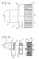
- the inhalation device shown in Figures 1a and 1b includes a housing 1 consisting in particular of a circular cup 10 axis B carrying a socket 11 axis A and a cover 2 cylindrical closing the housing 1 by fitting rotating around the axis B on the cup 10.
- the connector 11 has a conduit internal exhaust 11a diverging and closable by a pivoting valve 5.
- the cover 2 comprises at least one peripheral lug 20 of retainer slidably engaged in an interrupted groove 12 formed around the periphery of the cup 10 of the housing 1.
- the tenon 20 abuts against the ends of the groove 12 to limit the rotational travel of the cover 2 relative to the housing 1.
- the cover 2 further comprises an air intake orifice 21 (see Figure 2) located, in the inhalation position, in the extension of the axis A of the socket 11.
- the air intake port is fitted with a protective grid 24.
- the side face of the cover 2 is provided with grooves 22 facilitating the taking.
- the housing 1 and the cover 2 contain support means and transfer of the powdered product capsules.
- these means are consist of a magazine 3 in the form of a rotary barrel around the axis central B which is housed in the cup 10 and is provided with at least two cells 30 each intended to receive a G capsule containing a dose of medication.
- the length of the cells 30 is slightly less than the length of the capsules.
- the barrel has seven cells 30 arranged in a arc of a circle and is mounted on a hub 14 produced on the internal face of the cup 10.
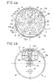
- the barrel 3 comprises, in addition, at least two pawls peripherals 31 and, as shown in FIGS. 3a and 4a, of preferably seven pawls 31 corresponding to the cells 30.
- the pawls 31 are intended to cooperate with cleats 13,23 formed on the periphery of the housing 1 and / or of the cover 2 to prevent any rotation of the barrel 3 in a direction opposite to that of the arrow F thereby forming a non-return system.
- the cooperation between the pawls 31 of the barrel 3 and the cleats 13,23 allows, by driving the cover 2 in rotation, an angular displacement, step by step and one-way, of the barrel 3 in the case 1.
- the barrel 3 and the cover 2 are connected functionally by a freewheel drive system authorizing a return back with respect to the arrow F, towards its position initial cover 2 after locking the barrel 3. This arrangement thus allows the air intake orifice 21 to be brought back into the extension of the axis A of the socket 11 for inhalation.
- This angular displacement defines as many stop positions of the barrel 3 that there are pawls 31 and leads to immobilize successively each cell 30 with its capsule G, longitudinally in the inhalation position, i.e. in the axis A of the intake nozzle 11.
- the barrel 3 is locked in the inhalation position thanks to the specific profiles of the pawls 31 and the cleats 13,23.
- the pawls 31 consist of legs 31a extending substantially tangentially to the periphery of the barrel 3 and which are likely to flex elastically towards the central axis B, at contact cleats 13,23 to retract. Legs 31a extend forward, in the direction of arrow F, by bent edges 31b. The free end of the legs 31a is located on the radius of the barrel 3 passing through the center of the corresponding cell 30.
- the cleats 13,23 consist of lugs of triangular section protruding towards the B axis.
- the front side face 13a, 23a of the cleats 13,23 in the direction of the feed F forms a stop for the free end of the tab 31a while their rear lateral face 13b, 23b comes into bearing contact, during the rotation of the barrel 3, first with the bent edges 31b of the pawls 31 then with the legs 31a.
- the junction between the front face 13a, 23a and the rear face 13b, 23b of the cleats forms an elbow of approximately 90 °.
- the cleats 13,23 are diametrically offset forever cooperate with two different pawls 31.
- the rear face 13b, 23b of cleats extends in the straight extension of the legs 31a when these are in abutment against the front face 13a, 23a of the cleats.
- the length of the groove 12 of the cup 10 of the housing in which slides the pin 20 for retaining the cover 2 corresponds therefore substantially at the angular distance separating two cells 30 or two legs 31a of the barrel 3.
- the tenon travel corresponds to an angular displacement of approximately 60 °.
- the housing 1 and the cover 2 also contain means opening capsules G.
- these means are consisting of two parallel blades 41,42 respectively secured to the case 1 and cover 2.
- the blades 41, 42 are adapted to cut each, one of the longitudinal ends of a capsule G by successive rotations relative to the housing 1 first in a first direction F, of the cover 2 driving the barrel 3 then the cover 2 alone, in reverse after locking said barrel in the inhalation position.
- Blades 41.42 are preferably identical and symmetrically arranged on one side and other of the cells 30. They have a central orifice 41a, 42a of which the diameter is slightly greater than that of G capsules for allow the evacuation of the product.
- the respective axes of the orifices 41a, 42a of the blades 41.42 are likely to coincide with each other and with the common axis A of the intake connector 11 and of the air intake orifice 21, in position inhalation.
- the cutting edges 41b, 42b of the blades 41,42 are arranged so as to cut the capsules G in turn tangentially to their cylindrical side wall, flush with the edge of the alveoli.
- a channel is thus open between the intake orifice 21 and the exhaust duct 11a at the inlet of the end fitting 11 which will allow seems to sweep the powder directly when the patient sucks in the mouthpiece.
- the cup 10 of the housing 1 has on its front face, a light 15 forming an indicator arranged opposite one stop positions of the cells 30 of the barrel 3 to control its filling level.
Landscapes
- Health & Medical Sciences (AREA)
- Engineering & Computer Science (AREA)
- Life Sciences & Earth Sciences (AREA)
- Animal Behavior & Ethology (AREA)
- Anesthesiology (AREA)
- Biomedical Technology (AREA)
- Heart & Thoracic Surgery (AREA)
- Hematology (AREA)
- Bioinformatics & Cheminformatics (AREA)
- Pulmonology (AREA)
- General Health & Medical Sciences (AREA)
- Public Health (AREA)
- Veterinary Medicine (AREA)
- Medical Preparation Storing Or Oral Administration Devices (AREA)
- Medicinal Preparation (AREA)
- Acyclic And Carbocyclic Compounds In Medicinal Compositions (AREA)
- External Artificial Organs (AREA)
Description
- les figures 1a et 1b représentent des vues extérieures d'ensemble du dispositif de l'invention respectivement assemblé et démonté ;
- la figure 2 représente une vue en coupe longitudinale selon la ligne I-I du dispositif de l'invention ;
- les figures 3a et 3b représentent des vues en coupe transversale selon III-III du dispositif de la figure 2 respectivement avec et sans le chargeur ; et,
- les figures 4a et 4b représentent des vues en coupe transversale selon IV-IV du dispositif de la figure 2 respectivement avec et sans le chargeur.
Claims (18)
- Dispositif pour l'inhalation de produits en poudres conditionnés en gélules (G) du type comprenant un boítier (1) obturé par un couvercle (2) et renfermant des moyens de support et de transfert des gélules (G), des moyens d'ouverture à deux lames desdites gélules (G), un embout de prise (11) et un orifice d'admission d'air (21), dont
lesdits moyens de support et de transfert des gélules sont constitués d'un chargeur mobile (3), pourvu d'au moins deux alvéoles (30) destinées à recevoir chacune une gélule (G) et de moyens anti-retour permettant d'obtenir par entraínement du couvercle (2), un déplacement pas à pas, à sens unique, du chargeur (3) dans le boítier (1) et caractérisé en ce que ledit chargeur (3) et les moyens anti-retour permettent d'immobiliser successivement chaque alvéole (30) dans une position d'inhalation où sa gélule (G) communique avec l'embout de prise (11) et en ce que lesdits moyens d'ouverture sont constitués de deux lames parallèles (41,42) respectivement solidaires du boítier (1) et du couvercle (2) adaptées pour couper chacune une des extrémités longitudinales d'une gélule (G) par déplacements successifs, relativement au boítier (1), d'abord du couvercle (2) entraínant le chargeur (3) dans un premier sens (F), puis du couvercle (2) seul, en sens inverse, après verrouillage du chargeur (3) en position d'inhalation. - Dispositif selon la revendication 1, caractérisé en ce que ledit chargeur mobile (3) est un barillet rotatif autour d'un axe central (B).
- Dispositif selon la revendication 1 ou 2, caractérisé en ce que lesdits moyens anti-retour sont constitués d'au moins deux cliquets (31) destinés à coopérer avec des taquets (13,23) ménagés sur le pourtour du boítier (1) et/ou du couvercle (2).
- Dispositif selon l'une des revendications précédentes,
caractérisé en ce que les lames (41,42) du boítier (1) et du couvercle (2) sont disposées de part et d'autre des alvéoles (30) et comportent un orifice central (41a,42a) dont le diamètre est légèrement supérieur à celui des gélules (G) et qui communique avec l'embout de prise (11) et l'orifice d'admission d'air (21) en position d'inhalation. - Dispositif selon la revendication 2,
caractérisé en ce que le couvercle (2) du boítier (1) est cylindrique et a un axe de rotation confondu avec l'axe central (B) du chargeur (3). - Dispositif selon l'une des revendications précédentes,
caractérisé en ce que le chargeur (3) et le couvercle (2) sont reliés par un système d'entraínement à roue libre. - Dispositif selon l'une des revendications précédentes, caractérisé en ce que ledit couvercle (2) comporte au moins un tenon périphérique (20) engagé de manière coulissante dans une rainure interrompue (12) ménagée sur le pourtour du boítier (1) et contre les extrémités de laquelle le tenon (20) vient en butée pour limiter la course dudit couvercle (2) par rapport audit boítier (1).
- Dispositif selon l'une des revendications précédentes, caractérisé en ce que l'embout de prise (11) comporte un conduit interne d'échappement (11a) divergent et obturable par un clapet (5).
- Dispositif selon la revendication 3, caractérisé en ce que lesdits cliquets (31) du chargeur (3) sont constitués de pattes (31a) s'étendant de façon sensiblement tangentielle à la périphérie du chargeur (3) et qui sont susceptibles de fléchir élastiquement au contact des taquets (13,23) pour s'escamoter.
- Dispositif selon les revendications 3 et 9,
caractérisé en ce que l'extrémité libre des pattes (31a) des cliquets (31) est située sur le rayon du barillet (3) passant par le centre d'une alvéole (30). - Dispositif selon la revendication 7,
caractérisé en ce que la longueur de la rainure périphérique (12) du boítier (1) correspond à la distance séparant deux alvéoles (30) du chargeur (3). - Dispositif selon l'une des revendications précédentes, caractérisé en ce que ledit orifice d'admission d'air (21) est ménagé au travers du couvercle (2) et est pourvu d'une grille protectrice (24).
- Dispositif selon l'une des revendications précédentes, caractérisé en ce que le boítier (1) comporte une coupelle (10) dans laquelle est logé le chargeur (3).
- Dispositif selon les revendications 2 et 13, caractérisé en ce que l'axe de ladite coupelle coïncide avec l'axe central (B) de rotation du barillet (3).
- Dispositif selon l'une des revendications précédentes, caractérisé en ce que ledit boítier (1) comporte une lumière (15) disposée en regard de l'une des positions d'arrêt des alvéoles (30) du chargeur (3) pour former un voyant de contrôle du remplissage dudit chargeur.
- Dispositif selon l'une des revendications précédentes, caractérisé en ce que la longueur des alvéoles (30) du chargeur (3) est inférieure à la longueur des gélules (G).
- Dispositif selon l'une des revendications précédentes, caractérisé en ce que les bords tranchants (41b,42b) des lames (41,42) du boítier (1) et du couvercle (2) sont disposés de façon à venir découper les gélules (G) tangentiellement à leur paroi latérale cylindrique.
- Dispositif selon les revendications 2 et 3, caractérisé en ce que le chargeur (3) comporte sept alvéoles (30) disposées selon un cercle et sept cliquets périphériques (31) correspondants.
Applications Claiming Priority (2)
| Application Number | Priority Date | Filing Date | Title |
|---|---|---|---|
| FR9412399A FR2725626A1 (fr) | 1994-10-18 | 1994-10-18 | Dispositif pour l'inhalation de produits en poudre |
| FR9412399 | 1994-10-18 |
Publications (2)
| Publication Number | Publication Date |
|---|---|
| EP0707862A1 EP0707862A1 (fr) | 1996-04-24 |
| EP0707862B1 true EP0707862B1 (fr) | 2001-06-27 |
Family
ID=9467948
Family Applications (1)
| Application Number | Title | Priority Date | Filing Date |
|---|---|---|---|
| EP95402283A Expired - Lifetime EP0707862B1 (fr) | 1994-10-18 | 1995-10-13 | Dispositif pour l'inhalation de produits en poudre |
Country Status (11)
| Country | Link |
|---|---|
| US (1) | US5651359A (fr) |
| EP (1) | EP0707862B1 (fr) |
| JP (1) | JPH08224309A (fr) |
| AT (1) | ATE202492T1 (fr) |
| CA (1) | CA2160602A1 (fr) |
| DE (1) | DE69521472T2 (fr) |
| DK (1) | DK0707862T3 (fr) |
| ES (1) | ES2160678T3 (fr) |
| FR (1) | FR2725626A1 (fr) |
| GR (1) | GR3036690T3 (fr) |
| PT (1) | PT707862E (fr) |
Cited By (1)
| Publication number | Priority date | Publication date | Assignee | Title |
|---|---|---|---|---|
| US9179691B2 (en) | 2007-12-14 | 2015-11-10 | Aerodesigns, Inc. | Delivering aerosolizable food products |
Families Citing this family (53)
| Publication number | Priority date | Publication date | Assignee | Title |
|---|---|---|---|---|
| US6470884B2 (en) | 1996-01-29 | 2002-10-29 | Aventis Pharma Limited | Capsule opening arrangement for use in a powder inhaler |
| SE9600306D0 (sv) * | 1996-01-29 | 1996-01-29 | Ernst Hoerlin | Capsule opening arrangement for use in a powder inhaler |
| US6309373B1 (en) * | 1998-08-12 | 2001-10-30 | Abbott Laboratories | Apparatus for altering the characteristics of a fluid |
| US9006175B2 (en) | 1999-06-29 | 2015-04-14 | Mannkind Corporation | Potentiation of glucose elimination |
| US7464706B2 (en) * | 1999-07-23 | 2008-12-16 | Mannkind Corporation | Unit dose cartridge and dry powder inhaler |
| WO2002013897A2 (fr) | 2000-08-14 | 2002-02-21 | Advanced Inhalation Research, Inc. | Inhalateur et procede correspondant |
| DE60101451T2 (de) * | 2001-03-05 | 2004-10-21 | Pera Ivo E | Inhaliergerät zur Verteilung von in einer Kapsel enthaltenen Medikamenten in Pulverform durch die Atemwege |
| US6766799B2 (en) * | 2001-04-16 | 2004-07-27 | Advanced Inhalation Research, Inc. | Inhalation device |
| EP1494732B1 (fr) * | 2002-03-20 | 2008-01-30 | MannKind Corporation | Appareil d'inhalation |
| ITMO20020297A1 (it) * | 2002-10-16 | 2004-04-17 | Roberto Oliva | Inalatore per preparati monodose in capsule. |
| JP4471929B2 (ja) * | 2003-10-09 | 2010-06-02 | 株式会社新日本科学 | 鼻腔用粉状薬剤施薬装置 |
| DK1786784T3 (da) | 2004-08-20 | 2011-02-14 | Mannkind Corp | Katalyse af diketopiperazinsyntese |
| CN104436170B (zh) | 2004-08-23 | 2018-02-23 | 曼金德公司 | 用于药物输送的二酮哌嗪盐 |
| AU2006290227B2 (en) | 2005-09-14 | 2012-08-02 | Mannkind Corporation | Method of drug formulation based on increasing the affinity of crystalline microparticle surfaces for active agents |
| DE102006006647B3 (de) * | 2006-02-14 | 2007-01-18 | Braunform Gmbh | Vorrichtung zum Inhalieren eines in einer Kapsel sich befindenden Pulvers |
| KR20080096809A (ko) | 2006-02-22 | 2008-11-03 | 맨카인드 코포레이션 | 디케토피페라진 및 활성제를 포함하는 마이크로입자의 약학특성의 개선 방법 |
| JP5188991B2 (ja) * | 2006-03-03 | 2013-04-24 | エスティーシー.ユーエヌエム | 空力弾性分配メカニズムを有するドライパウダー吸入器 |
| PT103481B (pt) * | 2006-05-16 | 2008-08-01 | Hovione Farmaciencia S A | Inalador de uso simples e método de inalação |
| US7806117B2 (en) * | 2006-06-07 | 2010-10-05 | Shin Nippon Biomedical Laboratories, Ltd. | Peroral powder delivery device |
| WO2008156586A2 (fr) * | 2007-06-12 | 2008-12-24 | Alkermes, Inc. | Perfectionnements à des dispositifs inhalateurs de poudre |
| US8485180B2 (en) | 2008-06-13 | 2013-07-16 | Mannkind Corporation | Dry powder drug delivery system |
| SG10201507036TA (en) | 2008-06-13 | 2015-10-29 | Mannkind Corp | A dry powder inhaler and system for drug delivery |
| EP2609954B1 (fr) | 2008-06-20 | 2021-12-29 | MannKind Corporation | Appareil interactif pour l'établissement en temps réel d'un profil des efforts d'inhalation |
| TWI614024B (zh) | 2008-08-11 | 2018-02-11 | 曼凱公司 | 超快起作用胰島素之用途 |
| US8314106B2 (en) | 2008-12-29 | 2012-11-20 | Mannkind Corporation | Substituted diketopiperazine analogs for use as drug delivery agents |
| MX2011009512A (es) | 2009-03-11 | 2011-11-29 | Mannkind Corp | Aparato, sistema y metodo para medir la resistencia de un inhalador. |
| MY157166A (en) | 2009-06-12 | 2016-05-13 | Mankind Corp | Diketopiperazine microparticles with defined specific surface areas |
| DE102009037840B4 (de) | 2009-08-18 | 2012-08-16 | Gamptec Gmbh | Inhalationsvorrichtung und Verfahren zur Inhalation eines Wirkstoffs aus einer Kapsel |
| CA2778698A1 (fr) | 2009-11-03 | 2011-05-12 | Mannkind Corporation | Appareil et methode de simulation d'efforts d'inhalation |
| CA2779488A1 (fr) | 2009-11-12 | 2011-05-19 | Stc.Unm | Inhalateur pour poudre seche avec un element de dispersion par flottement |
| IL223742A (en) | 2010-06-21 | 2016-06-30 | Mannkind Corp | A dry powder inhaler and preparation for it |
| JP6050758B2 (ja) | 2010-12-07 | 2016-12-21 | レスピラ セラピューティクス インコーポレイテッドRespira Therapeutics,Inc. | 乾燥粉末吸入器及びその作動方法 |
| EP2694402B1 (fr) | 2011-04-01 | 2017-03-22 | MannKind Corporation | Emballage coque pour cartouches pharmaceutiques |
| WO2012174472A1 (fr) | 2011-06-17 | 2012-12-20 | Mannkind Corporation | Microparticules de dicétopipérazine de capacité élevée |
| PT105961B (pt) * | 2011-10-24 | 2013-09-20 | Neutroplast Ind De Embalagens Plasticas S A | Inalador |
| HK1200318A1 (en) | 2011-10-24 | 2015-08-07 | 曼金德公司 | Methods and compositions for treating pain |
| US9603906B2 (en) | 2012-02-01 | 2017-03-28 | Protalix Ltd. | Inhalable liquid formulations of DNase I |
| US10463815B2 (en) | 2012-02-21 | 2019-11-05 | Respira Therapeutics, Inc. | Inhaler to deliver substances for prophylaxis or prevention of disease or injury caused by the inhalation of biological or chemical agents |
| EP3421042B1 (fr) | 2012-03-07 | 2024-04-17 | Beyond Air Ltd | Inhalation d'oxyde nitrique pour traiter des maladies des voies respiratoires |
| EP2872205B1 (fr) | 2012-07-12 | 2017-02-08 | MannKind Corporation | Systèmes de libération de médicament en poudre sèche |
| US10159644B2 (en) | 2012-10-26 | 2018-12-25 | Mannkind Corporation | Inhalable vaccine compositions and methods |
| WO2014144895A1 (fr) | 2013-03-15 | 2014-09-18 | Mannkind Corporation | Compositions de dicétopipérazine microcristallines et procédés |
| KR102465025B1 (ko) | 2013-07-18 | 2022-11-09 | 맨카인드 코포레이션 | 열-안정성 건조 분말 약제학적 조성물 및 방법 |
| EP3030294B1 (fr) | 2013-08-05 | 2020-10-07 | MannKind Corporation | Appareil d'insufflation |
| US10307464B2 (en) | 2014-03-28 | 2019-06-04 | Mannkind Corporation | Use of ultrarapid acting insulin |
| US10561806B2 (en) | 2014-10-02 | 2020-02-18 | Mannkind Corporation | Mouthpiece cover for an inhaler |
| WO2016057693A1 (fr) | 2014-10-10 | 2016-04-14 | Alnylam Pharmaceuticals, Inc. | Procédés et compositions pour administration par inhalation d'oligonucléotide conjugué |
| CN107427650A (zh) | 2015-01-14 | 2017-12-01 | 瑞必治公司 | 粉末分散方法和装置 |
| CN106031810A (zh) * | 2015-03-13 | 2016-10-19 | 丁要武 | 吸粉器及连接于该吸粉器的吸粉器本体上的药匣组件 |
| CN114072136B (zh) | 2019-04-29 | 2024-11-29 | 英斯梅德股份有限公司 | 曲前列素前药的干粉组合物及其使用方法 |
| EP4236934A4 (fr) | 2020-10-28 | 2024-10-02 | Insmed Incorporated | Compositions de poudre sèche de promédicaments de tréprostinil et procédés d'utilisation associés |
| WO2023150747A1 (fr) | 2022-02-07 | 2023-08-10 | Insmed Incorporated | Compositions de poudre sèche de bédaquiline et de sels et leurs méthodes d'utilisation |
| JP7592344B1 (ja) * | 2024-03-19 | 2024-12-02 | 森田通商株式会社 | 吸引具 |
Family Cites Families (11)
| Publication number | Priority date | Publication date | Assignee | Title |
|---|---|---|---|---|
| AU545574B2 (en) * | 1979-10-30 | 1985-07-18 | Riker Laboratories, Inc. | Breath actuated devices for adminstering powdered medicaments |
| NL192564C (nl) * | 1982-10-08 | 1997-10-03 | Glaxo Group Ltd | Inrichting voor het toedienen van medicamenten aan patiënten. |
| EP0211595B1 (fr) * | 1985-07-30 | 1991-11-13 | Glaxo Group Limited | Appareil pour administrer des médicaments à un patient |
| CH676796A5 (fr) * | 1987-09-09 | 1991-03-15 | Henri Dr Med Siegenthaler | |
| IT1230313B (it) * | 1989-07-07 | 1991-10-18 | Somova Spa | Inalatore per medicamenti in capsule. |
| DE3927170A1 (de) * | 1989-08-17 | 1991-02-21 | Boehringer Ingelheim Kg | Inhalator |
| GB9012870D0 (en) * | 1990-06-08 | 1990-08-01 | Glaxo Group Ltd | Device |
| US5492112A (en) * | 1991-05-20 | 1996-02-20 | Dura Pharmaceuticals, Inc. | Dry powder inhaler |
| GB2270293A (en) * | 1992-09-05 | 1994-03-09 | Medix Ltd | Drug dispensing system |
| CA2157584C (fr) * | 1993-03-03 | 1999-05-04 | Paul Mulhauser | Inhalateur pour medicament en poudre seche |
| US5533502A (en) * | 1993-05-28 | 1996-07-09 | Vortran Medical Technology, Inc. | Powder inhaler with aerosolization occurring within each individual powder receptacle |
-
1994
- 1994-10-18 FR FR9412399A patent/FR2725626A1/fr active Granted
-
1995
- 1995-10-13 EP EP95402283A patent/EP0707862B1/fr not_active Expired - Lifetime
- 1995-10-13 ES ES95402283T patent/ES2160678T3/es not_active Expired - Lifetime
- 1995-10-13 AT AT95402283T patent/ATE202492T1/de not_active IP Right Cessation
- 1995-10-13 DK DK95402283T patent/DK0707862T3/da active
- 1995-10-13 DE DE69521472T patent/DE69521472T2/de not_active Expired - Fee Related
- 1995-10-13 PT PT95402283T patent/PT707862E/pt unknown
- 1995-10-16 CA CA002160602A patent/CA2160602A1/fr not_active Abandoned
- 1995-10-17 US US08/544,017 patent/US5651359A/en not_active Expired - Fee Related
- 1995-10-18 JP JP7270017A patent/JPH08224309A/ja active Pending
-
2001
- 2001-09-20 GR GR20010401547T patent/GR3036690T3/el not_active IP Right Cessation
Cited By (1)
| Publication number | Priority date | Publication date | Assignee | Title |
|---|---|---|---|---|
| US9179691B2 (en) | 2007-12-14 | 2015-11-10 | Aerodesigns, Inc. | Delivering aerosolizable food products |
Also Published As
| Publication number | Publication date |
|---|---|
| EP0707862A1 (fr) | 1996-04-24 |
| FR2725626A1 (fr) | 1996-04-19 |
| DK0707862T3 (da) | 2001-09-03 |
| GR3036690T3 (en) | 2001-12-31 |
| PT707862E (pt) | 2001-12-28 |
| ATE202492T1 (de) | 2001-07-15 |
| CA2160602A1 (fr) | 1996-04-19 |
| DE69521472D1 (de) | 2001-08-02 |
| FR2725626B1 (fr) | 1997-02-21 |
| US5651359A (en) | 1997-07-29 |
| ES2160678T3 (es) | 2001-11-16 |
| DE69521472T2 (de) | 2002-04-18 |
| JPH08224309A (ja) | 1996-09-03 |
Similar Documents
| Publication | Publication Date | Title |
|---|---|---|
| EP0707862A1 (fr) | Dispositif pour l'inhalation de produits en poudre | |
| EP0900100B1 (fr) | Inhalateur a poudre et a air comprime | |
| EP2133110B1 (fr) | Dispositif de distribution de produit fluide | |
| WO1992005823A1 (fr) | Inhalateur a poudre | |
| EP2481432B1 (fr) | Dispositif de distribution de produit fluide | |
| EP0764312A1 (fr) | Compteur de doses pour inhalateurs | |
| EP2106269A2 (fr) | Dispositif de distribution de produit fluide | |
| EP2101849A2 (fr) | Dispositif de distribution de produit fluide | |
| EP2854913B1 (fr) | Dispositif de distribution de produit fluide | |
| WO2012004518A1 (fr) | Inhalateur de poudre seche | |
| WO2010004229A1 (fr) | Dispositif d'inhalation de poudre | |
| WO2006079747A1 (fr) | Dispositif de distribution de produit fluide | |
| WO2006079749A2 (fr) | Dispositif de distribution de produit fluide. | |
| EP2590700A2 (fr) | Inhalateur unidose de poudre seche pour blister pelable | |
| EP2440272A1 (fr) | Dispositif d'inhalation de poudre | |
| WO2006054021A2 (fr) | Dispositif de distribution de produit fluide | |
| FR2667790A1 (fr) | Cassette de conditionnement de microdoses de poudre sous forme de bandes adaptees a etre utilisees dans un inhalateur a poudre, et son procede de fabrication. | |
| WO2010004223A1 (fr) | Dispositif d'inhalation de poudre | |
| EP2364173A1 (fr) | Dispositif d'inhalation de poudre | |
| WO2008087311A2 (fr) | Dispositif de distribution de produit fluide | |
| FR2909642A1 (fr) | Dispositif de distribution de produit fluide |
Legal Events
| Date | Code | Title | Description |
|---|---|---|---|
| PUAI | Public reference made under article 153(3) epc to a published international application that has entered the european phase |
Free format text: ORIGINAL CODE: 0009012 |
|
| AK | Designated contracting states |
Kind code of ref document: A1 Designated state(s): AT BE CH DE DK ES FR GB GR IE IT LI LU MC NL PT SE |
|
| AX | Request for extension of the european patent |
Free format text: LT PAYMENT 951021;LV PAYMENT 951021;SI PAYMENT 951021 |
|
| RAX | Requested extension states of the european patent have changed |
Free format text: LT PAYMENT 951021;LV PAYMENT 951021;SI PAYMENT 951021 |
|
| 17P | Request for examination filed |
Effective date: 19960902 |
|
| RAP1 | Party data changed (applicant data changed or rights of an application transferred) |
Owner name: REXAM SOFAB |
|
| GRAG | Despatch of communication of intention to grant |
Free format text: ORIGINAL CODE: EPIDOS AGRA |
|
| GRAG | Despatch of communication of intention to grant |
Free format text: ORIGINAL CODE: EPIDOS AGRA |
|
| GRAH | Despatch of communication of intention to grant a patent |
Free format text: ORIGINAL CODE: EPIDOS IGRA |
|
| 17Q | First examination report despatched |
Effective date: 20001117 |
|
| GRAH | Despatch of communication of intention to grant a patent |
Free format text: ORIGINAL CODE: EPIDOS IGRA |
|
| GRAA | (expected) grant |
Free format text: ORIGINAL CODE: 0009210 |
|
| AK | Designated contracting states |
Kind code of ref document: B1 Designated state(s): AT BE CH DE DK ES FR GB GR IE IT LI LU MC NL PT SE |
|
| AX | Request for extension of the european patent |
Free format text: LT PAYMENT 19951021;LV PAYMENT 19951021;SI PAYMENT 19951021 |
|
| LTIE | Lt: invalidation of european patent or patent extension | ||
| REF | Corresponds to: |
Ref document number: 202492 Country of ref document: AT Date of ref document: 20010715 Kind code of ref document: T |
|
| REG | Reference to a national code |
Ref country code: CH Ref legal event code: EP |
|
| ITF | It: translation for a ep patent filed | ||
| REG | Reference to a national code |
Ref country code: IE Ref legal event code: FG4D Free format text: FRENCH |
|
| REG | Reference to a national code |
Ref country code: CH Ref legal event code: NV Representative=s name: BOVARD AG PATENTANWAELTE |
|
| REF | Corresponds to: |
Ref document number: 69521472 Country of ref document: DE Date of ref document: 20010802 |
|
| REG | Reference to a national code |
Ref country code: DK Ref legal event code: T3 |
|
| GBT | Gb: translation of ep patent filed (gb section 77(6)(a)/1977) |
Effective date: 20010824 |
|
| REG | Reference to a national code |
Ref country code: ES Ref legal event code: FG2A Ref document number: 2160678 Country of ref document: ES Kind code of ref document: T3 |
|
| REG | Reference to a national code |
Ref country code: PT Ref legal event code: SC4A Free format text: AVAILABILITY OF NATIONAL TRANSLATION Effective date: 20010918 |
|
| REG | Reference to a national code |
Ref country code: GB Ref legal event code: IF02 |
|
| PLBE | No opposition filed within time limit |
Free format text: ORIGINAL CODE: 0009261 |
|
| STAA | Information on the status of an ep patent application or granted ep patent |
Free format text: STATUS: NO OPPOSITION FILED WITHIN TIME LIMIT |
|
| 26N | No opposition filed | ||
| PGFP | Annual fee paid to national office [announced via postgrant information from national office to epo] |
Ref country code: SE Payment date: 20020917 Year of fee payment: 8 Ref country code: MC Payment date: 20020917 Year of fee payment: 8 Ref country code: LU Payment date: 20020917 Year of fee payment: 8 |
|
| PGFP | Annual fee paid to national office [announced via postgrant information from national office to epo] |
Ref country code: AT Payment date: 20020918 Year of fee payment: 8 |
|
| PGFP | Annual fee paid to national office [announced via postgrant information from national office to epo] |
Ref country code: NL Payment date: 20020919 Year of fee payment: 8 Ref country code: DK Payment date: 20020919 Year of fee payment: 8 |
|
| PGFP | Annual fee paid to national office [announced via postgrant information from national office to epo] |
Ref country code: IE Payment date: 20020925 Year of fee payment: 8 |
|
| PGFP | Annual fee paid to national office [announced via postgrant information from national office to epo] |
Ref country code: GR Payment date: 20020927 Year of fee payment: 8 |
|
| PGFP | Annual fee paid to national office [announced via postgrant information from national office to epo] |
Ref country code: DE Payment date: 20021007 Year of fee payment: 8 |
|
| PGFP | Annual fee paid to national office [announced via postgrant information from national office to epo] |
Ref country code: GB Payment date: 20021008 Year of fee payment: 8 |
|
| PGFP | Annual fee paid to national office [announced via postgrant information from national office to epo] |
Ref country code: PT Payment date: 20021009 Year of fee payment: 8 |
|
| PGFP | Annual fee paid to national office [announced via postgrant information from national office to epo] |
Ref country code: ES Payment date: 20021011 Year of fee payment: 8 |
|
| PGFP | Annual fee paid to national office [announced via postgrant information from national office to epo] |
Ref country code: CH Payment date: 20021014 Year of fee payment: 8 |
|
| PGFP | Annual fee paid to national office [announced via postgrant information from national office to epo] |
Ref country code: BE Payment date: 20021118 Year of fee payment: 8 |
|
| PG25 | Lapsed in a contracting state [announced via postgrant information from national office to epo] |
Ref country code: LU Free format text: LAPSE BECAUSE OF NON-PAYMENT OF DUE FEES Effective date: 20031013 Ref country code: IE Free format text: LAPSE BECAUSE OF NON-PAYMENT OF DUE FEES Effective date: 20031013 Ref country code: GB Free format text: LAPSE BECAUSE OF NON-PAYMENT OF DUE FEES Effective date: 20031013 Ref country code: AT Free format text: LAPSE BECAUSE OF NON-PAYMENT OF DUE FEES Effective date: 20031013 |
|
| PG25 | Lapsed in a contracting state [announced via postgrant information from national office to epo] |
Ref country code: SE Free format text: LAPSE BECAUSE OF NON-PAYMENT OF DUE FEES Effective date: 20031014 Ref country code: ES Free format text: LAPSE BECAUSE OF NON-PAYMENT OF DUE FEES Effective date: 20031014 |
|
| PG25 | Lapsed in a contracting state [announced via postgrant information from national office to epo] |
Ref country code: MC Free format text: LAPSE BECAUSE OF NON-PAYMENT OF DUE FEES Effective date: 20031031 Ref country code: LI Free format text: LAPSE BECAUSE OF NON-PAYMENT OF DUE FEES Effective date: 20031031 Ref country code: CH Free format text: LAPSE BECAUSE OF NON-PAYMENT OF DUE FEES Effective date: 20031031 Ref country code: BE Free format text: LAPSE BECAUSE OF NON-PAYMENT OF DUE FEES Effective date: 20031031 |
|
| BERE | Be: lapsed |
Owner name: *REXAM SOFAB Effective date: 20031031 |
|
| PG25 | Lapsed in a contracting state [announced via postgrant information from national office to epo] |
Ref country code: PT Free format text: LAPSE BECAUSE OF NON-PAYMENT OF DUE FEES Effective date: 20040430 Ref country code: DK Free format text: LAPSE BECAUSE OF NON-PAYMENT OF DUE FEES Effective date: 20040430 |
|
| PG25 | Lapsed in a contracting state [announced via postgrant information from national office to epo] |
Ref country code: NL Free format text: LAPSE BECAUSE OF NON-PAYMENT OF DUE FEES Effective date: 20040501 Ref country code: DE Free format text: LAPSE BECAUSE OF NON-PAYMENT OF DUE FEES Effective date: 20040501 |
|
| PG25 | Lapsed in a contracting state [announced via postgrant information from national office to epo] |
Ref country code: GR Free format text: LAPSE BECAUSE OF NON-PAYMENT OF DUE FEES Effective date: 20040504 |
|
| EUG | Se: european patent has lapsed | ||
| GBPC | Gb: european patent ceased through non-payment of renewal fee |
Effective date: 20031013 |
|
| REG | Reference to a national code |
Ref country code: DK Ref legal event code: EBP |
|
| REG | Reference to a national code |
Ref country code: CH Ref legal event code: PL |
|
| NLV4 | Nl: lapsed or anulled due to non-payment of the annual fee |
Effective date: 20040501 |
|
| REG | Reference to a national code |
Ref country code: IE Ref legal event code: MM4A |
|
| REG | Reference to a national code |
Ref country code: PT Ref legal event code: MM4A Free format text: LAPSE DUE TO NON-PAYMENT OF FEES Effective date: 20040430 |
|
| PGFP | Annual fee paid to national office [announced via postgrant information from national office to epo] |
Ref country code: FR Payment date: 20041012 Year of fee payment: 10 |
|
| REG | Reference to a national code |
Ref country code: ES Ref legal event code: FD2A Effective date: 20031014 |
|
| PG25 | Lapsed in a contracting state [announced via postgrant information from national office to epo] |
Ref country code: IT Free format text: LAPSE BECAUSE OF NON-PAYMENT OF DUE FEES;WARNING: LAPSES OF ITALIAN PATENTS WITH EFFECTIVE DATE BEFORE 2007 MAY HAVE OCCURRED AT ANY TIME BEFORE 2007. THE CORRECT EFFECTIVE DATE MAY BE DIFFERENT FROM THE ONE RECORDED. Effective date: 20051013 |
|
| PG25 | Lapsed in a contracting state [announced via postgrant information from national office to epo] |
Ref country code: FR Free format text: LAPSE BECAUSE OF NON-PAYMENT OF DUE FEES Effective date: 20060630 |
|
| REG | Reference to a national code |
Ref country code: FR Ref legal event code: ST Effective date: 20060630 |