EP0707862B1 - Inhalation device for powdery substances - Google Patents
Inhalation device for powdery substances Download PDFInfo
- Publication number
- EP0707862B1 EP0707862B1 EP95402283A EP95402283A EP0707862B1 EP 0707862 B1 EP0707862 B1 EP 0707862B1 EP 95402283 A EP95402283 A EP 95402283A EP 95402283 A EP95402283 A EP 95402283A EP 0707862 B1 EP0707862 B1 EP 0707862B1
- Authority
- EP
- European Patent Office
- Prior art keywords
- charger
- housing
- cover
- capsules
- chambers
- Prior art date
- Legal status (The legal status is an assumption and is not a legal conclusion. Google has not performed a legal analysis and makes no representation as to the accuracy of the status listed.)
- Expired - Lifetime
Links
Images


Classifications
-
- A—HUMAN NECESSITIES
- A61—MEDICAL OR VETERINARY SCIENCE; HYGIENE
- A61M—DEVICES FOR INTRODUCING MEDIA INTO, OR ONTO, THE BODY; DEVICES FOR TRANSDUCING BODY MEDIA OR FOR TAKING MEDIA FROM THE BODY; DEVICES FOR PRODUCING OR ENDING SLEEP OR STUPOR
- A61M15/00—Inhalators
- A61M15/0028—Inhalators using prepacked dosages, one for each application, e.g. capsules to be perforated or broken-up
- A61M15/0045—Inhalators using prepacked dosages, one for each application, e.g. capsules to be perforated or broken-up using multiple prepacked dosages on a same carrier, e.g. blisters
-
- A—HUMAN NECESSITIES
- A61—MEDICAL OR VETERINARY SCIENCE; HYGIENE
- A61M—DEVICES FOR INTRODUCING MEDIA INTO, OR ONTO, THE BODY; DEVICES FOR TRANSDUCING BODY MEDIA OR FOR TAKING MEDIA FROM THE BODY; DEVICES FOR PRODUCING OR ENDING SLEEP OR STUPOR
- A61M15/00—Inhalators
- A61M15/0028—Inhalators using prepacked dosages, one for each application, e.g. capsules to be perforated or broken-up
- A61M15/003—Inhalators using prepacked dosages, one for each application, e.g. capsules to be perforated or broken-up using capsules, e.g. to be perforated or broken-up
- A61M15/0033—Details of the piercing or cutting means
- A61M15/0038—Cutting means
-
- A—HUMAN NECESSITIES
- A61—MEDICAL OR VETERINARY SCIENCE; HYGIENE
- A61M—DEVICES FOR INTRODUCING MEDIA INTO, OR ONTO, THE BODY; DEVICES FOR TRANSDUCING BODY MEDIA OR FOR TAKING MEDIA FROM THE BODY; DEVICES FOR PRODUCING OR ENDING SLEEP OR STUPOR
- A61M15/00—Inhalators
- A61M15/0028—Inhalators using prepacked dosages, one for each application, e.g. capsules to be perforated or broken-up
- A61M15/0045—Inhalators using prepacked dosages, one for each application, e.g. capsules to be perforated or broken-up using multiple prepacked dosages on a same carrier, e.g. blisters
- A61M15/0046—Inhalators using prepacked dosages, one for each application, e.g. capsules to be perforated or broken-up using multiple prepacked dosages on a same carrier, e.g. blisters characterized by the type of carrier
- A61M15/0048—Inhalators using prepacked dosages, one for each application, e.g. capsules to be perforated or broken-up using multiple prepacked dosages on a same carrier, e.g. blisters characterized by the type of carrier the dosages being arranged in a plane, e.g. on diskettes
-
- A—HUMAN NECESSITIES
- A61—MEDICAL OR VETERINARY SCIENCE; HYGIENE
- A61M—DEVICES FOR INTRODUCING MEDIA INTO, OR ONTO, THE BODY; DEVICES FOR TRANSDUCING BODY MEDIA OR FOR TAKING MEDIA FROM THE BODY; DEVICES FOR PRODUCING OR ENDING SLEEP OR STUPOR
- A61M2202/00—Special media to be introduced, removed or treated
- A61M2202/06—Solids
- A61M2202/064—Powder
Definitions
- the present invention relates to a device for the inhalation of powder products and, more particularly, powder products packaged in capsules.
- a device according to the preamble of claim 1 is known from EP-A-406893.
- the object of the present invention is to solve these problems techniques satisfactorily.
- a device for inhalation of powdered products packaged in capsules of the type comprising a housing closed by a cover and containing support and transfer means for capsules, opening means said capsules, an intake nozzle and an air intake orifice, of which said means for supporting and transferring capsules consist of a mobile charger, provided with at least two alveoli intended to each receive a capsule and non-return means allowing to obtain by training due cover a one-way, step-by-step movement of the charger into the housing and to successively immobilize each cell in a position inhalation where its capsule communicates with the socket and whose said opening means consist of two parallel blades respectively secured to the housing and the cover adapted for each cut one of the longitudinal ends of a capsule by successive movements relative to the housing first of the cover driving the charger in a first direction then the cover alone reverse after locking the charger in the inhalation position.
- said mobile charger is a barrel rotating around a central axis and said non-return means consist of at least two pawls intended to cooperate with cleats formed around the periphery of the housing and / or the cover.
- the cover of the case is cylindrical and has an axis of rotation confused with the central axis of the loader.
- the free end of the pawl tabs is located on the radius of the barrel passing through the center of a cell.
- the blades the housing and the cover are arranged on either side of the cells and have a central hole whose diameter is slightly superior to that of capsules and which communicates with the socket and the air intake port in the inhalation position.
- the charger is driven by the cover by preferably by means of a freewheel system.
- said cover includes at least one lug device slidably engaged in a groove interrupted formed around the periphery of the housing and against the ends of which the post abuts to limit the stroke of said cover with respect to said housing.
- the length of the peripheral groove of the case corresponds to the distance separating two cells from the charger.
- the pawls of the charger are made up of legs extending substantially tangentially to the periphery of the magazine and which are likely to flex elastically in contact with the cleats to retract.
- the plug end comprises a internal exhaust duct diverging and closable by a valve while said air intake orifice is formed through the cover and is provided with a protective grid.
- the housing comprises a cup in which the charger is housed.
- the axis of said cup coincides with the central axis of rotation of the barrel and is offset relative to the axis of the socket.
- the housing will include a light arranged in look at one of the charger cell stop positions for form a control lamp for filling said charger.
- the length of the cells of the magazine is less than the length of the capsules and the edges cutting edges of the housing and cover blades are arranged so that cut the capsules tangentially to their side wall cylindrical.
- the charger is a barrel which has seven cells arranged in a circle and seven corresponding peripheral pawls.
- the present invention provides an easy-to-use pocket device. use because prohibiting a double dosage and not requiring for inhalation, no precise coordination of inspiration with an order manual while protecting the user from expiration accidental.
- the housing is provided with a plug end such as a mouthpiece of oral suction and carries the mechanism allowing the distribution of product.
- This mechanism includes support and transfer means alternately bringing the capsules into the inhalation position by a step-by-step movement thanks to elastic-supported stop members deformable provided with non-return means to immobilize them therein look of an exhaust port towards the internal channel of the nozzle cited above; it will in principle be a mobile charger for example rotating like a barrel or capable of being moved so linear and guided in a rectilinear housing.
- the capsules will be there placed either individually or integrated into a package, advantageously interchangeable, such as a tape or a disc possibly forming the charger itself.
- the edges sharp blades will advantageously be oblique and their entry into offset action.
- a driving organ or coach in principle irreversible and manually controlled, will move the charger successively one stop position to the next.
- the use of a multiplied transmission such as worm or Maltese cross is not necessary; we him prefer the simple way of a free-wheeling system back and forth between two stops, in particular a blocked loader system alternative, first to go on a button-operated trainer same axis as him, then on the box on the return of this coach, possibly then helped by a spring: to secure the two organs, we can imagine ball ratchets here but we prefer the simple use of ratchets working in the same direction on two tracks parallel; if necessary the heels of the cutting blades themselves could fulfill this role.
- the two blades will then preferably be mounted respectively one on the case the other on the coach, the first acting during the advance movement by which it drives the charger, the second when it is brought back, alone, to its starting position.
- the two falls created by the opening of the capsule will advantageously discharged to an internal receptacle.
- the inhalation device shown in Figures 1a and 1b includes a housing 1 consisting in particular of a circular cup 10 axis B carrying a socket 11 axis A and a cover 2 cylindrical closing the housing 1 by fitting rotating around the axis B on the cup 10.
- the connector 11 has a conduit internal exhaust 11a diverging and closable by a pivoting valve 5.
- the cover 2 comprises at least one peripheral lug 20 of retainer slidably engaged in an interrupted groove 12 formed around the periphery of the cup 10 of the housing 1.
- the tenon 20 abuts against the ends of the groove 12 to limit the rotational travel of the cover 2 relative to the housing 1.
- the cover 2 further comprises an air intake orifice 21 (see Figure 2) located, in the inhalation position, in the extension of the axis A of the socket 11.
- the air intake port is fitted with a protective grid 24.
- the side face of the cover 2 is provided with grooves 22 facilitating the taking.
- the housing 1 and the cover 2 contain support means and transfer of the powdered product capsules.
- these means are consist of a magazine 3 in the form of a rotary barrel around the axis central B which is housed in the cup 10 and is provided with at least two cells 30 each intended to receive a G capsule containing a dose of medication.
- the length of the cells 30 is slightly less than the length of the capsules.
- the barrel has seven cells 30 arranged in a arc of a circle and is mounted on a hub 14 produced on the internal face of the cup 10.
- the barrel 3 comprises, in addition, at least two pawls peripherals 31 and, as shown in FIGS. 3a and 4a, of preferably seven pawls 31 corresponding to the cells 30.
- the pawls 31 are intended to cooperate with cleats 13,23 formed on the periphery of the housing 1 and / or of the cover 2 to prevent any rotation of the barrel 3 in a direction opposite to that of the arrow F thereby forming a non-return system.
- the cooperation between the pawls 31 of the barrel 3 and the cleats 13,23 allows, by driving the cover 2 in rotation, an angular displacement, step by step and one-way, of the barrel 3 in the case 1.
- the barrel 3 and the cover 2 are connected functionally by a freewheel drive system authorizing a return back with respect to the arrow F, towards its position initial cover 2 after locking the barrel 3. This arrangement thus allows the air intake orifice 21 to be brought back into the extension of the axis A of the socket 11 for inhalation.
- This angular displacement defines as many stop positions of the barrel 3 that there are pawls 31 and leads to immobilize successively each cell 30 with its capsule G, longitudinally in the inhalation position, i.e. in the axis A of the intake nozzle 11.
- the barrel 3 is locked in the inhalation position thanks to the specific profiles of the pawls 31 and the cleats 13,23.
- the pawls 31 consist of legs 31a extending substantially tangentially to the periphery of the barrel 3 and which are likely to flex elastically towards the central axis B, at contact cleats 13,23 to retract. Legs 31a extend forward, in the direction of arrow F, by bent edges 31b. The free end of the legs 31a is located on the radius of the barrel 3 passing through the center of the corresponding cell 30.
- the cleats 13,23 consist of lugs of triangular section protruding towards the B axis.
- the front side face 13a, 23a of the cleats 13,23 in the direction of the feed F forms a stop for the free end of the tab 31a while their rear lateral face 13b, 23b comes into bearing contact, during the rotation of the barrel 3, first with the bent edges 31b of the pawls 31 then with the legs 31a.
- the junction between the front face 13a, 23a and the rear face 13b, 23b of the cleats forms an elbow of approximately 90 °.
- the cleats 13,23 are diametrically offset forever cooperate with two different pawls 31.
- the rear face 13b, 23b of cleats extends in the straight extension of the legs 31a when these are in abutment against the front face 13a, 23a of the cleats.
- the length of the groove 12 of the cup 10 of the housing in which slides the pin 20 for retaining the cover 2 corresponds therefore substantially at the angular distance separating two cells 30 or two legs 31a of the barrel 3.
- the tenon travel corresponds to an angular displacement of approximately 60 °.
- the housing 1 and the cover 2 also contain means opening capsules G.
- these means are consisting of two parallel blades 41,42 respectively secured to the case 1 and cover 2.
- the blades 41, 42 are adapted to cut each, one of the longitudinal ends of a capsule G by successive rotations relative to the housing 1 first in a first direction F, of the cover 2 driving the barrel 3 then the cover 2 alone, in reverse after locking said barrel in the inhalation position.
- Blades 41.42 are preferably identical and symmetrically arranged on one side and other of the cells 30. They have a central orifice 41a, 42a of which the diameter is slightly greater than that of G capsules for allow the evacuation of the product.
- the respective axes of the orifices 41a, 42a of the blades 41.42 are likely to coincide with each other and with the common axis A of the intake connector 11 and of the air intake orifice 21, in position inhalation.
- the cutting edges 41b, 42b of the blades 41,42 are arranged so as to cut the capsules G in turn tangentially to their cylindrical side wall, flush with the edge of the alveoli.
- a channel is thus open between the intake orifice 21 and the exhaust duct 11a at the inlet of the end fitting 11 which will allow seems to sweep the powder directly when the patient sucks in the mouthpiece.
- the cup 10 of the housing 1 has on its front face, a light 15 forming an indicator arranged opposite one stop positions of the cells 30 of the barrel 3 to control its filling level.
Abstract
Description
La présente invention concerne un dispositif pour l'inhalation de produits en poudre et, plus particulièrement, de produits pulvérulents conditionnés en gélules.The present invention relates to a device for the inhalation of powder products and, more particularly, powder products packaged in capsules.
Divers produits, spécialement des médicaments, demandent à être mis en oeuvre et, en particulier, inhalés sous forme de poudres fines. Une difficulté est alors de concilier simplicité du dispositif, efficacité, en particulier précision et dispersion de la dose délivrée, sureté, en particulier hygiène et aseptie, etc. Il apparait donc intéressant a priori de conditionner ces produits en gélules uni doses qu'il conviendra d'ouvrir, par exemple en les découpant ou en les perforant avant d'entraíner leur contenu dans le courant d'air inhalé. Cette opération délicate a déjà été effectuée selon diverses et nombreuses manières : ainsi, pour expulser le produit, il a été proposé d'opérer par gravité ou centrifugation, mise en vibration ou en dépression, balayage direct par le courant principal ou le courant induit d'un venturi.Various products, especially drugs, require be used and, in particular, inhaled in the form of powders fine. A difficulty is then to reconcile simplicity of the device, effectiveness, in particular accuracy and dispersion of the dose delivered, safety, in particular hygiene and sanitation, etc. It therefore appears interesting a priori to package these products in single dose capsules that should be opened, for example by cutting or perforating them before entraining their content in the inhaled air stream. This delicate operation has already been carried out according to various and numerous manners: thus, to expel the product, it was proposed to operate by gravity or centrifugation, vibration or depression, scanning direct by the main current or the induced current of a venturi.
Un dispositif selon le préambule de la revendication 1 est connu de EP-A-406893.A device according to the preamble of
Mais les dispositifs antérieurs ne permettent pas de synchroniser rapidement la création ou l'émission du flux porteur de poudre avec l'inhalation. De plus, ces dispositifs doivent être rechargés fréquemment, ce qui rend leur utilisation laborieuse.But the previous devices do not allow synchronization quickly creation or emission of the powder-carrying flux with inhalation. In addition, these devices must be recharged frequently, which makes their use laborious.
La présente invention a pour but de résoudre ces problèmes techniques de manière satisfaisante.The object of the present invention is to solve these problems techniques satisfactorily.
Ce but est atteint selon l'invention au moyen d'un dispositif pour l'inhalation de produits en poudres conditionnés en gélules du type comprenant un boítier obturé par un couvercle et renfermant des moyens de support et de transfert des gélules, des moyens d'ouverture desdites gélules, un embout de prise et un orifice d'admission d'air, dont lesdits moyens de support et de transfert des gélules sont constitués d'un chargeur mobile, pourvu d'au moins deux alvéoles destinées à recevoir chacune une gélule et de moyens anti-retour permettant d'obtenir par entraínement dû couvercle un déplacement pas à pas, à sens unique, du chargeur dans le boítier et d'immobiliser successivement chaque alvéole dans une position d'inhalation où sa gélule communique avec l'embout de prise et dont lesdits moyens d'ouverture sont constitués de deux lames parallèles respectivement solidaires du boítier et du couvercle adaptées pour couper chacune une des extrémités longitudinales d'une gélule par déplacements successifs relativement au boítier d'abord du couvercle entraínant le chargeur dans un premier sens puis du couvercle seul en sens inverse après verrouillage du chargeur en position d'inhalation.This object is achieved according to the invention by means of a device for inhalation of powdered products packaged in capsules of the type comprising a housing closed by a cover and containing support and transfer means for capsules, opening means said capsules, an intake nozzle and an air intake orifice, of which said means for supporting and transferring capsules consist of a mobile charger, provided with at least two alveoli intended to each receive a capsule and non-return means allowing to obtain by training due cover a one-way, step-by-step movement of the charger into the housing and to successively immobilize each cell in a position inhalation where its capsule communicates with the socket and whose said opening means consist of two parallel blades respectively secured to the housing and the cover adapted for each cut one of the longitudinal ends of a capsule by successive movements relative to the housing first of the cover driving the charger in a first direction then the cover alone reverse after locking the charger in the inhalation position.
Selon un mode de réalisation avantageux, ledit chargeur mobile est un barillet rotatif autour d'un axe central et lesdits moyens anti-retour sont constitués d'au moins deux cliquets destinés à coopérer avec des taquets ménagés sur le pourtour du boítier et/ou du couvercle.According to an advantageous embodiment, said mobile charger is a barrel rotating around a central axis and said non-return means consist of at least two pawls intended to cooperate with cleats formed around the periphery of the housing and / or the cover.
De préférence, le couvercle du boítier est cylindrique et a un axe de rotation confondu avec l'axe central du chargeur.Preferably, the cover of the case is cylindrical and has an axis of rotation confused with the central axis of the loader.
Dans ce cas, l'extrémité libre des pattes des cliquets est située sur le rayon du barillet passant par le centre d'une alvéole.In this case, the free end of the pawl tabs is located on the radius of the barrel passing through the center of a cell.
Selon une caractéristique avantageuse de l'invention, les lames du boítier et du couvercle sont disposées de part et d'autre des alvéoles et comportent un orifice central dont le diamètre est légèrement supérieur à celui des gélules et qui communique avec l'embout de prise et l'orifice d'admission d'air en position d'inhalation.According to an advantageous characteristic of the invention, the blades the housing and the cover are arranged on either side of the cells and have a central hole whose diameter is slightly superior to that of capsules and which communicates with the socket and the air intake port in the inhalation position.
L'entraínement du chargeur par le couvercle s'effectue de préférence au moyen d'un système à roue libre.The charger is driven by the cover by preferably by means of a freewheel system.
De plus, ledit couvercle comporte au moins un tenon périphérique engagé de manière coulissante dans une rainure interrompue ménagée sur le pourtour du boítier et contre les extrémités de laquelle le tenon vient en butée pour limiter la course dudit couvercle par rapport audit boítier.In addition, said cover includes at least one lug device slidably engaged in a groove interrupted formed around the periphery of the housing and against the ends of which the post abuts to limit the stroke of said cover with respect to said housing.
La longueur de la rainure périphérique du boítier correspond à la distance séparant deux alvéoles du chargeur.The length of the peripheral groove of the case corresponds to the distance separating two cells from the charger.
Par ailleurs, il est prévu que les cliquets du chargeur sont constitués de pattes s'étendant de façon sensiblement tangentielle à la périphérie du chargeur et qui sont susceptibles de fléchir élastiquement au contact des taquets pour s'escamoter.In addition, it is expected that the pawls of the charger are made up of legs extending substantially tangentially to the periphery of the magazine and which are likely to flex elastically in contact with the cleats to retract.
Selon une autre caractéristique, l'embout de prise comporte un conduit interne d'échappement divergent et obturable par un clapet tandis que ledit orifice d'admission d'air est ménagé au travers du couvercle et est pourvu d'une grille protectrice.According to another characteristic, the plug end comprises a internal exhaust duct diverging and closable by a valve while said air intake orifice is formed through the cover and is provided with a protective grid.
Selon une première variante de réalisation, le boítier comporte une coupelle dans laquelle est logé le chargeur. According to a first alternative embodiment, the housing comprises a cup in which the charger is housed.
Lorsque le chargeur est un barillet rotatif, l'axe de ladite coupelle coïncide avec l'axe central de rotation du barillet et est décalé par rapport à l'axe de l'embout de prise.When the magazine is a rotating barrel, the axis of said cup coincides with the central axis of rotation of the barrel and is offset relative to the axis of the socket.
Eventuellement, le boítier comportera une lumière disposée en regard de l'une des positions d'arrêt des alvéoles du chargeur pour former un voyant de contrôle du remplissage dudit chargeur.Optionally, the housing will include a light arranged in look at one of the charger cell stop positions for form a control lamp for filling said charger.
Selon encore une autre caractéristique, la longueur des alvéoles du chargeur est inférieure à la longueur des gélules et les bords tranchants des lames du boítier et du couvercle sont disposés de façon à venir découper les gélules tangentiellement à leur paroi latérale cylindrique.According to yet another characteristic, the length of the cells of the magazine is less than the length of the capsules and the edges cutting edges of the housing and cover blades are arranged so that cut the capsules tangentially to their side wall cylindrical.
Selon une autre variante de réalisation, le chargeur est un barillet qui comporte sept alvéoles disposées selon un cercle et sept cliquets périphériques correspondants.According to another alternative embodiment, the charger is a barrel which has seven cells arranged in a circle and seven corresponding peripheral pawls.
La présente invention fournit un dispositif de poche facile à utiliser car interdisant un double dosage et n'exigeant pour l'inhalation, aucune coordination précise de l'inspiration avec une commande manuelle tout en protégeant l'utilisateur contre une expiration accidentelle.The present invention provides an easy-to-use pocket device. use because prohibiting a double dosage and not requiring for inhalation, no precise coordination of inspiration with an order manual while protecting the user from expiration accidental.
Le boítier est muni d'un embout de prise tel qu'un embout d'aspiration buccal et porte le mécanisme permettant la distribution du produit.The housing is provided with a plug end such as a mouthpiece of oral suction and carries the mechanism allowing the distribution of product.
Ce mécanisme comprend des moyens de support et de transfert amenant tour à tour les gélules en position d'inhalation par un mouvement pas à pas grâce à des organes d'arrêt à support élastique déformable pourvus de moyens anti-retour pour les y immobiliser en regard d'un orifice d'échappement vers le canal interne de l'embout précité ; il s'agira en principe d'un chargeur mobile par exemple tournant à la manière d'un barillet ou susceptible d'être déplacé de façon linéaire et guidée dans un logement rectiligne. Les gélules y seront placées soit individuellement soit intégrées à un conditionnement, avantageusement interchangeable, tel qu'une bande ou encore un disque formant éventuellement lui-même le chargeur.This mechanism includes support and transfer means alternately bringing the capsules into the inhalation position by a step-by-step movement thanks to elastic-supported stop members deformable provided with non-return means to immobilize them therein look of an exhaust port towards the internal channel of the nozzle cited above; it will in principle be a mobile charger for example rotating like a barrel or capable of being moved so linear and guided in a rectilinear housing. The capsules will be there placed either individually or integrated into a package, advantageously interchangeable, such as a tape or a disc possibly forming the charger itself.
Il comprend ensuite deux lames tranchantes dirigées dans le même sens le long de deux faces opposées du chargeur, à distance telle que leur mouvement relatif les amène à trancher les deux extrémités de toute gélule au moment de sa mise en place en position d'inhalation devant l'orifice d'échappement. Pour faciliter cette opération, les arêtes des lames tranchantes seront avantageusement obliques et leur entrée en action décalée.It then includes two sharp blades directed into the same direction along two opposite sides of the charger, at a distance such that their relative movement leads them to slice the two ends of any capsule when placed in the inhalation position in front of the exhaust port. To facilitate this operation, the edges sharp blades will advantageously be oblique and their entry into offset action.
Un organe d'entraínement ou entraíneur, en principe irréversible et à commande manuelle, déplacera successivement le chargeur d'une position d'arrêt à la suivante. L'emploi d'une transmission démultipliée telle que vis sans fin ou croix de Malte n'est pas nécessaire ; on lui préférera le moyen simple d'un système à roue libre en va-et-vient entre deux butées, en particulier un système à chargeur en blocage alternatif, d'abord à l'aller sur un entraíneur à bouton de manoeuvre de même axe que lui, ensuite sur le boítier au retour de cet entraíneur, éventuellement aidé alors par un ressort : pour solidariser les deux organes, on peut imaginer ici des rochets à bille mais on préférera le simple emploi de cliquets travaillant dans le même sens sur deux voies parallèles ; le cas échéant les talons des lames tranchantes elles-mêmes pourraient remplir ce rôle.A driving organ or coach, in principle irreversible and manually controlled, will move the charger successively one stop position to the next. The use of a multiplied transmission such as worm or Maltese cross is not necessary; we him prefer the simple way of a free-wheeling system back and forth between two stops, in particular a blocked loader system alternative, first to go on a button-operated trainer same axis as him, then on the box on the return of this coach, possibly then helped by a spring: to secure the two organs, we can imagine ball ratchets here but we prefer the simple use of ratchets working in the same direction on two tracks parallel; if necessary the heels of the cutting blades themselves could fulfill this role.
Les deux lames seront alors de préférence montées respectivement l'une sur le boítier l'autre sur l'entraíneur, la première agissant lors du mouvement d'avance par lequel celui-ci entraíne le chargeur, la seconde lorsqu'il est ramené, seul, à sa position de départ. Les deux chutes créées par l'ouverture de la gélule seront avantageusement évacuées vers un réceptacle interne.The two blades will then preferably be mounted respectively one on the case the other on the coach, the first acting during the advance movement by which it drives the charger, the second when it is brought back, alone, to its starting position. The two falls created by the opening of the capsule will advantageously discharged to an internal receptacle.
L'invention sera mieux comprise à la lecture de la description qui va suivre, d'un mode de réalisation particulier, accompagnée des dessins sur lesquels :
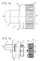
- les figures 1a et 1b représentent des vues extérieures d'ensemble du dispositif de l'invention respectivement assemblé et démonté ;
- la figure 2 représente une vue en coupe longitudinale selon la ligne I-I du dispositif de l'invention ;
- les figures 3a et 3b représentent des vues en coupe transversale selon III-III du dispositif de la figure 2 respectivement avec et sans le chargeur ; et,
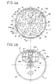
- les figures 4a et 4b représentent des vues en coupe transversale selon IV-IV du dispositif de la figure 2 respectivement avec et sans le chargeur.
- Figures 1a and 1b show overall exterior views of the device of the invention respectively assembled and disassembled;
- FIG. 2 represents a view in longitudinal section along line II of the device of the invention;
- Figures 3a and 3b show cross-sectional views along III-III of the device of Figure 2 respectively with and without the charger; and,
- Figures 4a and 4b show cross-sectional views along IV-IV of the device of Figure 2 respectively with and without the charger.
Le dispositif d'inhalation représenté sur les figures 1a et 1b
comprend un boítier 1 constitué notamment d'une coupelle circulaire 10
d'axe B portant un embout de prise 11 d'axe A et un couvercle 2
cylindrique venant obturer le boítier 1 en s'emboítant tournant autour de
l'axe B sur la coupelle 10. L'embout de prise 11 comporte un conduit
interne d'échappement 11a divergent et obturable par un clapet pivotant
5.The inhalation device shown in Figures 1a and 1b
includes a
Le couvercle 2 comporte au moins un tenon périphérique 20 de
retenue engagé de manière coulissante dans une rainure interrompue 12
ménagée sur le pourtour de la coupelle 10 du boítier 1. Le tenon 20
vient en butée contre les extrémités de la rainure 12 pour limiter la
course en rotation du couvercle 2 par rapport au boítier 1.The
Le couvercle 2 comporte en outre un orifice d'admission d'air 21
(voir figure 2) situé, en position d'inhalation, dans le prolongement de
l'axe A de l'embout de prise 11.The
L'orifice d'admission d'air est équipé d'une grille protectrice 24.The air intake port is fitted with a
La face latérale du couvercle 2 est munie de cannelures 22
facilitant la prise.The side face of the
Le boítier 1 et le couvercle 2 renferment des moyens de support
et de transfert des gélules de produit pulvérulent.The
Dans le mode de réalisation des figures 1b et 2 ces moyens sont
constitués d'un chargeur 3 sous forme d'un barillet rotatif autour de l'axe
central B qui est logé dans la coupelle 10 et est pourvu d'au moins deux
alvéoles 30 destinées à recevoir chacune une gélule G contenant une
dose de médicament. La longueur des alvéoles 30 est légèrement
inférieure à la longueur des gélules. Dans le mode de réalisation des
figures 3a et 4a, le barillet comporte sept alvéoles 30 disposées selon un
arc de cercle et est monté sur un moyeu 14 réalisé sur la face interne de
la coupelle 10.In the embodiment of Figures 1b and 2 these means are
consist of a
Le barillet 3 comporte, en outre, au moins deux cliquets
périphériques 31 et, comme représenté sur les figures 3a et 4a, de
préférence sept cliquets 31 correspondant aux alvéoles 30. The
Les cliquets 31 sont destinés à coopérer avec des taquets 13,23
ménagés sur le pourtour du boítier 1 et/ou du couvercle 2 pour interdire
toute rotation du barillet 3 dans un sens contraire à celui de la flèche F
en formant ainsi un système anti-retour.The
En d'autres termes, la coopération entre les cliquets 31 du
barillet 3 et les taquets 13,23 permet, par entraínement du couvercle 2
en rotation, un déplacement angulaire, pas à pas et à sens unique, du
barillet 3 dans le boítier 1. Le barillet 3 et le couvercle 2 sont reliés de
manière fonctionnelle par un système d'entraínement à roue libre
autorisant un retour en arrière par rapport à la flèche F, vers sa position
initiale du couvercle 2 après verrouillage du barillet 3. Cette disposition
permet ainsi de ramener l'orifice d'admission d'air 21 dans le
prolongement de l'axe A de l'embout de prise 11 pour l'inhalation.In other words, the cooperation between the
Ce déplacement angulaire définit autant de positions d'arrêt du
barillet 3 qu'il y a de cliquets 31 et conduit à immobiliser
successivement chaque alvéole 30 avec sa gélule G, longitudinalement
en position d'inhalation, c'est-à-dire dans l'axe A de l'embout de prise
11.This angular displacement defines as many stop positions of the
Le barillet 3 est verrouillé en position d'inhalation grâce aux
profils spécifiques des cliquets 31 et des taquets 13,23.The
En effet, les cliquets 31 sont constitués de pattes 31a s'étendant
de façon sensiblement tangentielle à la périphérie du barillet 3 et qui
sont susceptibles de fléchir élastiquement vers l'axe central B, au
contact des taquets 13,23 pour s'escamoter. Les pattes 31a se prolongent
vers l'avant, dans le sens de la flèche F, par des bords coudés 31b.
L'extrémité libre des pattes 31a est située sur le rayon du barillet 3
passant par le centre de l'alvéole 30 correspondante.Indeed, the
Les taquets 13,23 sont constitués d'ergots de section triangulaire
faisant saillie en direction de l'axe B.The
La face latérale avant 13a,23a des taquets 13,23 dans le sens de
l'avance F forme une butée d'arrêt pour l'extrémité libre de la patte 31a
tandis que leur face latérale arrière 13b,23b vient en contact d'appui,
lors de la rotation du barillet 3, d'abord avec les bords coudés 31b des
cliquets 31 puis avec les pattes 31a. La jonction entre la face avant
13a,23a et la face arrière 13b,23b des taquets forme un coude d'environ
90°. The
La rotation du couvercle 2 entraínant le barillet 3 provoque ainsi
une déformation élastique, croissante et continue, des pattes 31a au
contact de la face arrière 13,23b des taquets 13,23 par effet de came.The rotation of the
La poursuite de la rotation entraíne l'escamotage des pattes 31a,
au franchissement de la jonction coudée entre les faces avant 13a,23a et
arrière 13b,23b des taquets et leur encliquetage (position en traits
mixtes sur figure 4a).The continuation of the rotation causes the retraction of the
Les taquets 13,23 sont diamétralement décalés pour toujours
coopérer avec deux cliquets 31 différents. La face arrière 13b,23b des
taquets s'étend dans le prolongement rectiligne des pattes 31a lorsque
celles-ci sont en butée contre la face avant 13a,23a des taquets.The
Il subsiste cependant un léger jeu permettant un débattement
angulaire sans déformation autour de chaque position d'arrêt du barillet
3.There is, however, a slight clearance allowing a clearance
angular without deformation around each barrel stop
La longueur de la rainure 12 de la coupelle 10 du boítier dans
laquelle coulisse le tenon 20 de retenue du couvercle 2, correspond
donc sensiblement à la distance angulaire séparant deux alvéoles 30 ou
deux pattes 31a du barillet 3. Dans le mode de réalisation des figures, la
course du tenon correspond à un déplacement angulaire d'environ 60°.The length of the
Le boítier 1 et le couvercle 2 renferment également des moyens
d'ouverture des gélules G.The
Dans le mode de réalisation représenté, ces moyens sont
constitués de deux lames parallèles 41,42 respectivement solidaires du
boítier 1 et du couvercle 2.In the embodiment shown, these means are
consisting of two
Les lames 41,42 sont adaptées pour couper chacune, une des
extrémités longitudinales d'une gélule G par rotations successives
relativement au boítier 1 d'abord dans un premier sens F, du couvercle 2
entraínant le barillet 3 puis du couvercle 2 seul, en sens inverse après
verrouillage dudit barillet en position d'inhalation. Les lames 41,42
sont, de préférence identiques et disposées symétriquement de part et
d'autre des alvéoles 30. Elles comportent un orifice central 41a,42a dont
le diamètre est légèrement supérieur à celui des gélules G pour
permettre l'évacuation du produit.The
A cet effet, les axes respectifs des orifices 41a,42a des lames
41,42 sont susceptibles de coïncider entre eux et avec l'axe commun A
de l'embout de prise 11 et de l'orifice d'admission d'air 21, en position
d'inhalation. Les bords tranchants 41b,42b des lames 41,42 sont
disposés de façon à venir découper tout à tour les gélules G
tangentiellement à leur paroi latérale cylindrique, au ras du bord des
alvéoles.To this end, the respective axes of the orifices 41a, 42a of the blades
41.42 are likely to coincide with each other and with the common axis A
of the
Les chutes tombent dans les espaces libres existant derrière les lames 41,42.The falls fall into the open spaces behind the blades 41.42.
Une voie se trouve ainsi ouverte entre l'orifice d'admission 21 et
le conduit d'échappement 11a à l'entrée de l'embout 11 qui va permettre
à l'air de balayer directement la poudre lorsque le patient aspirera par
l'embout buccal.A channel is thus open between the
Avantageusement, la coupelle 10 du boítier 1 comporte sur sa
face avant, une lumière 15 formant voyant disposée en regard de l'une
des positions d'arrêt des alvéoles 30 du barillet 3 pour contrôler son
niveau de remplissage.Advantageously, the
Claims (18)
- A device for inhaling powder products packaged in capsules (G), the device being of the type comprising a housing (1) closed by a cover (2) and containing means for supporting and transferring capsules (G), opening means provided with two blades for opening said capsules (G), a dispensing endpiece (11), and an air intake orifice (21), of which said means for supporting and transferring capsules are constituted by a moving charger (3) provided with at least two chambers (30) each designed to receive a respective capsule (G), and non-return means making it possible to use the cover (2) to entrain the charger (3) inside the housing (1) in stepwise displacement in one direction only and characterised in that said charger (3) and the non-return means make it possible to lock each chamber (30) in succession in an inhalation position in which its capsule (G) is in communication with the dispensing endpiece (11), and in that said opening means are constituted by two parallel blades (41,42) respectively secured to the housing (1) and to the cover (2) and each adapted to cut off a respective one of the longitudinal ends of a capsule (G) by successive displacements of the cover (2) relative to the housing (1): firstly while entraining the charger (3) in a first direction (F); and then on its own in the opposite direction after the charger (3) has been locked in the inhalation position.
- A device according to claim 1, characterised in that said moving charger (3) is a cylinder capable of revolving about a central axis (B).
- A device according to claim 1 or 2, characterised in that said non-return means are constituted by at least two pawls (31) designed to co-operate with catches (13,23) formed on the periphery of the housing (1) and/or of the cover (2).
- A device according to one of the preceding claims,
characterised in that the blades (41,42) of the housing (1) and of the cover (2) are disposed at opposite ends of the chambers (30) and include respective central orifices (41a,42a) of a diameter slightly greater than that of the capsules (G) and communicating respectively with the dispensing endpiece (11) and with the air intake orifice (21) in the inhalation position. - A device according to claim 2,
characterised in that the cover (2) of the housing (1) is cylindrical and has an axis of rotation that coincides with the central axis (B) of the charger (3). - A device according to one of the preceding claims,
characterised in that the charger (3) and the cover (2) are interconnected by a free-wheel drive system. - A device according to one of the preceding claims, characterised in that said cover (2) includes at least one peripheral projection (20) slidably engaged in an interrupted groove (12) formed in the periphery of the housing (1) and against the ends of which the projection (20) comes into abutment to limit the stroke of said cover (2) relative to said housing (1).
- A device according to one of the preceding claims, characterised in that the dispensing endpiece (11) includes an internal exhaust duct (11 a) that flares and that is closeable by means of a flap (5).
- A device according to claim 3, characterised in that said pawls (31) of the charger (3) are constituted by tabs (31a) extending substantially tangentially from the periphery of the charger (3) and which are suitable for bending elastically on contact with the catches (13,23) to pass over them.
- A device according to claims 3 and 9,
characterised in that the free ends of the tabs (31a) of the pawls (31) are situated on radii of the cylinder (3) passing through the centers of the chambers (30). - A device according to claim 7,
characterised in that the length of the peripheral groove (12) of the housing (1) corresponds to the distance between two chambers (30) of the charger (3). - A device according to one of the preceding claims, characterised in that said air intake orifice (21) is formed through the cover (2) and is provided with a protective grid (24).
- A device according to one of the preceding claims, characterised in that the housing (1) includes a cup (10) in which the charger (3) is received.
- A device according to claims 2 and 13, characterised in that the axis of said cup coincides with the central axis (B) about which the cylinder (3) revolves.
- A device according to one of the preceding claims, characterised in that said housing (1) includes an opening (15) facing one of the stop positions for the chambers (30) of the charger (3) to form a window for inspecting the filling level of said charger.
- A device according to one of the preceding claims, characterised in that the chambers ( 30) of the charger (3) are shorter than the length of the capsules (G).
- A device according to one of the preceding claims, characterised in that the cutting edges (41b,42b) of the blades (41,42) of the housing (1) and of the cover (2) are disposed in such a manner as to cut the capsules (G) tangentially to their cylindrical side walls.
- A device according to claims 2 and 3, characterised in that the charger (3) has seven chambers (30) disposed on a circle, and seven corresponding peripheral pawls (31).
Applications Claiming Priority (2)
| Application Number | Priority Date | Filing Date | Title |
|---|---|---|---|
| FR9412399A FR2725626A1 (en) | 1994-10-18 | 1994-10-18 | DEVICE FOR INHALING POWDERED PRODUCTS |
| FR9412399 | 1994-10-18 |
Publications (2)
| Publication Number | Publication Date |
|---|---|
| EP0707862A1 EP0707862A1 (en) | 1996-04-24 |
| EP0707862B1 true EP0707862B1 (en) | 2001-06-27 |
Family
ID=9467948
Family Applications (1)
| Application Number | Title | Priority Date | Filing Date |
|---|---|---|---|
| EP95402283A Expired - Lifetime EP0707862B1 (en) | 1994-10-18 | 1995-10-13 | Inhalation device for powdery substances |
Country Status (11)
| Country | Link |
|---|---|
| US (1) | US5651359A (en) |
| EP (1) | EP0707862B1 (en) |
| JP (1) | JPH08224309A (en) |
| AT (1) | ATE202492T1 (en) |
| CA (1) | CA2160602A1 (en) |
| DE (1) | DE69521472T2 (en) |
| DK (1) | DK0707862T3 (en) |
| ES (1) | ES2160678T3 (en) |
| FR (1) | FR2725626A1 (en) |
| GR (1) | GR3036690T3 (en) |
| PT (1) | PT707862E (en) |
Cited By (1)
| Publication number | Priority date | Publication date | Assignee | Title |
|---|---|---|---|---|
| US9179691B2 (en) | 2007-12-14 | 2015-11-10 | Aerodesigns, Inc. | Delivering aerosolizable food products |
Families Citing this family (50)
| Publication number | Priority date | Publication date | Assignee | Title |
|---|---|---|---|---|
| US6470884B2 (en) | 1996-01-29 | 2002-10-29 | Aventis Pharma Limited | Capsule opening arrangement for use in a powder inhaler |
| SE9600306D0 (en) * | 1996-01-29 | 1996-01-29 | Ernst Hoerlin | Capsule opening arrangement for use in a powder inhaler |
| US6309373B1 (en) * | 1998-08-12 | 2001-10-30 | Abbott Laboratories | Apparatus for altering the characteristics of a fluid |
| US9006175B2 (en) | 1999-06-29 | 2015-04-14 | Mannkind Corporation | Potentiation of glucose elimination |
| US7464706B2 (en) * | 1999-07-23 | 2008-12-16 | Mannkind Corporation | Unit dose cartridge and dry powder inhaler |
| AU2001283546A1 (en) | 2000-08-14 | 2002-02-25 | Advanced Inhalation Research, Inc. | Inhalation device and method |
| DE60101451T2 (en) * | 2001-03-05 | 2004-10-21 | Pera Ivo E | Inhaler for distributing powdered medication in a capsule through the respiratory tract |
| US6766799B2 (en) | 2001-04-16 | 2004-07-27 | Advanced Inhalation Research, Inc. | Inhalation device |
| WO2003080149A2 (en) | 2002-03-20 | 2003-10-02 | Mannkind Corporation | Inhalation apparatus |
| ITMO20020297A1 (en) * | 2002-10-16 | 2004-04-17 | Roberto Oliva | INHALER FOR SINGLE-DOSE PREPARATIONS IN CAPSULES. |
| TWI288649B (en) * | 2003-10-09 | 2007-10-21 | Bioactis Ltd | Powdery medicine dispensing device for nasal cavity |
| JP5078014B2 (en) | 2004-08-20 | 2012-11-21 | マンカインド コーポレイション | Catalytic reaction of diketopiperazine synthesis. |
| MX2007002189A (en) | 2004-08-23 | 2008-01-11 | Mannkind Corp | Diketopiperazine salts, diketomorpholine salts or diketodioxane salts for drug delivery. |
| US7803404B2 (en) | 2005-09-14 | 2010-09-28 | Mannkind Corporation | Method of drug formulation based on increasing the affinity of active agents for crystalline microparticle surfaces |
| DE102006006647B3 (en) * | 2006-02-14 | 2007-01-18 | Braunform Gmbh | Inhaler device for inhalation of powder in container has capsule holding powder, cutting appliance with two blades to cut ends of capsule which is received by movable slide or drum |
| IN2015DN00888A (en) | 2006-02-22 | 2015-07-10 | Mannkind Corp | |
| CA2644679C (en) * | 2006-03-03 | 2013-12-03 | Stc.Unm | Dry powder inhaler with aeroelastic dispersion mechanism |
| PT103481B (en) * | 2006-05-16 | 2008-08-01 | Hovione Farmaciencia S A | INHALER OF SIMPLE USE AND INHALATION METHOD |
| US7806117B2 (en) * | 2006-06-07 | 2010-10-05 | Shin Nippon Biomedical Laboratories, Ltd. | Peroral powder delivery device |
| WO2008156586A2 (en) * | 2007-06-12 | 2008-12-24 | Alkermes, Inc. | Inhalation device for powdered substances |
| US8485180B2 (en) | 2008-06-13 | 2013-07-16 | Mannkind Corporation | Dry powder drug delivery system |
| KR101933816B1 (en) | 2008-06-13 | 2019-03-29 | 맨카인드 코포레이션 | A dry powder inhaler and system for drug delivery |
| WO2009155581A1 (en) | 2008-06-20 | 2009-12-23 | Mannkind Corporation | An interactive apparatus and method for real-time profiling of inhalation efforts |
| TWI494123B (en) | 2008-08-11 | 2015-08-01 | Mannkind Corp | Use of ultrarapid acting insulin |
| US8314106B2 (en) | 2008-12-29 | 2012-11-20 | Mannkind Corporation | Substituted diketopiperazine analogs for use as drug delivery agents |
| PL2405963T3 (en) | 2009-03-11 | 2014-04-30 | Mannkind Corp | Apparatus, system and method for measuring resistance of an inhaler |
| BRPI1013154B1 (en) | 2009-06-12 | 2020-04-07 | Mannkind Corp | MICROPARTICLES OF DICETOPIPERAZINE WITH SPECIFIC SURFACE AREAS DEFINED, DRY POWDER UNDERSTANDING THE REFERRED MICROPARTICLES, METHOD FOR FORMATION OF THE REFERENCESMICROPARTICLES AND THE FORMATION OF MICROPARTYSTEMS |
| DE102009037840B4 (en) | 2009-08-18 | 2012-08-16 | Gamptec Gmbh | Inhalation device and method for inhaling an active ingredient from a capsule |
| CA2778698A1 (en) | 2009-11-03 | 2011-05-12 | Mannkind Corporation | An apparatus and method for simulating inhalation efforts |
| AU2010319328A1 (en) | 2009-11-12 | 2012-05-31 | Stc.Unm | Dry powder inhaler with flutter dispersion member |
| MX359281B (en) | 2010-06-21 | 2018-09-21 | Mannkind Corp | Dry powder drug delivery system and methods. |
| WO2012078804A1 (en) | 2010-12-07 | 2012-06-14 | Respira Therapeutics, Inc. | Dry powder inhaler |
| MX353285B (en) | 2011-04-01 | 2018-01-05 | Mannkind Corp | Blister package for pharmaceutical cartridges. |
| WO2012174472A1 (en) | 2011-06-17 | 2012-12-20 | Mannkind Corporation | High capacity diketopiperazine microparticles |
| PT105961B (en) * | 2011-10-24 | 2013-09-20 | Neutroplast Ind De Embalagens Plasticas S A | INHALER |
| IN2014DN03093A (en) | 2011-10-24 | 2015-05-15 | Mannkind Corp | |
| WO2013114373A1 (en) | 2012-02-01 | 2013-08-08 | Protalix Ltd. | Inhalable liquid formulations of dnase i |
| US10463815B2 (en) | 2012-02-21 | 2019-11-05 | Respira Therapeutics, Inc. | Inhaler to deliver substances for prophylaxis or prevention of disease or injury caused by the inhalation of biological or chemical agents |
| SG10201605800UA (en) | 2012-07-12 | 2016-09-29 | Mannkind Corp | Dry powder drug delivery system and methods |
| WO2014066856A1 (en) | 2012-10-26 | 2014-05-01 | Mannkind Corporation | Inhalable influenza vaccine compositions and methods |
| KR102499439B1 (en) | 2013-03-15 | 2023-02-13 | 맨카인드 코포레이션 | Microcrystalline diketopiperazine compositions and methods |
| CA2918369C (en) | 2013-07-18 | 2021-06-29 | Mannkind Corporation | Heat-stable dry powder pharmaceutical compositions and methods |
| WO2015021064A1 (en) | 2013-08-05 | 2015-02-12 | Mannkind Corporation | Insufflation apparatus and methods |
| US10307464B2 (en) | 2014-03-28 | 2019-06-04 | Mannkind Corporation | Use of ultrarapid acting insulin |
| US10561806B2 (en) | 2014-10-02 | 2020-02-18 | Mannkind Corporation | Mouthpiece cover for an inhaler |
| US20170304459A1 (en) | 2014-10-10 | 2017-10-26 | Alnylam Pharmaceuticals, Inc. | Methods and compositions for inhalation delivery of conjugated oligonucleotide |
| WO2016115379A1 (en) | 2015-01-14 | 2016-07-21 | Respira Therapeutics, Inc. | Powder dispersion methods and devices |
| CN106031810A (en) * | 2015-03-13 | 2016-10-19 | 丁要武 | Powder absorbing device, and medicine case assembly connected with powder absorbing device body of same |
| CN114072136A (en) | 2019-04-29 | 2022-02-18 | 英斯梅德股份有限公司 | Dry powder compositions of treprostinil prodrugs and methods of use thereof |
| WO2023150747A1 (en) | 2022-02-07 | 2023-08-10 | Insmed Incorporated | Dry powder compositions of bedaquiline and salts and methods of use thereof |
Family Cites Families (11)
| Publication number | Priority date | Publication date | Assignee | Title |
|---|---|---|---|---|
| NL8020393A (en) * | 1979-10-30 | 1981-09-01 | Riker Laboratories, Inc. Te Loughborough, Groot-Brittannie. | |
| FI79651C (en) * | 1982-10-08 | 1990-02-12 | Glaxo Group Ltd | Dosing device for medicine |
| GR861995B (en) * | 1985-07-30 | 1986-11-04 | Glaxo Group Ltd | Devices for administering medicaments to patients |
| CH676796A5 (en) * | 1987-09-09 | 1991-03-15 | Henri Dr Med Siegenthaler | |
| IT1230313B (en) * | 1989-07-07 | 1991-10-18 | Somova Spa | INHALER FOR CAPSULES MEDICATIONS. |
| DE3927170A1 (en) * | 1989-08-17 | 1991-02-21 | Boehringer Ingelheim Kg | INHALATOR |
| GB9012870D0 (en) * | 1990-06-08 | 1990-08-01 | Glaxo Group Ltd | Device |
| US5492112A (en) * | 1991-05-20 | 1996-02-20 | Dura Pharmaceuticals, Inc. | Dry powder inhaler |
| GB2270293A (en) * | 1992-09-05 | 1994-03-09 | Medix Ltd | Drug dispensing system |
| NZ262807A (en) * | 1993-03-03 | 1997-11-24 | Glaxo Wellcome Inc | Inhalator; medicament carrier for dry powder inhalator has a portion with a plurality of interstices, for a predetermined dose |
| US5533502A (en) * | 1993-05-28 | 1996-07-09 | Vortran Medical Technology, Inc. | Powder inhaler with aerosolization occurring within each individual powder receptacle |
-
1994
- 1994-10-18 FR FR9412399A patent/FR2725626A1/en active Granted
-
1995
- 1995-10-13 DE DE69521472T patent/DE69521472T2/en not_active Expired - Fee Related
- 1995-10-13 AT AT95402283T patent/ATE202492T1/en not_active IP Right Cessation
- 1995-10-13 DK DK95402283T patent/DK0707862T3/en active
- 1995-10-13 ES ES95402283T patent/ES2160678T3/en not_active Expired - Lifetime
- 1995-10-13 EP EP95402283A patent/EP0707862B1/en not_active Expired - Lifetime
- 1995-10-13 PT PT95402283T patent/PT707862E/en unknown
- 1995-10-16 CA CA002160602A patent/CA2160602A1/en not_active Abandoned
- 1995-10-17 US US08/544,017 patent/US5651359A/en not_active Expired - Fee Related
- 1995-10-18 JP JP7270017A patent/JPH08224309A/en active Pending
-
2001
- 2001-09-20 GR GR20010401547T patent/GR3036690T3/en not_active IP Right Cessation
Cited By (1)
| Publication number | Priority date | Publication date | Assignee | Title |
|---|---|---|---|---|
| US9179691B2 (en) | 2007-12-14 | 2015-11-10 | Aerodesigns, Inc. | Delivering aerosolizable food products |
Also Published As
| Publication number | Publication date |
|---|---|
| CA2160602A1 (en) | 1996-04-19 |
| DE69521472D1 (en) | 2001-08-02 |
| FR2725626B1 (en) | 1997-02-21 |
| JPH08224309A (en) | 1996-09-03 |
| ATE202492T1 (en) | 2001-07-15 |
| ES2160678T3 (en) | 2001-11-16 |
| DE69521472T2 (en) | 2002-04-18 |
| EP0707862A1 (en) | 1996-04-24 |
| GR3036690T3 (en) | 2001-12-31 |
| US5651359A (en) | 1997-07-29 |
| DK0707862T3 (en) | 2001-09-03 |
| FR2725626A1 (en) | 1996-04-19 |
| PT707862E (en) | 2001-12-28 |
Similar Documents
| Publication | Publication Date | Title |
|---|---|---|
| EP0707862B1 (en) | Inhalation device for powdery substances | |
| EP0900100B1 (en) | Compressed air powder inhaler | |
| EP2133110B1 (en) | Fluid product dispensing device | |
| EP1846070B1 (en) | Fluid product dispensing device | |
| WO1992005823A1 (en) | Powder inhaler | |
| EP1848484A1 (en) | Opening device for fluid product dispensing device | |
| WO2006079747A1 (en) | Fluid product dispensing device | |
| WO1995034874A1 (en) | Dose counting device for inhalators | |
| EP2049178A2 (en) | Fluid-product dispensing device | |
| EP2106269A2 (en) | Fluid product dispensing device | |
| FR2909641A1 (en) | DEVICE FOR DISPENSING FLUID PRODUCT | |
| EP2854913B1 (en) | Device for distributing a fluid product | |
| WO2010004229A1 (en) | Powder inhalation device | |
| WO2012004518A1 (en) | Dry powder inhaler | |
| WO2006054021A2 (en) | Fluid product dispensing device | |
| EP2590700A2 (en) | Single-dose dry powder inhaler for a peelable blister pack | |
| EP2440272A1 (en) | Powder inhalation device | |
| FR2667790A1 (en) | Cartridge for holding small doses of powder in the form of strips designed to be used in a powder inhaler, and its method of manufacture | |
| EP2341964A1 (en) | Powder inhalation device | |
| EP2364173A1 (en) | Powder inhalation device | |
| EP2170442A2 (en) | Fluid product dispensing device | |
| WO2008087311A2 (en) | Fluid product dispensing device | |
| EP2854915A1 (en) | Device for dispensing fluid product | |
| FR2909642A1 (en) | DEVICE FOR DISPENSING FLUID PRODUCT |
Legal Events
| Date | Code | Title | Description |
|---|---|---|---|
| PUAI | Public reference made under article 153(3) epc to a published international application that has entered the european phase |
Free format text: ORIGINAL CODE: 0009012 |
|
| AK | Designated contracting states |
Kind code of ref document: A1 Designated state(s): AT BE CH DE DK ES FR GB GR IE IT LI LU MC NL PT SE |
|
| AX | Request for extension of the european patent |
Free format text: LT PAYMENT 951021;LV PAYMENT 951021;SI PAYMENT 951021 |
|
| RAX | Requested extension states of the european patent have changed |
Free format text: LT PAYMENT 951021;LV PAYMENT 951021;SI PAYMENT 951021 |
|
| 17P | Request for examination filed |
Effective date: 19960902 |
|
| RAP1 | Party data changed (applicant data changed or rights of an application transferred) |
Owner name: REXAM SOFAB |
|
| GRAG | Despatch of communication of intention to grant |
Free format text: ORIGINAL CODE: EPIDOS AGRA |
|
| GRAG | Despatch of communication of intention to grant |
Free format text: ORIGINAL CODE: EPIDOS AGRA |
|
| GRAH | Despatch of communication of intention to grant a patent |
Free format text: ORIGINAL CODE: EPIDOS IGRA |
|
| 17Q | First examination report despatched |
Effective date: 20001117 |
|
| GRAH | Despatch of communication of intention to grant a patent |
Free format text: ORIGINAL CODE: EPIDOS IGRA |
|
| GRAA | (expected) grant |
Free format text: ORIGINAL CODE: 0009210 |
|
| AK | Designated contracting states |
Kind code of ref document: B1 Designated state(s): AT BE CH DE DK ES FR GB GR IE IT LI LU MC NL PT SE |
|
| AX | Request for extension of the european patent |
Free format text: LT PAYMENT 19951021;LV PAYMENT 19951021;SI PAYMENT 19951021 |
|
| LTIE | Lt: invalidation of european patent or patent extension | ||
| REF | Corresponds to: |
Ref document number: 202492 Country of ref document: AT Date of ref document: 20010715 Kind code of ref document: T |
|
| REG | Reference to a national code |
Ref country code: CH Ref legal event code: EP |
|
| ITF | It: translation for a ep patent filed |
Owner name: MITTLER & C. S.R.L. |
|
| REG | Reference to a national code |
Ref country code: IE Ref legal event code: FG4D Free format text: FRENCH |
|
| REG | Reference to a national code |
Ref country code: CH Ref legal event code: NV Representative=s name: BOVARD AG PATENTANWAELTE |
|
| REF | Corresponds to: |
Ref document number: 69521472 Country of ref document: DE Date of ref document: 20010802 |
|
| REG | Reference to a national code |
Ref country code: DK Ref legal event code: T3 |
|
| GBT | Gb: translation of ep patent filed (gb section 77(6)(a)/1977) |
Effective date: 20010824 |
|
| REG | Reference to a national code |
Ref country code: ES Ref legal event code: FG2A Ref document number: 2160678 Country of ref document: ES Kind code of ref document: T3 |
|
| REG | Reference to a national code |
Ref country code: PT Ref legal event code: SC4A Free format text: AVAILABILITY OF NATIONAL TRANSLATION Effective date: 20010918 |
|
| REG | Reference to a national code |
Ref country code: GB Ref legal event code: IF02 |
|
| PLBE | No opposition filed within time limit |
Free format text: ORIGINAL CODE: 0009261 |
|
| STAA | Information on the status of an ep patent application or granted ep patent |
Free format text: STATUS: NO OPPOSITION FILED WITHIN TIME LIMIT |
|
| 26N | No opposition filed | ||
| PGFP | Annual fee paid to national office [announced via postgrant information from national office to epo] |
Ref country code: SE Payment date: 20020917 Year of fee payment: 8 Ref country code: MC Payment date: 20020917 Year of fee payment: 8 Ref country code: LU Payment date: 20020917 Year of fee payment: 8 |
|
| PGFP | Annual fee paid to national office [announced via postgrant information from national office to epo] |
Ref country code: AT Payment date: 20020918 Year of fee payment: 8 |
|
| PGFP | Annual fee paid to national office [announced via postgrant information from national office to epo] |
Ref country code: NL Payment date: 20020919 Year of fee payment: 8 Ref country code: DK Payment date: 20020919 Year of fee payment: 8 |
|
| PGFP | Annual fee paid to national office [announced via postgrant information from national office to epo] |
Ref country code: IE Payment date: 20020925 Year of fee payment: 8 |
|
| PGFP | Annual fee paid to national office [announced via postgrant information from national office to epo] |
Ref country code: GR Payment date: 20020927 Year of fee payment: 8 |
|
| PGFP | Annual fee paid to national office [announced via postgrant information from national office to epo] |
Ref country code: DE Payment date: 20021007 Year of fee payment: 8 |
|
| PGFP | Annual fee paid to national office [announced via postgrant information from national office to epo] |
Ref country code: GB Payment date: 20021008 Year of fee payment: 8 |
|
| PGFP | Annual fee paid to national office [announced via postgrant information from national office to epo] |
Ref country code: PT Payment date: 20021009 Year of fee payment: 8 |
|
| PGFP | Annual fee paid to national office [announced via postgrant information from national office to epo] |
Ref country code: ES Payment date: 20021011 Year of fee payment: 8 |
|
| PGFP | Annual fee paid to national office [announced via postgrant information from national office to epo] |
Ref country code: CH Payment date: 20021014 Year of fee payment: 8 |
|
| PGFP | Annual fee paid to national office [announced via postgrant information from national office to epo] |
Ref country code: BE Payment date: 20021118 Year of fee payment: 8 |
|
| PG25 | Lapsed in a contracting state [announced via postgrant information from national office to epo] |
Ref country code: LU Free format text: LAPSE BECAUSE OF NON-PAYMENT OF DUE FEES Effective date: 20031013 Ref country code: IE Free format text: LAPSE BECAUSE OF NON-PAYMENT OF DUE FEES Effective date: 20031013 Ref country code: GB Free format text: LAPSE BECAUSE OF NON-PAYMENT OF DUE FEES Effective date: 20031013 Ref country code: AT Free format text: LAPSE BECAUSE OF NON-PAYMENT OF DUE FEES Effective date: 20031013 |
|
| PG25 | Lapsed in a contracting state [announced via postgrant information from national office to epo] |
Ref country code: SE Free format text: LAPSE BECAUSE OF NON-PAYMENT OF DUE FEES Effective date: 20031014 Ref country code: ES Free format text: LAPSE BECAUSE OF NON-PAYMENT OF DUE FEES Effective date: 20031014 |
|
| PG25 | Lapsed in a contracting state [announced via postgrant information from national office to epo] |
Ref country code: MC Free format text: LAPSE BECAUSE OF NON-PAYMENT OF DUE FEES Effective date: 20031031 Ref country code: LI Free format text: LAPSE BECAUSE OF NON-PAYMENT OF DUE FEES Effective date: 20031031 Ref country code: CH Free format text: LAPSE BECAUSE OF NON-PAYMENT OF DUE FEES Effective date: 20031031 Ref country code: BE Free format text: LAPSE BECAUSE OF NON-PAYMENT OF DUE FEES Effective date: 20031031 |
|
| BERE | Be: lapsed |
Owner name: *REXAM SOFAB Effective date: 20031031 |
|
| PG25 | Lapsed in a contracting state [announced via postgrant information from national office to epo] |
Ref country code: PT Free format text: LAPSE BECAUSE OF NON-PAYMENT OF DUE FEES Effective date: 20040430 Ref country code: DK Free format text: LAPSE BECAUSE OF NON-PAYMENT OF DUE FEES Effective date: 20040430 |
|
| PG25 | Lapsed in a contracting state [announced via postgrant information from national office to epo] |
Ref country code: NL Free format text: LAPSE BECAUSE OF NON-PAYMENT OF DUE FEES Effective date: 20040501 Ref country code: DE Free format text: LAPSE BECAUSE OF NON-PAYMENT OF DUE FEES Effective date: 20040501 |
|
| PG25 | Lapsed in a contracting state [announced via postgrant information from national office to epo] |
Ref country code: GR Free format text: LAPSE BECAUSE OF NON-PAYMENT OF DUE FEES Effective date: 20040504 |
|
| EUG | Se: european patent has lapsed | ||
| GBPC | Gb: european patent ceased through non-payment of renewal fee |
Effective date: 20031013 |
|
| REG | Reference to a national code |
Ref country code: DK Ref legal event code: EBP |
|
| REG | Reference to a national code |
Ref country code: CH Ref legal event code: PL |
|
| NLV4 | Nl: lapsed or anulled due to non-payment of the annual fee |
Effective date: 20040501 |
|
| REG | Reference to a national code |
Ref country code: IE Ref legal event code: MM4A |
|
| REG | Reference to a national code |
Ref country code: PT Ref legal event code: MM4A Free format text: LAPSE DUE TO NON-PAYMENT OF FEES Effective date: 20040430 |
|
| PGFP | Annual fee paid to national office [announced via postgrant information from national office to epo] |
Ref country code: FR Payment date: 20041012 Year of fee payment: 10 |
|
| REG | Reference to a national code |
Ref country code: ES Ref legal event code: FD2A Effective date: 20031014 |
|
| PG25 | Lapsed in a contracting state [announced via postgrant information from national office to epo] |
Ref country code: IT Free format text: LAPSE BECAUSE OF NON-PAYMENT OF DUE FEES;WARNING: LAPSES OF ITALIAN PATENTS WITH EFFECTIVE DATE BEFORE 2007 MAY HAVE OCCURRED AT ANY TIME BEFORE 2007. THE CORRECT EFFECTIVE DATE MAY BE DIFFERENT FROM THE ONE RECORDED. Effective date: 20051013 |
|
| PG25 | Lapsed in a contracting state [announced via postgrant information from national office to epo] |
Ref country code: FR Free format text: LAPSE BECAUSE OF NON-PAYMENT OF DUE FEES Effective date: 20060630 |
|
| REG | Reference to a national code |
Ref country code: FR Ref legal event code: ST Effective date: 20060630 |