EP0707828A1 - Appareil de radiographie - Google Patents
Appareil de radiographie Download PDFInfo
- Publication number
- EP0707828A1 EP0707828A1 EP95103081A EP95103081A EP0707828A1 EP 0707828 A1 EP0707828 A1 EP 0707828A1 EP 95103081 A EP95103081 A EP 95103081A EP 95103081 A EP95103081 A EP 95103081A EP 0707828 A1 EP0707828 A1 EP 0707828A1
- Authority
- EP
- European Patent Office
- Prior art keywords
- ray
- recording device
- sensors
- ray recording
- sensor
- Prior art date
- Legal status (The legal status is an assumption and is not a legal conclusion. Google has not performed a legal analysis and makes no representation as to the accuracy of the status listed.)
- Withdrawn
Links
Images


Classifications
-
- A—HUMAN NECESSITIES
- A61—MEDICAL OR VETERINARY SCIENCE; HYGIENE
- A61B—DIAGNOSIS; SURGERY; IDENTIFICATION
- A61B6/00—Apparatus or devices for radiation diagnosis; Apparatus or devices for radiation diagnosis combined with radiation therapy equipment
- A61B6/50—Apparatus or devices for radiation diagnosis; Apparatus or devices for radiation diagnosis combined with radiation therapy equipment specially adapted for specific body parts; specially adapted for specific clinical applications
- A61B6/51—Apparatus or devices for radiation diagnosis; Apparatus or devices for radiation diagnosis combined with radiation therapy equipment specially adapted for specific body parts; specially adapted for specific clinical applications for dentistry
Definitions
- the invention relates to an X-ray recording device with an X-ray source and an imaging device, in particular the X-ray radiation detected by the imaging device being processed digitally without the aid of an X-ray-sensitive film.
- Such an X-ray recording device is already known from EP 0 279 294.
- the known x-ray imaging device is a dental x-ray diagnostic device for creating panoramic slice images of a patient's jaw.
- a pivotable unit is provided which has a horizontal part and two vertical parts, the horizontal part being arranged above the patient's head and the two vertical parts being arranged diametrically opposite on one side of the head.
- An X-ray source is accommodated in a vertical part and is located in a housing which has a vertical slot on the side facing the head.
- the imaging device is housed in the other vertical part.
- the X-rays that have passed through the head hit a scintillator layer here and are converted into visible light.
- the visible light is guided by a glass fiber optic onto a detector arrangement, which forms electrical signals proportional to the radiation intensity.
- the detector arrangement is followed by an analog / digital converter, an image memory and a data processing device with a computer which calculates an overview image from the signals supplied by the detector arrangement during a recording process.
- An object of the invention is therefore to provide an X-ray recording device with the features of the preamble of claim 1, which does not have this disadvantage.
- Another object of the invention is to provide an x-ray recording device with the features of the preamble of claim 5, in which defective and therefore particularly cheap sensors can be used.
- a third object of the invention is to provide an x-ray recording device with the features of the preamble of claim 29, in which the evaluation of the x-ray recording can take place outside the x-ray recording device, which can therefore have particularly small spatial dimensions.
- the first object is achieved for an X-ray imaging device with the features of the preamble of claim 1 by the feature of the characterizing part of claim 1.
- the lens optics used here are much simpler and cheaper than the glass fiber optics used in the prior art.
- the second object is achieved for an X-ray recording device with the features of the preamble of claim 5 by the features of the characterizing part of claim 5. Because several sensors are arranged in a row are only a fraction of the sensor surface of the individual sensor needs to work, so that cheap rejects can be used with the sensors, which offers great advantages.
- the individual fiber optics for the sensors are also cheaper than a single larger fiber optic for the overall system.
- the third object is achieved for an X-ray recording device with the features of the preamble of claim 29 by the features of the characterizing part of claim 29.
- the image plate used can be removed from the X-ray recording device and read outside by the scanner. As a result, the X-ray imaging device can be made very small.
- a unit 9 is pivotally attached to a support frame 6.
- the unit 9 has a horizontal part and two vertical parts, between which the patient's head is located.
- the X-ray source 3 is located, which in the embodiment according to the invention sends its rays through a vertical gap 5, which is arranged on the side of the housing 4 facing the head 2 is.
- the housing 8 of the imaging device 7 is located at head height, the rays sent through the head striking the imaging device 7 through a likewise vertical gap in the housing 8.
- the unit 9 is slowly pivoted around the patient's head 2, this head 2 always being on the connecting line between the X-ray source and the imaging device. In this way, after arises and after a panoramic shot of the jaw.
- a bite block 11, which is located on a bite block bracket 18 located on the support frame 6, and a nose-forehead support 12 also attached to the support frame 6 are provided.
- two parallel slits 5 can be provided, which are alternately covered by a covering device in such a way that one slit 5 is free, and thus two X-ray recordings are taken in succession, which are combined to form a stereo recording in a manner to be described later become.
- a movable transverse gap over the gap 5, which moves very quickly with respect to the swiveling speed, so that an image of the gap 5 is formed, which is composed of different scanning elements.
- the x-rays for example an x-ray recording device for jaw panorama recordings, hit the x-ray converter film 13 from the left, which converts them into visible light.
- the visible light is then guided via an optical lens unit 18 to a sensor 14, which takes an image.
- the sensor 14 can be a line sensor or an area sensor with image points distributed in the area.
- the line sensor can be a CCD (Charge Coupling Device) or a high-performance spectroscopic image sensor.
- the sensor 14 is controlled and read by the control unit 15a, the Activation is carried out with a line sensor in inverted mode.
- the special design of the high-performance spectroscopic image sensor allows a high light constant by adding up the light signals in a shift register.
- the timing required to read the line sensor is specified by the control unit 15a.
- the control unit 15a which is also referred to as a signal processing unit, separates, filters and amplifies the incoming signals.
- the control unit 15a is equipped with a filter and an amplifier unit for filtering and amplification.
- the usable information is then passed through an internal bus system to an image memory card 16 which is connected to a personal computer (PC) 17.
- the image signals can be combined in the PC 17 and displayed on the screen using special software.
- the signals are sufficient to enable a diagnosis similar to that of a film recording.
- the PC 17 is connected to an information system.
- the images are stored for documentation purposes in an electronic file on, for example, an opto storage unit for the dentist accounting system and can be printed out at any time.
- the evaluation system predetermined by the block diagram 2 generates two differently colored images on the screen of the PC 17 which are shifted relative to one another. If the observer wears glasses, both glasses of which are colored in the respective color, he can see a stereo X-ray image.
- the image displayed on the screen of the PC 17 is composed of the scanned areas of the respective gap recording, the gap recordings resulting from the slow swiveling movement being in turn combined into an overall image .
- x-ray recorders for jaw panorama recordings as shown in FIG. 1, are possible, but also x-ray recorders for all possible body parts, such as Thoracic or spinal images.
- the X-ray recording device it is also possible to design the X-ray recording device as a computer tomograph.
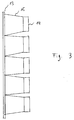
- FIG. 3 An embodiment can be seen in FIG. 3, in which five vertically aligned sensors 14 are used, to which the visible light from the X-ray converter film 13 is guided with the aid of five optical glass fiber units 15.
- the optical glass fiber units 15 on the X-ray converter film 13 are directly adjacent to one another and run toward the sensors 14 in a prism-shaped manner.
- the five small optical fiber units 15 used are generally less expensive than the larger prior art optical fiber unit and have a larger sensor capacity, thereby making it possible to use sensors that are not 100 percent work and are therefore very inexpensive as rejects. for example, when using it line sensors make it possible to use sensors in which only a fifth of the lines work.
- FIG. 4 An embodiment is shown in FIG. 4, in which only one sensor 14 is used.
- a convex lens 18 or a lens system 18 made of convex lenses is used in order to guide the visible light from the X-ray converter film 13 to the sensor 14.
- FIG. 5 corresponds to FIG. 4, with the difference that in FIG. 5 a cylindrical lens 19 or a lens system 19 with cylindrical lenses is used.
- the sensor 14 is arranged to the side of the X-ray converter film 13 and at a certain angle to it.
- the light emitted by the x-ray converter film 13 is deflected by a mirror 20, which is arranged at a certain angle to the x-ray converter film 13, and is guided to the sensor 14 by a convex lens 18.
- a prism can also be used instead of the mirror 20.
- a light amplifier can also be arranged between the X-ray converter film 13 and the sensor 14 in order to increase the sensitivity of the X-ray recording device.
Landscapes
- Health & Medical Sciences (AREA)
- Life Sciences & Earth Sciences (AREA)
- Medical Informatics (AREA)
- Engineering & Computer Science (AREA)
- Radiology & Medical Imaging (AREA)
- Biomedical Technology (AREA)
- Biophysics (AREA)
- High Energy & Nuclear Physics (AREA)
- Oral & Maxillofacial Surgery (AREA)
- Nuclear Medicine, Radiotherapy & Molecular Imaging (AREA)
- Optics & Photonics (AREA)
- Pathology (AREA)
- Dentistry (AREA)
- Physics & Mathematics (AREA)
- Heart & Thoracic Surgery (AREA)
- Molecular Biology (AREA)
- Surgery (AREA)
- Animal Behavior & Ethology (AREA)
- General Health & Medical Sciences (AREA)
- Public Health (AREA)
- Veterinary Medicine (AREA)
- Apparatus For Radiation Diagnosis (AREA)
- Radiation-Therapy Devices (AREA)
- Analysing Materials By The Use Of Radiation (AREA)
Applications Claiming Priority (6)
| Application Number | Priority Date | Filing Date | Title |
|---|---|---|---|
| DE4437077 | 1994-10-17 | ||
| DE4437077 | 1994-10-17 | ||
| DE4441974 | 1994-11-25 | ||
| DE4441974 | 1994-11-25 | ||
| DE4446960 | 1994-12-28 | ||
| DE4446960A DE4446960A1 (de) | 1994-10-17 | 1994-12-28 | Röntgenaufnahmegerät |
Publications (1)
| Publication Number | Publication Date |
|---|---|
| EP0707828A1 true EP0707828A1 (fr) | 1996-04-24 |
Family
ID=27206878
Family Applications (1)
| Application Number | Title | Priority Date | Filing Date |
|---|---|---|---|
| EP95103081A Withdrawn EP0707828A1 (fr) | 1994-10-17 | 1995-03-03 | Appareil de radiographie |
Country Status (5)
| Country | Link |
|---|---|
| US (1) | US5793838A (fr) |
| EP (1) | EP0707828A1 (fr) |
| JP (1) | JPH08206109A (fr) |
| DE (1) | DE9421296U1 (fr) |
| FI (1) | FI951872L (fr) |
Families Citing this family (9)
| Publication number | Priority date | Publication date | Assignee | Title |
|---|---|---|---|---|
| JP3807833B2 (ja) * | 1996-12-10 | 2006-08-09 | 株式会社モリタ製作所 | X線撮影装置 |
| FI120561B (fi) * | 2000-03-07 | 2009-11-30 | Planmeca Oy | Digitaalikamera, kuvantamislaite ja menetelmä digitaalisessa kuvantamisessa |
| JP3964271B2 (ja) * | 2001-06-22 | 2007-08-22 | 株式会社モリタ製作所 | 医療用走査型デジタルx線撮影装置 |
| US7086859B2 (en) * | 2003-06-10 | 2006-08-08 | Gendex Corporation | Compact digital intraoral camera system |
| US7099428B2 (en) * | 2002-06-25 | 2006-08-29 | The Regents Of The University Of Michigan | High spatial resolution X-ray computed tomography (CT) system |
| DE102005015707A1 (de) * | 2005-04-05 | 2006-10-12 | Dürr Dental GmbH & Co. KG | Panorama-Aufnahmeeinrichtung für ein Panorama-Röntgengerät |
| CN105361903B (zh) * | 2015-11-17 | 2020-10-20 | 南京大学医学院附属口腔医院 | 基于曲面体层摄影的牙齿及颌骨位置的校正方法 |
| CN106725588B (zh) * | 2017-01-18 | 2021-02-05 | 佛山市邦宁电子科技有限公司 | 一种便携式牙科x光传感器及牙科x光成像方法 |
| CN109545810A (zh) * | 2018-11-20 | 2019-03-29 | 京东方科技集团股份有限公司 | 一种平板探测器及其制备方法 |
Citations (7)
| Publication number | Priority date | Publication date | Assignee | Title |
|---|---|---|---|---|
| DE2616714A1 (de) * | 1976-04-15 | 1977-10-27 | Philips Patentverwaltung | Verfahren zur schichtweisen darstellung von objekten aus ueberlagerungsbildern unterschiedlicher bildebenen |
| US4298800A (en) * | 1978-02-27 | 1981-11-03 | Computome Corporation | Tomographic apparatus and method for obtaining three-dimensional information by radiation scanning |
| EP0046609A1 (fr) * | 1980-08-21 | 1982-03-03 | Koninklijke Philips Electronics N.V. | Appareil de radiographie à faisceau en forme d'éventail |
| US4696022A (en) * | 1984-01-27 | 1987-09-22 | University Of Pittsburgh | Stereoscopic radiography apparatus and method |
| DE8524243U1 (de) * | 1985-08-23 | 1988-06-16 | Siemens AG, 1000 Berlin und 8000 München | Zahnärztliches Röntgendiagnostikgerät |
| EP0279294A1 (fr) * | 1987-02-16 | 1988-08-24 | Siemens Aktiengesellschaft | Installation de radiodiagnostic dentaire pour réaliser une tomographie panoramique de la mâchoire d'un patient |
| EP0574183A1 (fr) * | 1992-06-04 | 1993-12-15 | Teijin Limited | Méthode et appareil de mesure du tissu osseux |
Family Cites Families (4)
| Publication number | Priority date | Publication date | Assignee | Title |
|---|---|---|---|---|
| EP0357944B1 (fr) * | 1988-08-12 | 1993-09-22 | Siemens Aktiengesellschaft | Installation de radiodiagnostic dentaire pour réaliser une tomographie panoramique de la mâchoire d'un patient |
| JP2507282Y2 (ja) * | 1990-11-26 | 1996-08-14 | 株式会社モリタ製作所 | 医療用x線画像検出装置 |
| JPH06277213A (ja) * | 1993-03-26 | 1994-10-04 | Hamamatsu Photonics Kk | 医療用x線画像検出装置及びこれを用いたx線断層撮影装置 |
| JPH07211877A (ja) * | 1994-01-21 | 1995-08-11 | Hamamatsu Photonics Kk | 放射線像検出器及び放射線像検出装置 |
-
1994
- 1994-12-28 DE DE9421296U patent/DE9421296U1/de not_active Expired - Lifetime
-
1995
- 1995-03-03 EP EP95103081A patent/EP0707828A1/fr not_active Withdrawn
- 1995-04-20 FI FI951872A patent/FI951872L/fi unknown
- 1995-10-16 US US08/543,793 patent/US5793838A/en not_active Expired - Fee Related
- 1995-10-17 JP JP7293297A patent/JPH08206109A/ja active Pending
Patent Citations (7)
| Publication number | Priority date | Publication date | Assignee | Title |
|---|---|---|---|---|
| DE2616714A1 (de) * | 1976-04-15 | 1977-10-27 | Philips Patentverwaltung | Verfahren zur schichtweisen darstellung von objekten aus ueberlagerungsbildern unterschiedlicher bildebenen |
| US4298800A (en) * | 1978-02-27 | 1981-11-03 | Computome Corporation | Tomographic apparatus and method for obtaining three-dimensional information by radiation scanning |
| EP0046609A1 (fr) * | 1980-08-21 | 1982-03-03 | Koninklijke Philips Electronics N.V. | Appareil de radiographie à faisceau en forme d'éventail |
| US4696022A (en) * | 1984-01-27 | 1987-09-22 | University Of Pittsburgh | Stereoscopic radiography apparatus and method |
| DE8524243U1 (de) * | 1985-08-23 | 1988-06-16 | Siemens AG, 1000 Berlin und 8000 München | Zahnärztliches Röntgendiagnostikgerät |
| EP0279294A1 (fr) * | 1987-02-16 | 1988-08-24 | Siemens Aktiengesellschaft | Installation de radiodiagnostic dentaire pour réaliser une tomographie panoramique de la mâchoire d'un patient |
| EP0574183A1 (fr) * | 1992-06-04 | 1993-12-15 | Teijin Limited | Méthode et appareil de mesure du tissu osseux |
Also Published As
| Publication number | Publication date |
|---|---|
| JPH08206109A (ja) | 1996-08-13 |
| DE9421296U1 (de) | 1996-02-22 |
| FI951872A7 (fi) | 1996-04-18 |
| US5793838A (en) | 1998-08-11 |
| FI951872A0 (fi) | 1995-04-20 |
| FI951872L (fi) | 1996-04-18 |
Similar Documents
| Publication | Publication Date | Title |
|---|---|---|
| DE69317570T2 (de) | Pupillometer | |
| DE68918751T2 (de) | Bildaufnahme- und Verarbeitungseinrichtung. | |
| EP1247133B1 (fr) | Dispositif optique sous forme de lunette-loupe dote d'un dispositif autofocus | |
| DE102017101188B4 (de) | Mikroskop und Verfahren zum Mikroskopieren einer Probe | |
| DE69229778T2 (de) | Objektivlinsensystem für stereo-video-endoskop | |
| EP2786696B1 (fr) | Système de caméra dentaire | |
| DE102010017543A1 (de) | Vorrichtung und Verfahren zur kombinierten optischen und nuklearen Bilderfassung | |
| EP3293558B1 (fr) | Dispositif de détection d'une image stéréo | |
| DE69614227T2 (de) | Modulares Sensorsystem für eine digitale Strahlungsbildaufnahmevorrichtung und Methode zur Konstruktion des Sensorsystems | |
| EP0362427A1 (fr) | Installation de radiodiagnostic comportant un détecteur de brillance moyenne d'image | |
| EP0707828A1 (fr) | Appareil de radiographie | |
| DE3313217A1 (de) | Einrichtung zum erzeugen vollstaendiger dreidimensionaler darstellungen eines raeumlichen objektes | |
| EP0534150A1 (fr) | Limitation de l'hyperluminosité pour un appareil de vision nocturne | |
| EP1058860B1 (fr) | Camera et notamment camera dentaire modulaire | |
| DE69618072T2 (de) | Binokulare Bildaufnahmeanordnung | |
| DE19520606B4 (de) | Vorrichtung zur optischen Untersuchung von Oberflächen | |
| DE3006749C2 (de) | Röntgenstereoeinbrichtung | |
| DE102005048232B4 (de) | Rückfahrkamerasystem und Verfahren zum Anzeigen von Informationen zu einer rückwärtigen Sicht aus einem Fahrzeug | |
| DE4446960A1 (de) | Röntgenaufnahmegerät | |
| DE3525526C2 (de) | Laufbild-Filmkamera mit Sucherlupen-Verlängerung | |
| DE3943712C2 (de) | Endoskop mit einer Videokamera | |
| EP1262750B1 (fr) | Dispositif de définition de la couleur | |
| DE3126938C3 (de) | Vorrichtung zur Bild-Auswertung | |
| DE1953352C (de) | Ziel- und Beobachtungseinrichtung mit zwei elektrooptischen Beobachtungsgeräten | |
| WO2005102169A2 (fr) | Emetteur de rayons x et procede pour generer et representer des radiographies |
Legal Events
| Date | Code | Title | Description |
|---|---|---|---|
| PUAI | Public reference made under article 153(3) epc to a published international application that has entered the european phase |
Free format text: ORIGINAL CODE: 0009012 |
|
| AK | Designated contracting states |
Kind code of ref document: A1 Designated state(s): DE FR IT SE |
|
| 17P | Request for examination filed |
Effective date: 19961022 |
|
| STAA | Information on the status of an ep patent application or granted ep patent |
Free format text: STATUS: THE APPLICATION IS DEEMED TO BE WITHDRAWN |
|
| 18D | Application deemed to be withdrawn |
Effective date: 20001003 |