EP0706830B1 - Handbetätigte Sprühvorrichtung, welche Luft als Sprühmittel verwendet - Google Patents
Handbetätigte Sprühvorrichtung, welche Luft als Sprühmittel verwendet Download PDFInfo
- Publication number
- EP0706830B1 EP0706830B1 EP94830434A EP94830434A EP0706830B1 EP 0706830 B1 EP0706830 B1 EP 0706830B1 EP 94830434 A EP94830434 A EP 94830434A EP 94830434 A EP94830434 A EP 94830434A EP 0706830 B1 EP0706830 B1 EP 0706830B1
- Authority
- EP
- European Patent Office
- Prior art keywords
- liquid
- duct
- air
- spray device
- tubular body
- Prior art date
- Legal status (The legal status is an assumption and is not a legal conclusion. Google has not performed a legal analysis and makes no representation as to the accuracy of the status listed.)
- Expired - Lifetime
Links
Images

Classifications
-
- B—PERFORMING OPERATIONS; TRANSPORTING
- B05—SPRAYING OR ATOMISING IN GENERAL; APPLYING FLUENT MATERIALS TO SURFACES, IN GENERAL
- B05B—SPRAYING APPARATUS; ATOMISING APPARATUS; NOZZLES
- B05B7/00—Spraying apparatus for discharge of liquids or other fluent materials from two or more sources, e.g. of liquid and air, of powder and gas
- B05B7/02—Spray pistols; Apparatus for discharge
- B05B7/04—Spray pistols; Apparatus for discharge with arrangements for mixing liquids or other fluent materials before discharge
- B05B7/0416—Spray pistols; Apparatus for discharge with arrangements for mixing liquids or other fluent materials before discharge with arrangements for mixing one gas and one liquid
-
- B—PERFORMING OPERATIONS; TRANSPORTING
- B05—SPRAYING OR ATOMISING IN GENERAL; APPLYING FLUENT MATERIALS TO SURFACES, IN GENERAL
- B05B—SPRAYING APPARATUS; ATOMISING APPARATUS; NOZZLES
- B05B11/00—Single-unit hand-held apparatus in which flow of contents is produced by the muscular force of the operator at the moment of use
- B05B11/01—Single-unit hand-held apparatus in which flow of contents is produced by the muscular force of the operator at the moment of use characterised by the means producing the flow
- B05B11/10—Pump arrangements for transferring the contents from the container to a pump chamber by a sucking effect and forcing the contents out through the dispensing nozzle
- B05B11/1042—Components or details
- B05B11/1073—Springs
- B05B11/1074—Springs located outside pump chambers
-
- B—PERFORMING OPERATIONS; TRANSPORTING
- B05—SPRAYING OR ATOMISING IN GENERAL; APPLYING FLUENT MATERIALS TO SURFACES, IN GENERAL
- B05B—SPRAYING APPARATUS; ATOMISING APPARATUS; NOZZLES
- B05B11/00—Single-unit hand-held apparatus in which flow of contents is produced by the muscular force of the operator at the moment of use
- B05B11/01—Single-unit hand-held apparatus in which flow of contents is produced by the muscular force of the operator at the moment of use characterised by the means producing the flow
- B05B11/10—Pump arrangements for transferring the contents from the container to a pump chamber by a sucking effect and forcing the contents out through the dispensing nozzle
- B05B11/1042—Components or details
- B05B11/1073—Springs
- B05B11/1077—Springs characterised by a particular shape or material
-
- B—PERFORMING OPERATIONS; TRANSPORTING
- B05—SPRAYING OR ATOMISING IN GENERAL; APPLYING FLUENT MATERIALS TO SURFACES, IN GENERAL
- B05B—SPRAYING APPARATUS; ATOMISING APPARATUS; NOZZLES
- B05B11/00—Single-unit hand-held apparatus in which flow of contents is produced by the muscular force of the operator at the moment of use
- B05B11/01—Single-unit hand-held apparatus in which flow of contents is produced by the muscular force of the operator at the moment of use characterised by the means producing the flow
- B05B11/10—Pump arrangements for transferring the contents from the container to a pump chamber by a sucking effect and forcing the contents out through the dispensing nozzle
- B05B11/1087—Combination of liquid and air pumps
-
- B—PERFORMING OPERATIONS; TRANSPORTING
- B05—SPRAYING OR ATOMISING IN GENERAL; APPLYING FLUENT MATERIALS TO SURFACES, IN GENERAL
- B05B—SPRAYING APPARATUS; ATOMISING APPARATUS; NOZZLES
- B05B7/00—Spraying apparatus for discharge of liquids or other fluent materials from two or more sources, e.g. of liquid and air, of powder and gas
- B05B7/02—Spray pistols; Apparatus for discharge
- B05B7/10—Spray pistols; Apparatus for discharge producing a swirling discharge
Definitions
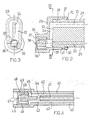
- the present invention relates to an atomising spray device for liquids which is manually operable and uses air as the atomising fluid, comprising a container for the liquid to be sprayed, a tubular body associated with the liquid container and having a free end, a swirl chamber member with a delivery nozzle and vortex-forming means for causing fluid to swirl mounted in correspondence with the free end of the tubular body, a first duct for carrying liquid from the container, a second duct for conveying air from the outside, both of these ducts being housed, at least along part of their lengths, within the tubular body, as well as respective pump members arranged in the liquid duct and in the air duct, these pump members being manually operable at the same time.
- a second swirl chamber is arranged around the outwardly-facing end of the delivery nozzle and, being supplied with air through a second duct, forms a swirling jet which collides with that of the liquid thereby greatly diminishing the size of the liquid droplets.
- the air jet pressurised by a manually-operated pump, is conveyed into the vicinity of the nozzle and impinges on the jet of liquid which is coming out of this nozzle already partially atomised by the vortex-forming members. In this way the droplets of liquid are further broken down, thereby obtaining very fine atomisation.
- the liquid and the air are pumped by respective pumps which can be operated simultaneously by means of a single control.
- the object of the present invention is therefore to overcome problems encountered in prior art atomiser spray devices.
- reference 1 indicates a container for liquid to be delivered which may be of various types such as, insecticide, air freshener or hair spray.
- the container 1 is connected by means of a coupling 2 to a column 3 which is an integral part of a pumping assembly with two pump members, one for the liquid in the container 1 and one for air.
- the column 3 is traversed longitudinally by a duct 4 which is connected by a connector 5 to a tube 6 which dips into the liquid in the container 1.
- a cylindrical body 8 defines a transverse duct 7 which communicates with the duct 4 and which houses a movable piston 9, fitted with seal rings 10, which is securely fixed to a control grip 11 by means of a pin 12 so as to form a first pump member.
- the grip 11 is movable relative to the column 3, to which it is parallel, and is guided between a face 13 of the container 1 and a face 14 of a shell cover 15 fixed to the column 3 by snap means such as those indicated 16 and 17.
- a bellows member 18 is also fixed to the grip 11 and is connected to the column 3 by an annular stem 19.
- the bellows member 18 constitutes the pump member for the air which is pressurised at each movement of the grip 11 and forced into a duct 20 formed in the body of the column 3.
- the ducts 4 and 20 communicate through respective connectors 21 and 22 with respective further ducts 23 and 24 formed in a tubular body 25 connected to the column 3 by means of a hook 26 and to the shell 15 by means of projections 27.
- the connectors 5, 21 and 22 have one-way valves, not shown in detail as they are entirely conventional, which are required for the pump members to operate and for the fluids to be conveyed correctly.
- a cap 29 is fitted to the free end portion 28 of the tubular body 25 by snap engagement means 30, 31.
- a channel 34 is formed which puts the outlet of the air duct 24 into communication with a mixing chamber 35 where the air flow is mixed with a flow of liquid arriving from the duct 23.
- the transverse dimensions of the chamber 35 are greater than the diameter of the liquid duct 23.
- the cap 29 has a tubular seat 36 housing a swirl-chamber insert 37 having a nozzle 38 and vortex-forming means, in themselves known, indicated 39.
- the insert 37 is arranged adjacent the mixing chamber 35 so that this chamber is upstream of the delivery nozzle 38.
- the tubular body is indicated 40, the liquid duct 41 and the air duct 42. It can be seen that the air duct 42 is coaxial with the liquid duct 41 which opens into a chamber 43 which communicates around its circumference directly with the outlet of the air duct 42.
- the chamber 43 is defined at its opposite end from the outlet of the duct 41, by an end face 44 of a cylindrical appendage 45 projecting from a swirl-chamber insert 46.
- the latter is provided, in conventional manner, with a delivery nozzle 47 and vortex-forming elements 48 and is housed directly inside the free end portion 49 of the tubular body 40.
- the spray device is operated by repeated pressure on and release of the grip which causes the simultaneous operation of the liquid pump members, that is the piston 9 in the duct 7, and of the air pump members, that is the bellows 18.
- the liquid thus drawn from the container 1 enters the duct 23, or the duct 41, in the quantity determined by the structure and dimensions of the members 7 and 9 which form the pump.
Landscapes
- Nozzles (AREA)
- Containers And Packaging Bodies Having A Special Means To Remove Contents (AREA)
Claims (6)
- Handbetätigte Sprühvorrichtung, welche Luft als Sprühmittel verwendet, bestehend aus einem Behälter (1) für die zu sprühende Flüssigkeit, einem rohrförmigen Körper (25, 40), der mit dem Flüssigkeitsbehälter verbunden ist und ein freies Ende (28, 49) aufweist, einer Wirbelkammer (37, 46) mit einer Spenderdüse (38, 47) und einem wirbelbildenden Mittel (39, 48), das bewirkt, daß das Sprühmittel bis in den Bereich des freien Endes des rohrförmigen Körpers hinaufwirbelt, einer ersten Röhrenleitung (23, 41) zur Beförderung von Flüssigkeit aus dem Behälter, einer zweiten Röhrenleitung (24, 42) zur Beförderung von Luft von außerhalb, wobei diese beiden Röhrenleitungen zumindest über Teile ihrer Länge innerhalb des rohrförmigen Körpers (25, 40) gelagert sind und jeweilige Pumpelemente (7, 9 - 18) in der Röhrenleitung für die Flüssigkeit bzw. in der Röhrenleitung für die Luft angeordnet sind, wobei die Pumpelemente gleichzeitig von Hand betätigt werden können,
dadurch gekennzeichnet, daß der rohrförmige Körper (25, 40) eine Luft-Flüssigkeits-Mischkammer (35, 43) umfaßt, die sich stromaufwärts von der Wirbelkammer (37, 46) befindet, und daß die Röhrenleitungen für Flüssigkeit und Luft frei in die Mischkammer münden, wobei die Durchmesser der Röhrenleitungen in einem vorbestimmten Verhältnis zueinander stehen, das mit dem Luft-Flüssigkeits-Mischverhältnis korreliert, das in der Mischkammer (35, 43) erzielt werden soll. - Sprühvorrichtung nach Anspruch 1,
dadurch gekennzeichnet, daß das Verhältnis des Durchmessers der Flüssigkeitsröhrenleitung (23, 41) zu dem Durchmesser der Luftröhrenleitung (24, 42) zwischen ½ und 1/3 liegt. - Sprühvorrichtung nach Anspruch 1 und 2,
dadurch gekennzeichnet, daß die Flüssigkeits- und Luftröhrenleitungen parallel zueinander verlaufen und innerhalb des rohrförmiges Körpers in Querrichtung voneinander beabstandet sind. - Sprühvorrichtung nach Anspruch 3,
dadurch gekennzeichnet, daß die Flüssigkeitsröhrenleitung (23) sich unterhalb der Luftröhrenleitung in Richtung der natürlichen Schwerkraft befindet. - Sprühvorrichtung nach Anspruch 1 und 2,
dadurch gekennzeichnet, daß die Röhrenleitungen für Flüssigkeit (41) und Luft (42) koaxial angeordnet sind, wobei die Luftröhrenleitung die Flüssigkeitsröhrenleitung ringförmig umgibt. - Sprühvorrichtung nach den Ansprüchen 1 bis 5,
dadurch gekennzeichnet, daß die Mischkammer (35, 43) so angeordnet ist, daß sie dem in sie mündenden Ausgang der Flüssigkeitsröhrenleitung (23, 41) zugewandt ist, wobei die Abmessungen dieser Kammer in Querrichtung größer sind als der Durchmesser der Flüssigkeitsröhrenleitung, wobei zwischen der Mischkammer selbst und der Luftröhrenleitung ein Verbindungsdurchgang (34) vorgesehen ist.
Priority Applications (3)
| Application Number | Priority Date | Filing Date | Title |
|---|---|---|---|
| DE69405106T DE69405106T2 (de) | 1994-09-16 | 1994-09-16 | Handbetätigte Sprühvorrichtung, welche Luft als Sprühmittel verwendet |
| ES94830434T ES2108410T3 (es) | 1994-09-16 | 1994-09-16 | Dispositivo pulverizador de atomizacion para liquidos, accionable manualmente y que usa aire como fluido de atomizacion. |
| EP94830434A EP0706830B1 (de) | 1994-09-16 | 1994-09-16 | Handbetätigte Sprühvorrichtung, welche Luft als Sprühmittel verwendet |
Applications Claiming Priority (1)
| Application Number | Priority Date | Filing Date | Title |
|---|---|---|---|
| EP94830434A EP0706830B1 (de) | 1994-09-16 | 1994-09-16 | Handbetätigte Sprühvorrichtung, welche Luft als Sprühmittel verwendet |
Publications (2)
| Publication Number | Publication Date |
|---|---|
| EP0706830A1 EP0706830A1 (de) | 1996-04-17 |
| EP0706830B1 true EP0706830B1 (de) | 1997-08-20 |
Family
ID=8218522
Family Applications (1)
| Application Number | Title | Priority Date | Filing Date |
|---|---|---|---|
| EP94830434A Expired - Lifetime EP0706830B1 (de) | 1994-09-16 | 1994-09-16 | Handbetätigte Sprühvorrichtung, welche Luft als Sprühmittel verwendet |
Country Status (3)
| Country | Link |
|---|---|
| EP (1) | EP0706830B1 (de) |
| DE (1) | DE69405106T2 (de) |
| ES (1) | ES2108410T3 (de) |
Families Citing this family (4)
| Publication number | Priority date | Publication date | Assignee | Title |
|---|---|---|---|---|
| DE10047668A1 (de) * | 2000-09-26 | 2002-04-11 | Aromata Internat Duftleuchten | Beduftungsgerät |
| US7967171B2 (en) | 2004-10-11 | 2011-06-28 | Meadwestvaco Calmar, Inc. | Air foaming pump trigger sprayer |
| GB0515592D0 (en) | 2005-07-28 | 2005-09-07 | Glaxo Group Ltd | Nozzle for a nasal inhaler |
| US9327253B2 (en) | 2010-06-15 | 2016-05-03 | Brightwell Dispensers Limited | Foam pump |
Family Cites Families (4)
| Publication number | Priority date | Publication date | Assignee | Title |
|---|---|---|---|---|
| NL132938C (de) * | 1963-05-03 | |||
| US4122979A (en) * | 1976-06-01 | 1978-10-31 | Laauwe Robert H | Squeeze bottle containing a liquid product and operative whether upright or inverted |
| DE4102632A1 (de) * | 1991-01-30 | 1992-08-06 | Pfeiffer Erich Gmbh & Co Kg | Austragduese fuer medien |
| CH680582A5 (de) * | 1991-04-23 | 1992-09-30 | Supermatic Kunststoff Ag |
-
1994
- 1994-09-16 EP EP94830434A patent/EP0706830B1/de not_active Expired - Lifetime
- 1994-09-16 ES ES94830434T patent/ES2108410T3/es not_active Expired - Lifetime
- 1994-09-16 DE DE69405106T patent/DE69405106T2/de not_active Expired - Lifetime
Also Published As
| Publication number | Publication date |
|---|---|
| DE69405106D1 (de) | 1997-09-25 |
| EP0706830A1 (de) | 1996-04-17 |
| DE69405106T2 (de) | 1998-01-29 |
| ES2108410T3 (es) | 1997-12-16 |
Similar Documents
| Publication | Publication Date | Title |
|---|---|---|
| US4989787A (en) | Liquid spray gun accessories | |
| US5088649A (en) | Pump sprayable dispensing system for vegetable oil based pan coatings | |
| EP1056547B1 (de) | Flüssigkeitszerstäuber und düseneinsatz | |
| US5722598A (en) | Spraying nozzle for regulating the rate of flow per unit of time | |
| US5249747A (en) | Sprayable dispensing system for viscous vegetable oils and apparatus therefor | |
| US5221026A (en) | Apparatus for dispensing mixtures of liquids and pressurized gas | |
| EP1184084B1 (de) | Schlauchendsprühgerät vom Ansaugtyp | |
| US6561438B1 (en) | Foam generating nozzle assembly | |
| US6189625B1 (en) | Liquid mist fire extinguisher | |
| US8955769B2 (en) | Vortex atomizing foam pump and refill unit utilizing same | |
| KR950700127A (ko) | 큰 직경 거품을 이용하는 스프레이 장치를 포함하는 소비제품 패키지(consumer product package incorporatimg a spray device utilizing large diameter bubbles) | |
| US6015100A (en) | Foam generating nozzle assembly with interchangeable nozzle tip | |
| CN102781791A (zh) | 喷雾排放组件 | |
| US6896203B1 (en) | Aspiration sprayer | |
| US5447273A (en) | Pneumatic timed spray dispenser | |
| EP0706830B1 (de) | Handbetätigte Sprühvorrichtung, welche Luft als Sprühmittel verwendet | |
| US5082185A (en) | Spray wand without liquid leakage | |
| US4813609A (en) | Spray nozzle | |
| US3658254A (en) | Liquid atomizing apparatus | |
| GB1577428A (en) | Fluid mixing device | |
| US5397058A (en) | Low pressure fumeless spray gun | |
| US6102255A (en) | Invertible dispensing means for spray containers | |
| EP1603681B1 (de) | Fluidabgabevorrichtung | |
| JPH0586266B2 (de) | ||
| US20130140331A1 (en) | Liquid dispenser |
Legal Events
| Date | Code | Title | Description |
|---|---|---|---|
| PUAI | Public reference made under article 153(3) epc to a published international application that has entered the european phase |
Free format text: ORIGINAL CODE: 0009012 |
|
| 17P | Request for examination filed |
Effective date: 19950626 |
|
| AK | Designated contracting states |
Kind code of ref document: A1 Designated state(s): DE ES FR GB IT NL |
|
| AX | Request for extension of the european patent |
Free format text: LT;SI |
|
| RAX | Requested extension states of the european patent have changed |
Free format text: LT;SI |
|
| GRAG | Despatch of communication of intention to grant |
Free format text: ORIGINAL CODE: EPIDOS AGRA |
|
| GRAH | Despatch of communication of intention to grant a patent |
Free format text: ORIGINAL CODE: EPIDOS IGRA |
|
| 17Q | First examination report despatched |
Effective date: 19970114 |
|
| GRAH | Despatch of communication of intention to grant a patent |
Free format text: ORIGINAL CODE: EPIDOS IGRA |
|
| RBV | Designated contracting states (corrected) |
Designated state(s): DE ES FR GB IT NL |
|
| GRAA | (expected) grant |
Free format text: ORIGINAL CODE: 0009210 |
|
| RAP1 | Party data changed (applicant data changed or rights of an application transferred) |
Owner name: GUALA DISPENSING S.R.L. |
|
| AK | Designated contracting states |
Kind code of ref document: B1 Designated state(s): DE ES FR GB IT NL |
|
| AX | Request for extension of the european patent |
Free format text: LT;SI |
|
| REF | Corresponds to: |
Ref document number: 69405106 Country of ref document: DE Date of ref document: 19970925 |
|
| ITF | It: translation for a ep patent filed | ||
| ET | Fr: translation filed | ||
| REG | Reference to a national code |
Ref country code: ES Ref legal event code: FG2A Ref document number: 2108410 Country of ref document: ES Kind code of ref document: T3 |
|
| PLBE | No opposition filed within time limit |
Free format text: ORIGINAL CODE: 0009261 |
|
| STAA | Information on the status of an ep patent application or granted ep patent |
Free format text: STATUS: NO OPPOSITION FILED WITHIN TIME LIMIT |
|
| 26N | No opposition filed | ||
| PGFP | Annual fee paid to national office [announced via postgrant information from national office to epo] |
Ref country code: NL Payment date: 19980819 Year of fee payment: 5 |
|
| PG25 | Lapsed in a contracting state [announced via postgrant information from national office to epo] |
Ref country code: NL Free format text: LAPSE BECAUSE OF NON-PAYMENT OF DUE FEES Effective date: 20000401 |
|
| NLV4 | Nl: lapsed or anulled due to non-payment of the annual fee |
Effective date: 20000401 |
|
| REG | Reference to a national code |
Ref country code: GB Ref legal event code: IF02 |
|
| PGFP | Annual fee paid to national office [announced via postgrant information from national office to epo] |
Ref country code: ES Payment date: 20090728 Year of fee payment: 16 |
|
| PGFP | Annual fee paid to national office [announced via postgrant information from national office to epo] |
Ref country code: GB Payment date: 20090922 Year of fee payment: 16 |
|
| PGFP | Annual fee paid to national office [announced via postgrant information from national office to epo] |
Ref country code: DE Payment date: 20090922 Year of fee payment: 16 |
|
| PGFP | Annual fee paid to national office [announced via postgrant information from national office to epo] |
Ref country code: IT Payment date: 20090912 Year of fee payment: 16 Ref country code: FR Payment date: 20091016 Year of fee payment: 16 |
|
| GBPC | Gb: european patent ceased through non-payment of renewal fee |
Effective date: 20100916 |
|
| PG25 | Lapsed in a contracting state [announced via postgrant information from national office to epo] |
Ref country code: IT Free format text: LAPSE BECAUSE OF NON-PAYMENT OF DUE FEES Effective date: 20100916 |
|
| REG | Reference to a national code |
Ref country code: FR Ref legal event code: ST Effective date: 20110531 |
|
| REG | Reference to a national code |
Ref country code: DE Ref legal event code: R119 Ref document number: 69405106 Country of ref document: DE Effective date: 20110401 |
|
| PG25 | Lapsed in a contracting state [announced via postgrant information from national office to epo] |
Ref country code: DE Free format text: LAPSE BECAUSE OF NON-PAYMENT OF DUE FEES Effective date: 20110401 Ref country code: FR Free format text: LAPSE BECAUSE OF NON-PAYMENT OF DUE FEES Effective date: 20100930 |
|
| PG25 | Lapsed in a contracting state [announced via postgrant information from national office to epo] |
Ref country code: GB Free format text: LAPSE BECAUSE OF NON-PAYMENT OF DUE FEES Effective date: 20100916 |
|
| REG | Reference to a national code |
Ref country code: ES Ref legal event code: FD2A Effective date: 20111019 |
|
| PG25 | Lapsed in a contracting state [announced via postgrant information from national office to epo] |
Ref country code: ES Free format text: LAPSE BECAUSE OF NON-PAYMENT OF DUE FEES Effective date: 20100917 |