EP0706830B1 - A manually operable atomising spray device for liquids which uses air as the atomiser fluid - Google Patents
A manually operable atomising spray device for liquids which uses air as the atomiser fluid Download PDFInfo
- Publication number
- EP0706830B1 EP0706830B1 EP94830434A EP94830434A EP0706830B1 EP 0706830 B1 EP0706830 B1 EP 0706830B1 EP 94830434 A EP94830434 A EP 94830434A EP 94830434 A EP94830434 A EP 94830434A EP 0706830 B1 EP0706830 B1 EP 0706830B1
- Authority
- EP
- European Patent Office
- Prior art keywords
- liquid
- duct
- air
- spray device
- tubular body
- Prior art date
- Legal status (The legal status is an assumption and is not a legal conclusion. Google has not performed a legal analysis and makes no representation as to the accuracy of the status listed.)
- Expired - Lifetime
Links
Images

Classifications
-
- B—PERFORMING OPERATIONS; TRANSPORTING
- B05—SPRAYING OR ATOMISING IN GENERAL; APPLYING FLUENT MATERIALS TO SURFACES, IN GENERAL
- B05B—SPRAYING APPARATUS; ATOMISING APPARATUS; NOZZLES
- B05B7/00—Spraying apparatus for discharge of liquids or other fluent materials from two or more sources, e.g. of liquid and air, of powder and gas
- B05B7/02—Spray pistols; Apparatus for discharge
- B05B7/04—Spray pistols; Apparatus for discharge with arrangements for mixing liquids or other fluent materials before discharge
- B05B7/0416—Spray pistols; Apparatus for discharge with arrangements for mixing liquids or other fluent materials before discharge with arrangements for mixing one gas and one liquid
-
- B—PERFORMING OPERATIONS; TRANSPORTING
- B05—SPRAYING OR ATOMISING IN GENERAL; APPLYING FLUENT MATERIALS TO SURFACES, IN GENERAL
- B05B—SPRAYING APPARATUS; ATOMISING APPARATUS; NOZZLES
- B05B11/00—Single-unit hand-held apparatus in which flow of contents is produced by the muscular force of the operator at the moment of use
- B05B11/01—Single-unit hand-held apparatus in which flow of contents is produced by the muscular force of the operator at the moment of use characterised by the means producing the flow
- B05B11/10—Pump arrangements for transferring the contents from the container to a pump chamber by a sucking effect and forcing the contents out through the dispensing nozzle
- B05B11/1042—Components or details
- B05B11/1073—Springs
- B05B11/1074—Springs located outside pump chambers
-
- B—PERFORMING OPERATIONS; TRANSPORTING
- B05—SPRAYING OR ATOMISING IN GENERAL; APPLYING FLUENT MATERIALS TO SURFACES, IN GENERAL
- B05B—SPRAYING APPARATUS; ATOMISING APPARATUS; NOZZLES
- B05B11/00—Single-unit hand-held apparatus in which flow of contents is produced by the muscular force of the operator at the moment of use
- B05B11/01—Single-unit hand-held apparatus in which flow of contents is produced by the muscular force of the operator at the moment of use characterised by the means producing the flow
- B05B11/10—Pump arrangements for transferring the contents from the container to a pump chamber by a sucking effect and forcing the contents out through the dispensing nozzle
- B05B11/1042—Components or details
- B05B11/1073—Springs
- B05B11/1077—Springs characterised by a particular shape or material
-
- B—PERFORMING OPERATIONS; TRANSPORTING
- B05—SPRAYING OR ATOMISING IN GENERAL; APPLYING FLUENT MATERIALS TO SURFACES, IN GENERAL
- B05B—SPRAYING APPARATUS; ATOMISING APPARATUS; NOZZLES
- B05B11/00—Single-unit hand-held apparatus in which flow of contents is produced by the muscular force of the operator at the moment of use
- B05B11/01—Single-unit hand-held apparatus in which flow of contents is produced by the muscular force of the operator at the moment of use characterised by the means producing the flow
- B05B11/10—Pump arrangements for transferring the contents from the container to a pump chamber by a sucking effect and forcing the contents out through the dispensing nozzle
- B05B11/1087—Combination of liquid and air pumps
-
- B—PERFORMING OPERATIONS; TRANSPORTING
- B05—SPRAYING OR ATOMISING IN GENERAL; APPLYING FLUENT MATERIALS TO SURFACES, IN GENERAL
- B05B—SPRAYING APPARATUS; ATOMISING APPARATUS; NOZZLES
- B05B7/00—Spraying apparatus for discharge of liquids or other fluent materials from two or more sources, e.g. of liquid and air, of powder and gas
- B05B7/02—Spray pistols; Apparatus for discharge
- B05B7/10—Spray pistols; Apparatus for discharge producing a swirling discharge
Definitions
- the present invention relates to an atomising spray device for liquids which is manually operable and uses air as the atomising fluid, comprising a container for the liquid to be sprayed, a tubular body associated with the liquid container and having a free end, a swirl chamber member with a delivery nozzle and vortex-forming means for causing fluid to swirl mounted in correspondence with the free end of the tubular body, a first duct for carrying liquid from the container, a second duct for conveying air from the outside, both of these ducts being housed, at least along part of their lengths, within the tubular body, as well as respective pump members arranged in the liquid duct and in the air duct, these pump members being manually operable at the same time.
- a second swirl chamber is arranged around the outwardly-facing end of the delivery nozzle and, being supplied with air through a second duct, forms a swirling jet which collides with that of the liquid thereby greatly diminishing the size of the liquid droplets.
- the air jet pressurised by a manually-operated pump, is conveyed into the vicinity of the nozzle and impinges on the jet of liquid which is coming out of this nozzle already partially atomised by the vortex-forming members. In this way the droplets of liquid are further broken down, thereby obtaining very fine atomisation.
- the liquid and the air are pumped by respective pumps which can be operated simultaneously by means of a single control.
- the object of the present invention is therefore to overcome problems encountered in prior art atomiser spray devices.
- reference 1 indicates a container for liquid to be delivered which may be of various types such as, insecticide, air freshener or hair spray.
- the container 1 is connected by means of a coupling 2 to a column 3 which is an integral part of a pumping assembly with two pump members, one for the liquid in the container 1 and one for air.
- the column 3 is traversed longitudinally by a duct 4 which is connected by a connector 5 to a tube 6 which dips into the liquid in the container 1.
- a cylindrical body 8 defines a transverse duct 7 which communicates with the duct 4 and which houses a movable piston 9, fitted with seal rings 10, which is securely fixed to a control grip 11 by means of a pin 12 so as to form a first pump member.
- the grip 11 is movable relative to the column 3, to which it is parallel, and is guided between a face 13 of the container 1 and a face 14 of a shell cover 15 fixed to the column 3 by snap means such as those indicated 16 and 17.
- a bellows member 18 is also fixed to the grip 11 and is connected to the column 3 by an annular stem 19.
- the bellows member 18 constitutes the pump member for the air which is pressurised at each movement of the grip 11 and forced into a duct 20 formed in the body of the column 3.
- the ducts 4 and 20 communicate through respective connectors 21 and 22 with respective further ducts 23 and 24 formed in a tubular body 25 connected to the column 3 by means of a hook 26 and to the shell 15 by means of projections 27.
- the connectors 5, 21 and 22 have one-way valves, not shown in detail as they are entirely conventional, which are required for the pump members to operate and for the fluids to be conveyed correctly.
- a cap 29 is fitted to the free end portion 28 of the tubular body 25 by snap engagement means 30, 31.
- a channel 34 is formed which puts the outlet of the air duct 24 into communication with a mixing chamber 35 where the air flow is mixed with a flow of liquid arriving from the duct 23.
- the transverse dimensions of the chamber 35 are greater than the diameter of the liquid duct 23.
- the cap 29 has a tubular seat 36 housing a swirl-chamber insert 37 having a nozzle 38 and vortex-forming means, in themselves known, indicated 39.
- the insert 37 is arranged adjacent the mixing chamber 35 so that this chamber is upstream of the delivery nozzle 38.
- the tubular body is indicated 40, the liquid duct 41 and the air duct 42. It can be seen that the air duct 42 is coaxial with the liquid duct 41 which opens into a chamber 43 which communicates around its circumference directly with the outlet of the air duct 42.
- the chamber 43 is defined at its opposite end from the outlet of the duct 41, by an end face 44 of a cylindrical appendage 45 projecting from a swirl-chamber insert 46.
- the latter is provided, in conventional manner, with a delivery nozzle 47 and vortex-forming elements 48 and is housed directly inside the free end portion 49 of the tubular body 40.
- the spray device is operated by repeated pressure on and release of the grip which causes the simultaneous operation of the liquid pump members, that is the piston 9 in the duct 7, and of the air pump members, that is the bellows 18.
- the liquid thus drawn from the container 1 enters the duct 23, or the duct 41, in the quantity determined by the structure and dimensions of the members 7 and 9 which form the pump.
Landscapes
- Nozzles (AREA)
- Containers And Packaging Bodies Having A Special Means To Remove Contents (AREA)
Description
- The present invention relates to an atomising spray device for liquids which is manually operable and uses air as the atomising fluid, comprising a container for the liquid to be sprayed, a tubular body associated with the liquid container and having a free end, a swirl chamber member with a delivery nozzle and vortex-forming means for causing fluid to swirl mounted in correspondence with the free end of the tubular body, a first duct for carrying liquid from the container, a second duct for conveying air from the outside, both of these ducts being housed, at least along part of their lengths, within the tubular body, as well as respective pump members arranged in the liquid duct and in the air duct, these pump members being manually operable at the same time.
- Devices of the aforesaid type are already known in the art and their use is increasingly widespread, above all for ecological reasons as they do not use toxic gases as propellants.
- An example of such prior art is described in United States Patent 3 945 574 in which the liquid to be sprayed and atomised into microscopic particles is pumped through a first duct to a delivery nozzle from which it exits in a vortex.
- In the device described in the aforesaid document, a second swirl chamber is arranged around the outwardly-facing end of the delivery nozzle and, being supplied with air through a second duct, forms a swirling jet which collides with that of the liquid thereby greatly diminishing the size of the liquid droplets.
- A further example of an atomiser of the type mentioned in the introduction is described in United States
Patent 5 147 087. - In this device also, the air jet, pressurised by a manually-operated pump, is conveyed into the vicinity of the nozzle and impinges on the jet of liquid which is coming out of this nozzle already partially atomised by the vortex-forming members. In this way the droplets of liquid are further broken down, thereby obtaining very fine atomisation.
- According to the aforementioned examples of the prior art, the liquid and the air are pumped by respective pumps which can be operated simultaneously by means of a single control.
- Although prior art atomiser spray devices are theoretically able to produce flows of highly broken down, and therefore atomised, droplets, in practice they demonstrate serious operating problems.
- With the use of simultaneously operable, manual pumps it is difficult to form both an air flow having sufficient pressure to act on the liquid jet with sufficient force to break up the droplets and a liquid flow having a flow rate which is tailored to the flow rate and the pressure of the air flow so as to enable the liquid flow to be fully atomised.
- In addition, the atomising effect of prior art devices is heavily compromised by the fact that the air and the liquid are mixed only after each has been given its swirling movement separately.
- The object of the present invention is therefore to overcome problems encountered in prior art atomiser spray devices.
- This object is achieved by a device characterised by the claims which follow.
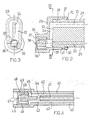
- The invention will now be described in greater detail with reference to embodiments thereof provided purely by way of non-limitative example with reference to the appended drawings, in which:
- Figure 1 is a schematic longitudinal section of a spray device according to the invention complete with pump and container for the liquid to be sprayed;
- Figure 2 shows, on an enlarged scale, the portion adjacent the nozzle of the spray device of Figure 1;
- Figure 3 is a cross-section taken on the line III-III of Figure 2; and
- Figure 4 is a longitudinal section of an alternative embodiment of the tubular body of the spray device with the air and liquid ducts arranged coaxially.
- With reference to the drawings, reference 1 indicates a container for liquid to be delivered which may be of various types such as, insecticide, air freshener or hair spray.
- The container 1 is connected by means of a
coupling 2 to a column 3 which is an integral part of a pumping assembly with two pump members, one for the liquid in the container 1 and one for air. - With reference to Figure 1, it can be seen that the column 3 is traversed longitudinally by a duct 4 which is connected by a
connector 5 to atube 6 which dips into the liquid in the container 1. - A cylindrical body 8 defines a
transverse duct 7 which communicates with the duct 4 and which houses amovable piston 9, fitted withseal rings 10, which is securely fixed to acontrol grip 11 by means of apin 12 so as to form a first pump member. - The
grip 11 is movable relative to the column 3, to which it is parallel, and is guided between aface 13 of the container 1 and aface 14 of ashell cover 15 fixed to the column 3 by snap means such as those indicated 16 and 17. - A
bellows member 18 is also fixed to thegrip 11 and is connected to the column 3 by anannular stem 19. - The
bellows member 18 constitutes the pump member for the air which is pressurised at each movement of thegrip 11 and forced into aduct 20 formed in the body of the column 3. - The
ducts 4 and 20 communicate throughrespective connectors further ducts tubular body 25 connected to the column 3 by means of ahook 26 and to theshell 15 by means ofprojections 27. - The
connectors - With reference to Figures 2 and 3, it can be seen that a
cap 29 is fitted to thefree end portion 28 of thetubular body 25 by snap engagement means 30, 31. - Inside the
cap 29, a flatinner face 32 of which bears against theend face 33 of theend portion 28 of thetubular body 25, achannel 34 is formed which puts the outlet of theair duct 24 into communication with amixing chamber 35 where the air flow is mixed with a flow of liquid arriving from theduct 23. - The transverse dimensions of the
chamber 35 are greater than the diameter of theliquid duct 23. - The
cap 29 has atubular seat 36 housing a swirl-chamber insert 37 having anozzle 38 and vortex-forming means, in themselves known, indicated 39. - The
insert 37 is arranged adjacent themixing chamber 35 so that this chamber is upstream of thedelivery nozzle 38. - With reference to Figure 4, which shows an alternative embodiment of the invention, the tubular body is indicated 40, the
liquid duct 41 and theair duct 42. It can be seen that theair duct 42 is coaxial with theliquid duct 41 which opens into achamber 43 which communicates around its circumference directly with the outlet of theair duct 42. - The air and the liquid are mixed in this
chamber 43. - The
chamber 43 is defined at its opposite end from the outlet of theduct 41, by anend face 44 of acylindrical appendage 45 projecting from a swirl-chamber insert 46. - The latter is provided, in conventional manner, with a
delivery nozzle 47 and vortex-formingelements 48 and is housed directly inside thefree end portion 49 of thetubular body 40. - It will be appreciated from the above that the spray device is operated by repeated pressure on and release of the grip which causes the simultaneous operation of the liquid pump members, that is the
piston 9 in theduct 7, and of the air pump members, that is thebellows 18. - The liquid thus drawn from the container 1 enters the
duct 23, or theduct 41, in the quantity determined by the structure and dimensions of themembers - At the same time, a predetermined quantity of air, dependent on the capacity of the
bellows 18, is forced under pressure into theair duct - If the ratio of the diameter of the liquid duct, 23 or 41, to that of the air duct, 24 or 42, is maintained preferably between 1/2 and 1/3, a correctly proportioned liquid-air mix is achieved in the
chamber - When this liquid-air mix passes through the vortex-forming members of the
insert nozzle - The embodiment illustrated in Figures 2 and 3 is particularly suited to this final purpose since, as the
liquid duct 23 is beneath theair duct 24, the natural direction of gravity prevents liquid from entering the air duct during pauses in the operation of the device, which would cause unwelcome dripping when pumping is resumed.
Claims (6)
- A manually operable atomising spray device for liquids which uses air as the atomising fluid, comprising a container (1) for the liquid to be sprayed, a tubular body (25, 40) associated with the liquid container and having a free end (28, 49), a swirl-chamber member (37, 46) with a delivery nozzle (38, 47) and vortex-forming means (39, 48) for causing fluid to swirl mounted in correspondence with the free end of the tubular body, a first duct (23, 41) for conveying liquid from the container, a second duct (24, 42) for conveying air from the outside, both of these ducts being housed, at least along part of their lengths, within the tubular body, (25, 40) and respective pump members (7,9 - 18) arranged in the liquid duct and in the air duct, the pump members being operable simultaneously by hand, characterised in that the tubular body (25, 40) includes an air-liquid mixing chamber (35, 43) upstream of the swirl-chamber member (37, 46) and in that the liquid and air ducts open freely into the mixing chamber, the diameters of the ducts being in a predetermined ratio to each other correlated with the air-liquid mixing ratio to be achieved in the mixing chamber (35, 40).
- An atomising spray device according to Claim 1, characterised in that the ratio of the diameter of the liquid duct (23, 41) to the diameter of the air duct (24, 42) is between 1/2 and 1/3.
- An atomising spray device according to Claims 1 and 2, characterised in that the liquid and air ducts extend parallel to each other and are transversely spaced within the tubular body.
- An atomising spray device according to Claim 3, characterised in that the liquid duct (23) is beneath the air duct (24) in the direction of natural gravity.
- An atomising spray device according to Claims 1 and 2, characterised in that the ducts for the liquid (41) and air (42) are coaxial, the air duct annularly surrounding the liquid duct.
- An atomising spray device according to Claims 1 to 5, characterised in that the mixing chamber (35, 43) is arranged facing the outlet of the liquid duct (23, 41) thereinto, the transverse dimensions of this chamber being greater than the diameter of the liquid duct, there being provided a connecting passage (34) between the mixing chamber itself and the air duct.
Priority Applications (3)
| Application Number | Priority Date | Filing Date | Title |
|---|---|---|---|
| DE69405106T DE69405106T2 (en) | 1994-09-16 | 1994-09-16 | Manually operated spray device which uses air as a spray |
| ES94830434T ES2108410T3 (en) | 1994-09-16 | 1994-09-16 | ATOMIZATION SPRAY DEVICE FOR LIQUIDS, MANUALLY OPERABLE AND USING AIR AS AN ATOMIZING FLUID. |
| EP94830434A EP0706830B1 (en) | 1994-09-16 | 1994-09-16 | A manually operable atomising spray device for liquids which uses air as the atomiser fluid |
Applications Claiming Priority (1)
| Application Number | Priority Date | Filing Date | Title |
|---|---|---|---|
| EP94830434A EP0706830B1 (en) | 1994-09-16 | 1994-09-16 | A manually operable atomising spray device for liquids which uses air as the atomiser fluid |
Publications (2)
| Publication Number | Publication Date |
|---|---|
| EP0706830A1 EP0706830A1 (en) | 1996-04-17 |
| EP0706830B1 true EP0706830B1 (en) | 1997-08-20 |
Family
ID=8218522
Family Applications (1)
| Application Number | Title | Priority Date | Filing Date |
|---|---|---|---|
| EP94830434A Expired - Lifetime EP0706830B1 (en) | 1994-09-16 | 1994-09-16 | A manually operable atomising spray device for liquids which uses air as the atomiser fluid |
Country Status (3)
| Country | Link |
|---|---|
| EP (1) | EP0706830B1 (en) |
| DE (1) | DE69405106T2 (en) |
| ES (1) | ES2108410T3 (en) |
Families Citing this family (4)
| Publication number | Priority date | Publication date | Assignee | Title |
|---|---|---|---|---|
| DE10047668A1 (en) * | 2000-09-26 | 2002-04-11 | Aromata Internat Duftleuchten | fragrancing |
| US7967171B2 (en) * | 2004-10-11 | 2011-06-28 | Meadwestvaco Calmar, Inc. | Air foaming pump trigger sprayer |
| GB0515592D0 (en) | 2005-07-28 | 2005-09-07 | Glaxo Group Ltd | Nozzle for a nasal inhaler |
| US9327253B2 (en) | 2010-06-15 | 2016-05-03 | Brightwell Dispensers Limited | Foam pump |
Family Cites Families (4)
| Publication number | Priority date | Publication date | Assignee | Title |
|---|---|---|---|---|
| NL132938C (en) * | 1963-05-03 | |||
| US4122979A (en) * | 1976-06-01 | 1978-10-31 | Laauwe Robert H | Squeeze bottle containing a liquid product and operative whether upright or inverted |
| DE4102632A1 (en) * | 1991-01-30 | 1992-08-06 | Pfeiffer Erich Gmbh & Co Kg | DISCHARGE NOZZLE FOR MEDIA |
| CH680582A5 (en) * | 1991-04-23 | 1992-09-30 | Supermatic Kunststoff Ag |
-
1994
- 1994-09-16 EP EP94830434A patent/EP0706830B1/en not_active Expired - Lifetime
- 1994-09-16 ES ES94830434T patent/ES2108410T3/en not_active Expired - Lifetime
- 1994-09-16 DE DE69405106T patent/DE69405106T2/en not_active Expired - Lifetime
Also Published As
| Publication number | Publication date |
|---|---|
| ES2108410T3 (en) | 1997-12-16 |
| DE69405106D1 (en) | 1997-09-25 |
| DE69405106T2 (en) | 1998-01-29 |
| EP0706830A1 (en) | 1996-04-17 |
Similar Documents
| Publication | Publication Date | Title |
|---|---|---|
| US4989787A (en) | Liquid spray gun accessories | |
| US5088649A (en) | Pump sprayable dispensing system for vegetable oil based pan coatings | |
| EP1056547B1 (en) | Sprayer for liquids and nozzle insert | |
| US5722598A (en) | Spraying nozzle for regulating the rate of flow per unit of time | |
| US5249747A (en) | Sprayable dispensing system for viscous vegetable oils and apparatus therefor | |
| US4182496A (en) | Actuator button for fluid dispenser | |
| AU619200B2 (en) | Hand-operated applicator for media | |
| US5221026A (en) | Apparatus for dispensing mixtures of liquids and pressurized gas | |
| EP1184084B1 (en) | Hose-end aspiration-type sprayer | |
| US6561438B1 (en) | Foam generating nozzle assembly | |
| US6189625B1 (en) | Liquid mist fire extinguisher | |
| US8955769B2 (en) | Vortex atomizing foam pump and refill unit utilizing same | |
| KR950700127A (en) | CONSUMER PRODUCT PACKAGE INCORPORATIMG A SPRAY DEVICE UTILIZING LARGE DIAMETER BUBBLES | |
| US4993495A (en) | Apparatus for applying firefighting chemicals | |
| US6015100A (en) | Foam generating nozzle assembly with interchangeable nozzle tip | |
| US5447273A (en) | Pneumatic timed spray dispenser | |
| EP0706830B1 (en) | A manually operable atomising spray device for liquids which uses air as the atomiser fluid | |
| US5082185A (en) | Spray wand without liquid leakage | |
| US4813609A (en) | Spray nozzle | |
| US3658254A (en) | Liquid atomizing apparatus | |
| US5397058A (en) | Low pressure fumeless spray gun | |
| US6102255A (en) | Invertible dispensing means for spray containers | |
| EP1603681B1 (en) | Fluid dispensing device | |
| JPH0586266B2 (en) | ||
| US20130140331A1 (en) | Liquid dispenser |
Legal Events
| Date | Code | Title | Description |
|---|---|---|---|
| PUAI | Public reference made under article 153(3) epc to a published international application that has entered the european phase |
Free format text: ORIGINAL CODE: 0009012 |
|
| 17P | Request for examination filed |
Effective date: 19950626 |
|
| AK | Designated contracting states |
Kind code of ref document: A1 Designated state(s): DE ES FR GB IT NL |
|
| AX | Request for extension of the european patent |
Free format text: LT;SI |
|
| RAX | Requested extension states of the european patent have changed |
Free format text: LT;SI |
|
| GRAG | Despatch of communication of intention to grant |
Free format text: ORIGINAL CODE: EPIDOS AGRA |
|
| GRAH | Despatch of communication of intention to grant a patent |
Free format text: ORIGINAL CODE: EPIDOS IGRA |
|
| 17Q | First examination report despatched |
Effective date: 19970114 |
|
| GRAH | Despatch of communication of intention to grant a patent |
Free format text: ORIGINAL CODE: EPIDOS IGRA |
|
| RBV | Designated contracting states (corrected) |
Designated state(s): DE ES FR GB IT NL |
|
| GRAA | (expected) grant |
Free format text: ORIGINAL CODE: 0009210 |
|
| RAP1 | Party data changed (applicant data changed or rights of an application transferred) |
Owner name: GUALA DISPENSING S.R.L. |
|
| AK | Designated contracting states |
Kind code of ref document: B1 Designated state(s): DE ES FR GB IT NL |
|
| AX | Request for extension of the european patent |
Free format text: LT;SI |
|
| REF | Corresponds to: |
Ref document number: 69405106 Country of ref document: DE Date of ref document: 19970925 |
|
| ITF | It: translation for a ep patent filed | ||
| ET | Fr: translation filed | ||
| REG | Reference to a national code |
Ref country code: ES Ref legal event code: FG2A Ref document number: 2108410 Country of ref document: ES Kind code of ref document: T3 |
|
| PLBE | No opposition filed within time limit |
Free format text: ORIGINAL CODE: 0009261 |
|
| STAA | Information on the status of an ep patent application or granted ep patent |
Free format text: STATUS: NO OPPOSITION FILED WITHIN TIME LIMIT |
|
| 26N | No opposition filed | ||
| PGFP | Annual fee paid to national office [announced via postgrant information from national office to epo] |
Ref country code: NL Payment date: 19980819 Year of fee payment: 5 |
|
| PG25 | Lapsed in a contracting state [announced via postgrant information from national office to epo] |
Ref country code: NL Free format text: LAPSE BECAUSE OF NON-PAYMENT OF DUE FEES Effective date: 20000401 |
|
| NLV4 | Nl: lapsed or anulled due to non-payment of the annual fee |
Effective date: 20000401 |
|
| REG | Reference to a national code |
Ref country code: GB Ref legal event code: IF02 |
|
| PGFP | Annual fee paid to national office [announced via postgrant information from national office to epo] |
Ref country code: ES Payment date: 20090728 Year of fee payment: 16 |
|
| PGFP | Annual fee paid to national office [announced via postgrant information from national office to epo] |
Ref country code: GB Payment date: 20090922 Year of fee payment: 16 |
|
| PGFP | Annual fee paid to national office [announced via postgrant information from national office to epo] |
Ref country code: DE Payment date: 20090922 Year of fee payment: 16 |
|
| PGFP | Annual fee paid to national office [announced via postgrant information from national office to epo] |
Ref country code: IT Payment date: 20090912 Year of fee payment: 16 Ref country code: FR Payment date: 20091016 Year of fee payment: 16 |
|
| GBPC | Gb: european patent ceased through non-payment of renewal fee |
Effective date: 20100916 |
|
| PG25 | Lapsed in a contracting state [announced via postgrant information from national office to epo] |
Ref country code: IT Free format text: LAPSE BECAUSE OF NON-PAYMENT OF DUE FEES Effective date: 20100916 |
|
| REG | Reference to a national code |
Ref country code: FR Ref legal event code: ST Effective date: 20110531 |
|
| REG | Reference to a national code |
Ref country code: DE Ref legal event code: R119 Ref document number: 69405106 Country of ref document: DE Effective date: 20110401 |
|
| PG25 | Lapsed in a contracting state [announced via postgrant information from national office to epo] |
Ref country code: DE Free format text: LAPSE BECAUSE OF NON-PAYMENT OF DUE FEES Effective date: 20110401 Ref country code: FR Free format text: LAPSE BECAUSE OF NON-PAYMENT OF DUE FEES Effective date: 20100930 |
|
| PG25 | Lapsed in a contracting state [announced via postgrant information from national office to epo] |
Ref country code: GB Free format text: LAPSE BECAUSE OF NON-PAYMENT OF DUE FEES Effective date: 20100916 |
|
| REG | Reference to a national code |
Ref country code: ES Ref legal event code: FD2A Effective date: 20111019 |
|
| PG25 | Lapsed in a contracting state [announced via postgrant information from national office to epo] |
Ref country code: ES Free format text: LAPSE BECAUSE OF NON-PAYMENT OF DUE FEES Effective date: 20100917 |