EP0705751A1 - Dispositif le long d'une voie ferrée pour le contrÔle d'un véhicule - Google Patents
Dispositif le long d'une voie ferrée pour le contrÔle d'un véhicule Download PDFInfo
- Publication number
- EP0705751A1 EP0705751A1 EP95250239A EP95250239A EP0705751A1 EP 0705751 A1 EP0705751 A1 EP 0705751A1 EP 95250239 A EP95250239 A EP 95250239A EP 95250239 A EP95250239 A EP 95250239A EP 0705751 A1 EP0705751 A1 EP 0705751A1
- Authority
- EP
- European Patent Office
- Prior art keywords
- loop
- vehicle
- telegrams
- transmission
- coupling coil
- Prior art date
- Legal status (The legal status is an assumption and is not a legal conclusion. Google has not performed a legal analysis and makes no representation as to the accuracy of the status listed.)
- Granted
Links
- 230000008878 coupling Effects 0.000 claims abstract description 58
- 238000010168 coupling process Methods 0.000 claims abstract description 58
- 238000005859 coupling reaction Methods 0.000 claims abstract description 58
- 230000005540 biological transmission Effects 0.000 claims abstract description 50
- 238000011144 upstream manufacturing Methods 0.000 claims abstract description 6
- 230000000903 blocking effect Effects 0.000 claims description 3
- 230000000737 periodic effect Effects 0.000 claims description 2
- 230000001419 dependent effect Effects 0.000 abstract description 2
- 230000000694 effects Effects 0.000 abstract description 2
- 231100000935 short-term exposure limit Toxicity 0.000 description 7
- 238000004891 communication Methods 0.000 description 2
- 238000000034 method Methods 0.000 description 2
- 230000006641 stabilisation Effects 0.000 description 2
- 238000011105 stabilization Methods 0.000 description 2
- 238000012546 transfer Methods 0.000 description 2
- 101100478715 Drosophila melanogaster Start1 gene Proteins 0.000 description 1
- 238000013459 approach Methods 0.000 description 1
- 230000001934 delay Effects 0.000 description 1
- 238000011161 development Methods 0.000 description 1
- 238000010586 diagram Methods 0.000 description 1
- 238000011156 evaluation Methods 0.000 description 1
- 230000001939 inductive effect Effects 0.000 description 1
- 238000005259 measurement Methods 0.000 description 1
- 238000012544 monitoring process Methods 0.000 description 1
- 238000012545 processing Methods 0.000 description 1
- 230000000717 retained effect Effects 0.000 description 1
- 238000010079 rubber tapping Methods 0.000 description 1
- 230000000007 visual effect Effects 0.000 description 1
Images

Classifications
-
- B—PERFORMING OPERATIONS; TRANSPORTING
- B61—RAILWAYS
- B61L—GUIDING RAILWAY TRAFFIC; ENSURING THE SAFETY OF RAILWAY TRAFFIC
- B61L3/00—Devices along the route for controlling devices on the vehicle or train, e.g. to release brake or to operate a warning signal
- B61L3/02—Devices along the route for controlling devices on the vehicle or train, e.g. to release brake or to operate a warning signal at selected places along the route, e.g. intermittent control simultaneous mechanical and electrical control
- B61L3/08—Devices along the route for controlling devices on the vehicle or train, e.g. to release brake or to operate a warning signal at selected places along the route, e.g. intermittent control simultaneous mechanical and electrical control controlling electrically
- B61L3/12—Devices along the route for controlling devices on the vehicle or train, e.g. to release brake or to operate a warning signal at selected places along the route, e.g. intermittent control simultaneous mechanical and electrical control controlling electrically using magnetic or electrostatic induction; using radio waves
- B61L3/121—Devices along the route for controlling devices on the vehicle or train, e.g. to release brake or to operate a warning signal at selected places along the route, e.g. intermittent control simultaneous mechanical and electrical control controlling electrically using magnetic or electrostatic induction; using radio waves using magnetic induction
- B61L2003/123—French standard for inductive train protection, called "Contrôle de vitesse par balises" [KVB]
Definitions
- Such a device can be found in the brochure "POINT-BASED ACCESSION INFLUENCE / THE ACCESSION INFLUENCE SYSTEM ZUB 100" from Siemens AG, order no. A25090-A543-A116-3 PA 03931.0 known.
- This facility is used at critical route points, for example at signal locations or in front of slow speed points, for information transfer from the route to the vehicle. This information can be used to monitor the maximum train speed, output visual or acoustic warning signals, initiate service or emergency braking and / or to monitor the driver.
- inductive coupling from a track-side so-called track coupling coil to a corresponding so-called vehicle coupling coil means specific, e.g. B. signal term-dependent data telegrams with fixed Transfer data structure.
- a telegram generator is used to generate the currently valid data telegram, which comprises a telegram control module and two telegram memory modules (redundancy).
- a multichannel transmission system for communication between the route and the vehicle, the track coupling coil having a passive control circuit (50 kHz), an energy reception circuit (100 kHz) and a transmitter (850 kHz) for the data telegrams.
- the control circuit acts on a resonant transmission circuit (50 kHz) of a vehicle-side monitoring channel to indicate that the track coupling coil has been passed over.
- the transmitting device acted upon by the telegram generator is fed by the energy receiving circuit which, when passing through the track coupling coil, absorbs energy emitted by the vehicle via a 100 kHz resonant circuit.
- the transmission device therefore does not have to be supplied with energy on the track side.
- the transmitting device transmits the data telegrams to a corresponding vehicle-side receiving device of the vehicle coupling coil, to which a vehicle device with processing logic is connected.
- a transmission loop arranged upstream of the track coupling coil is provided.
- the transmission loop is acted upon by the telegram generator via a control circuit and periodically (e.g. every second) sends out loop telegrams with essentially the same content with the data telegram.
- the transmission energy for the transmission of the loop telegrams is provided on the track side, for example by tapping the signal lamp circuit (external supply).
- the send loop is due to the external supply the telegram generator and the control circuit are able to send loop telegrams periodically and independently of the vehicle position.
- the track coupling coils are preferably arranged outside the tracks.
- the secondary areas and in particular the vehicle boundary profile are very limited, so that - to ensure a clear assignment to the direction of travel - an eccentric arrangement of the track coupling coils between the rails belonging to a track must be provided. This considerably reduces the distance to the track coupling coil or to the corresponding vehicle coupling coil for the opposite direction, in particular in the case of a track being traveled in both directions.
- the transmission loops upstream of the track coupling coils only allow a comparatively small crosstalk distance due to their large antenna area, so that the direction of the loop telegrams has to be provided, which is recorded by the vehicle as it passes the track coupling coil and stored until the next track coupling coil is passed.
- measurements on the track coupling coils show that, due to the small antenna area and the comparatively low crosstalk coupling to the energy receiving circuit in the opposite direction, there is no fear of energy being applied to the track coupling coil in the opposite direction.
- a vehicle passing the track coupling coil in the opposite direction at this point in time could receive the data telegrams (not intended for this direction of travel) of the transmitting device of the opposite direction of travel that was externally supplied at this point in time (Crosstalk).
- the data telegrams received by crosstalk which for example represent the stop concept of a signal in the opposite direction, and missing signals from the control circuit can lead to faults, fault messages and unnecessary braking. Recognizing data telegrams received as a result of crosstalk as data telegrams belonging to the opposite direction is therefore not readily possible because, if necessary, the vehicle's direction of travel is transmitted to the track coupling coil by the data telegrams.
- the object of the invention is therefore to provide a device for influencing the vehicle, in which the transmitting device of the track coupling coil is able to deliver the current data telegrams when passing a vehicle, and in which crosstalk of data telegrams from the track coupling coil occurs during the externally fed transmission of the loop telegrams the vehicle coupling coil of a vehicle traveling in the opposite direction is excluded.
- This object is achieved according to the invention in a device for influencing the vehicle of the type mentioned at the outset by a control device which prevents the transmission of the data telegrams by the transmitting device during the transmission of the loop telegrams.
- An essential advantage of the invention is that the existing circuits and components of the known device mentioned at the outset can be retained and only a comparatively low-cost control device has to be provided (upward compatibility).
- the transmission loop can be connected directly to the track coupling coil, so that additional components for generating the telegrams (telegram generator) are not required. Since the track coupling coil-side transmission device is inactive during the loop telegram delivery, the energy requirement of the external power supply is reduced. This makes transmission loops even with track coupling coils Signals with long job distances can be used easily.
- the control device comprises a control circuit which supplies the telegram generator and the loop control with line-side energy for sending the loop telegrams, and a blocking element which prevents the transmission device of the track coupling coil from being supplied with line-side energy.
- This control device which can be implemented easily and inexpensively, distributes the external power supply only to those components of the device according to the invention which are relevant for the generation and transmission of the loop telegrams.
- an advantageous embodiment of the invention provides that the control device prevents or terminates the transmission of loop telegrams as soon as the vehicle passes the track coupling coil. A simultaneous reception of loop telegrams and data telegrams suggesting a distance to the track coupling coil is excluded.
- FIG. 1 schematically shows a route STR and a vehicle FZ with train control systems, which are described in principle in the brochure "POINT-SHAPED INFLUENCING" mentioned at the beginning.
- the route consists of two rails 1, 2 and can be driven in both directions A and B.
- the Route STR is equipped with a track-side device 10, 11 for each direction of travel A, B, which, depending on the direction of travel, cooperate with a corresponding device on the vehicle side (FIG. 1 shows only device 20 interacting with device 10).
- the device 20 comprises, as shown in the introduction, a 50 kHz control resonant circuit, a 100 kHz energy transmission circuit and a vehicle-side receiving device which operates at a frequency of 850 kHz.
- These components are referred to in summary form as a vehicle coupling coil FZS, to which a vehicle computer FR is connected for evaluation and for intervention in control elements (e.g. brakes) of the vehicle FZ as required.
- the track-side device 10 is used for information, control and, if necessary, influencing (e.g. forced braking) of the vehicle FZ traveling in the direction of travel A before a signal 25 and, for forming transmission channels, comprises resonant circuits which are matched to the corresponding vehicle-side frequencies and are referred to as track coupling stage GKS.
- a passive 50 kHz control circuit causes an increase in resistance when passing the vehicle FZ and thus a drop in current in the control circuit on the vehicle. From this, the vehicle computer recognizes the passage of the track coupling coil GKS.
- a 100 kHz energy receiving circuit receives energy radiated on the vehicle side at this frequency in order to feed a telegram generator and a transmitting device operating at 850 kHz.
- the track coupling coil GKS is preceded by a transmission loop SS.
- the device 10 is connected to the signal 25 via lines 28, 29 for requesting the signal term and for taking energy from the signal lamp circuit.
- the device 11 assigned to the opposite direction B is constructed in a corresponding manner.
- the vehicle After the vehicle FZ has passed the device 10 or its track coupling coil GKS and received the data telegrams relevant for the onward journey, the vehicle now approaches (as shown in FIG. 1) the device 11 and its track coupling coil GKS '.
- the device 11 periodically sends transmission loop telegrams STEL via its transmission loop SS 'for predetermined information (for example to avoid operating delays when a signal 26 changes from "red” to "green”). This could be done in a circuit-technically simple manner in that the track coupling coil GKS 'and the transmission loop SS' connected to it are jointly powered externally by the signal lamp current of signal 26 of the opposite direction.
- the track coupling coil GKS 'sends out data telegrams which could be undesirably received by the vehicle coupling coil FZS and evaluated by the vehicle computer FR.
- These data telegrams which are actually not intended for the vehicle FZ in the direction of travel A, would lead to fault messages and possibly to braking processes.
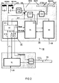
- a control device SE is therefore additionally provided in the trackside devices 10, 11, which comprises a control circuit 30 and a blocking element in the form of a diode D1.
- the control circuit 30 acts via a reset line 32 on a reset input of a telegram control circuit 34.
- the telegram control circuit 34 forms a telegram generator 36 together with a telegram memory 35 which is provided twice and can be interrogated for security reasons.
- the control device SE is preferably together with the other components, in particular the control circuit (50 kHz oscillating circuit) KK, the energy receiving circuit EE (100 kHz oscillating circuit) ), a voltage stabilization 38 arranged downstream thereof and the transmission device formed by a transmission amplifier SV and an antenna ANT SEN and the telegram generator 36 arranged in the track coupling coil GKS.
- the control circuit 50 kHz oscillating circuit
- the energy receiving circuit EE 100 kHz oscillating circuit
- a voltage stabilization 38 arranged downstream thereof and the transmission device formed by a transmission amplifier SV and an antenna ANT SEN and the telegram generator 36 arranged in the track coupling coil GKS.
- the transmission loop SS can be supplied with loop telegrams STEL via a transmission loop amplifier SSV and a control logic SL.
- the transmit loop amplifier SSV can be activated in a pulse-like manner with a predeterminable period, so that, for example, two data telegrams identified as loop telegrams STEL can be output, which the telegram generator 36 generates depending on the current signal term reported via line 28.
- the control circuit 30 In order to activate the transmission loop SS, the control circuit 30 also switches through the supply voltage U1b, which is taken from the signal lamp circuit and supplied via the line 29 to the control logic SL, for the telegram generation as the voltage U1 to the telegram generator 36.
- the control logic SL recognizes the end (tel.end) of a data telegram from the telegram generator 36 and can thus stop the delivery (until the beginning of the next period) after the desired number of loop telegrams to be output have been reached.
- the diode D1 decouples the supply voltage U1 from the supply branch (voltage stabilization 38) U1a for the transmitting device SEN, so that the transmitting amplifier SV remains inactive. As a result, the loop telegrams are output without simultaneous data telegram output from the track coupling coil.
- the track coupling coil is advantageously always ready for communication with a passing vehicle. If a vehicle with its vehicle coupling coil FZS (FIG. 1) applies energy to the energy receiving circuit EE (vehicle energy supply), the current data telegram DTEL supplied by the telegram generator 36 via an output line 40 is sent via the transmission amplifier SV.
- the control circuit 30 recognizes the vehicle power supply via a query line 42 (i.e. H. that a vehicle passes the track coupling coil GKS) and interrupts or prevents the further output of loop telegrams via a control line 44 until the vehicle drives past or a predetermined period of time has expired.
- FIG. 3 schematically shows the time delivery of loop telegrams STEL, wherein at time t o (start of transmission) only the header section, ie an incomplete loop telegram STELU, is initially output as the start step.
- an unchanged data telegram DTEL fed from the telegram generator 36 (FIG. 2) to the transmission loop amplifier SSV is terminated after the start part START has been sent. This can be achieved by briefly switching off the supply voltage U1b or (as shown explicitly in FIG. 2) by acting on the reset input of the telegram control circuit 34.
- the control device SE After a short transmission interruption of 0.15 ms, the control device SE ensures that a loop telegram STEL is now completely output by applying an unchanged data telegram DTEL to the transmission loop amplifier SSV via line 37.
- the bit structure of the loop telegram STEL essentially corresponds to the unchanged data telegram DTEL with the start part START already mentioned and a remainder part REST with a command section KOM, a code lock CD and a final stop step STOP.
- This loop telegram STEL can be sent out several times, preferably twice.
- the double start step is a significant marking that can be recognized by the vehicle computer FR.
Landscapes
- Engineering & Computer Science (AREA)
- Mechanical Engineering (AREA)
- Train Traffic Observation, Control, And Security (AREA)
Applications Claiming Priority (2)
| Application Number | Priority Date | Filing Date | Title |
|---|---|---|---|
| DE4437129A DE4437129C1 (de) | 1994-10-05 | 1994-10-05 | Streckenseitige Einrichtung zur Fahrzeugbeeinflussung |
| DE4437129 | 1994-10-05 |
Publications (2)
| Publication Number | Publication Date |
|---|---|
| EP0705751A1 true EP0705751A1 (fr) | 1996-04-10 |
| EP0705751B1 EP0705751B1 (fr) | 1998-03-25 |
Family
ID=6531010
Family Applications (1)
| Application Number | Title | Priority Date | Filing Date |
|---|---|---|---|
| EP95250239A Expired - Lifetime EP0705751B1 (fr) | 1994-10-05 | 1995-09-29 | Dispositif le long d'une voie ferrée pour le contrÔle d'un véhicule |
Country Status (3)
| Country | Link |
|---|---|
| EP (1) | EP0705751B1 (fr) |
| DE (2) | DE4437129C1 (fr) |
| DK (1) | DK0705751T3 (fr) |
Families Citing this family (2)
| Publication number | Priority date | Publication date | Assignee | Title |
|---|---|---|---|---|
| DE50012604D1 (de) * | 2000-07-12 | 2006-05-24 | Siemens Schweiz Ag Zuerich | Vorrichtung zum Übertragen eines Zustandssignals eines Verkehrsbeeinflussungsgeräts auf ein Fahrzeug |
| DE102009012986A1 (de) * | 2009-03-12 | 2010-09-23 | Siemens Aktiengesellschaft | Verfahren zum Betreiben einer Zugbeeinflussungseinrichtung, streckenseitige elektonische Einheit und Balise für eine Zugbeeinflussungseinrichtung sowie Zugbeeinflussungseinrichtung |
Citations (4)
| Publication number | Priority date | Publication date | Assignee | Title |
|---|---|---|---|---|
| DE2710113A1 (de) * | 1977-03-04 | 1978-09-07 | Licentia Gmbh | Verfahren zur ueberwachung des verkehrs von zuegen |
| DE3106629A1 (de) * | 1981-02-23 | 1982-09-09 | Siemens AG, 1000 Berlin und 8000 München | Einrichtung zur punktfoermigen zugbeeinflussung |
| DE3131246A1 (de) * | 1981-08-04 | 1983-02-24 | Licentia Patent-Verwaltungs-Gmbh, 6000 Frankfurt | Induktive datenuebertragung zwischen fahrzeugen und streckenfesten einrichtungen |
| DE3116372A1 (de) * | 1981-04-18 | 1983-03-10 | Licentia Patent-Verwaltungs-Gmbh, 6000 Frankfurt | Induktive datenuebertragung zwischen fahrzeugen und streckenfesten einrichtungen |
-
1994
- 1994-10-05 DE DE4437129A patent/DE4437129C1/de not_active Expired - Fee Related
-
1995
- 1995-09-29 DK DK95250239T patent/DK0705751T3/da active
- 1995-09-29 EP EP95250239A patent/EP0705751B1/fr not_active Expired - Lifetime
- 1995-09-29 DE DE59501694T patent/DE59501694D1/de not_active Expired - Fee Related
Patent Citations (4)
| Publication number | Priority date | Publication date | Assignee | Title |
|---|---|---|---|---|
| DE2710113A1 (de) * | 1977-03-04 | 1978-09-07 | Licentia Gmbh | Verfahren zur ueberwachung des verkehrs von zuegen |
| DE3106629A1 (de) * | 1981-02-23 | 1982-09-09 | Siemens AG, 1000 Berlin und 8000 München | Einrichtung zur punktfoermigen zugbeeinflussung |
| DE3116372A1 (de) * | 1981-04-18 | 1983-03-10 | Licentia Patent-Verwaltungs-Gmbh, 6000 Frankfurt | Induktive datenuebertragung zwischen fahrzeugen und streckenfesten einrichtungen |
| DE3131246A1 (de) * | 1981-08-04 | 1983-02-24 | Licentia Patent-Verwaltungs-Gmbh, 6000 Frankfurt | Induktive datenuebertragung zwischen fahrzeugen und streckenfesten einrichtungen |
Non-Patent Citations (1)
| Title |
|---|
| HOHMANN H: "PUNKT- UND LINIENFÖRMIGE ÜBERTRAGUNG FÜR ATC BEI DEN DÄNISCHEN STAATSBAHNEN", ELEKTRISCHE BAHNEN, NOV. 1991, GERMANY, vol. 89, no. 11, ISSN 0013-5437, pages 468 - 470 * |
Also Published As
| Publication number | Publication date |
|---|---|
| DK0705751T3 (da) | 1999-01-11 |
| EP0705751B1 (fr) | 1998-03-25 |
| DE59501694D1 (de) | 1998-04-30 |
| DE4437129C1 (de) | 1996-02-01 |
Similar Documents
| Publication | Publication Date | Title |
|---|---|---|
| DE3040137C2 (de) | Punktförmige Einrichtung zur Übertragung von Information zwischen einer Trasse und auf dieser geführten Fahrzeugen | |
| AT393657B (de) | Verfahren zur uebertragung von informationen und/oder befehlen | |
| DE2628905C3 (de) | Zugsicherungs- und -Steuerungsanlage | |
| DE2215442A1 (de) | Fahrzeugsteuerungssystem | |
| EP0424664B1 (fr) | Dispositif pour la transmission d'information de commande à un véhicule ferroviaire | |
| EP4079594A1 (fr) | Dispositif de surveillance pour un système ferroviaire | |
| EP0705751B1 (fr) | Dispositif le long d'une voie ferrée pour le contrÔle d'un véhicule | |
| DE2628942B1 (de) | Zugsicherungs- und -steuerungsanlage | |
| DE3106629A1 (de) | Einrichtung zur punktfoermigen zugbeeinflussung | |
| EP2069183B1 (fr) | Dispositif permutable sécurisé pour recevoir et/ou émettre des signaux destinés à commander un train sur un véhicule ferroviaire | |
| DE1804225A1 (de) | Anordnung zur UEbertragung von Signalen fuer die Steuerung der Fahrt eines Fahrzeuges laengs eines Gleises | |
| EP0705752B1 (fr) | Procédé pour la transmission d'informations d'une section de voie vers un véhicule et dispositif le long de la voie pour la mise en oeuvre de ce procédé | |
| DE3047637A1 (de) | Zugsicherungseinrichtung | |
| DE2223413B2 (de) | Steuereinrichtung fuer fahrzeuge | |
| DE2205368C3 (de) | Einrichtung zur punktweisen Zugbeeinflussung und Informationsübertragung zwischen Schienenfahrzeugen und der Strecke | |
| EP1561663A1 (fr) | Système et méthode de contrôle de l' intégrité des trains | |
| EP0535549B1 (fr) | Système de transmission inductive d'information de contrôle sur des véhicules ferroviaires | |
| DE4232919A1 (de) | Verfahren zum Bestimmen der Position eines Fahrzeugs auf einer Fahrstrecke | |
| WO1995033642A1 (fr) | Dispositif de commande automatique des trains | |
| DE1530357B2 (de) | Verfahren zur einstellung einer weiche oder der simultanen einstellung mehrerer weichen vom fahrzeug aus | |
| DE2327689C2 (de) | Besetztmeldeeinrichtung für Gleisabschnitte in Eisenbahnanlagen | |
| AT242192B (de) | Zugsicherungssystem mit linienförmiger Signalübertragung zwischen Zug und Strecke | |
| WO1995033641A1 (fr) | Dispositif de commande automatique de trains | |
| DE2643134A1 (de) | Steuereinrichtung zum einstellen und sichern von fahrwegen des spurgebundenen landverkehrs | |
| DE9421292U1 (de) | Streckenkoppelgerät |
Legal Events
| Date | Code | Title | Description |
|---|---|---|---|
| PUAI | Public reference made under article 153(3) epc to a published international application that has entered the european phase |
Free format text: ORIGINAL CODE: 0009012 |
|
| AK | Designated contracting states |
Kind code of ref document: A1 Designated state(s): CH DE DK IT LI NL SE |
|
| 17P | Request for examination filed |
Effective date: 19960620 |
|
| GRAG | Despatch of communication of intention to grant |
Free format text: ORIGINAL CODE: EPIDOS AGRA |
|
| GRAG | Despatch of communication of intention to grant |
Free format text: ORIGINAL CODE: EPIDOS AGRA |
|
| GRAH | Despatch of communication of intention to grant a patent |
Free format text: ORIGINAL CODE: EPIDOS IGRA |
|
| 17Q | First examination report despatched |
Effective date: 19970902 |
|
| GRAH | Despatch of communication of intention to grant a patent |
Free format text: ORIGINAL CODE: EPIDOS IGRA |
|
| GRAA | (expected) grant |
Free format text: ORIGINAL CODE: 0009210 |
|
| AK | Designated contracting states |
Kind code of ref document: B1 Designated state(s): CH DE DK IT LI NL SE |
|
| REG | Reference to a national code |
Ref country code: CH Ref legal event code: EP |
|
| REG | Reference to a national code |
Ref country code: CH Ref legal event code: NV Representative=s name: SIEMENS SCHWEIZ AG |
|
| REF | Corresponds to: |
Ref document number: 59501694 Country of ref document: DE Date of ref document: 19980430 |
|
| ITF | It: translation for a ep patent filed | ||
| REG | Reference to a national code |
Ref country code: DK Ref legal event code: T3 |
|
| PLBE | No opposition filed within time limit |
Free format text: ORIGINAL CODE: 0009261 |
|
| STAA | Information on the status of an ep patent application or granted ep patent |
Free format text: STATUS: NO OPPOSITION FILED WITHIN TIME LIMIT |
|
| 26N | No opposition filed | ||
| PGFP | Annual fee paid to national office [announced via postgrant information from national office to epo] |
Ref country code: NL Payment date: 20020926 Year of fee payment: 8 |
|
| PG25 | Lapsed in a contracting state [announced via postgrant information from national office to epo] |
Ref country code: NL Free format text: LAPSE BECAUSE OF NON-PAYMENT OF DUE FEES Effective date: 20040401 |
|
| NLV4 | Nl: lapsed or anulled due to non-payment of the annual fee |
Effective date: 20040401 |
|
| PGFP | Annual fee paid to national office [announced via postgrant information from national office to epo] |
Ref country code: DK Payment date: 20080909 Year of fee payment: 14 |
|
| PGFP | Annual fee paid to national office [announced via postgrant information from national office to epo] |
Ref country code: IT Payment date: 20080924 Year of fee payment: 14 |
|
| PGFP | Annual fee paid to national office [announced via postgrant information from national office to epo] |
Ref country code: DE Payment date: 20081121 Year of fee payment: 14 Ref country code: CH Payment date: 20081211 Year of fee payment: 14 |
|
| PGFP | Annual fee paid to national office [announced via postgrant information from national office to epo] |
Ref country code: SE Payment date: 20080909 Year of fee payment: 14 |
|
| REG | Reference to a national code |
Ref country code: CH Ref legal event code: PCAR Free format text: SIEMENS SCHWEIZ AG;INTELLECTUAL PROPERTY FREILAGERSTRASSE 40;8047 ZUERICH (CH) |
|
| REG | Reference to a national code |
Ref country code: CH Ref legal event code: PL |
|
| EUG | Se: european patent has lapsed | ||
| REG | Reference to a national code |
Ref country code: DK Ref legal event code: EBP |
|
| PG25 | Lapsed in a contracting state [announced via postgrant information from national office to epo] |
Ref country code: DE Free format text: LAPSE BECAUSE OF NON-PAYMENT OF DUE FEES Effective date: 20100401 |
|
| PG25 | Lapsed in a contracting state [announced via postgrant information from national office to epo] |
Ref country code: LI Free format text: LAPSE BECAUSE OF NON-PAYMENT OF DUE FEES Effective date: 20090930 Ref country code: CH Free format text: LAPSE BECAUSE OF NON-PAYMENT OF DUE FEES Effective date: 20090930 |
|
| PG25 | Lapsed in a contracting state [announced via postgrant information from national office to epo] |
Ref country code: DK Free format text: LAPSE BECAUSE OF NON-PAYMENT OF DUE FEES Effective date: 20090930 |
|
| PG25 | Lapsed in a contracting state [announced via postgrant information from national office to epo] |
Ref country code: IT Free format text: LAPSE BECAUSE OF NON-PAYMENT OF DUE FEES Effective date: 20090929 |
|
| PG25 | Lapsed in a contracting state [announced via postgrant information from national office to epo] |
Ref country code: SE Free format text: LAPSE BECAUSE OF NON-PAYMENT OF DUE FEES Effective date: 20090930 |