EP0705641B1 - Mixer for foaming pasty substances - Google Patents
Mixer for foaming pasty substances Download PDFInfo
- Publication number
- EP0705641B1 EP0705641B1 EP95115610A EP95115610A EP0705641B1 EP 0705641 B1 EP0705641 B1 EP 0705641B1 EP 95115610 A EP95115610 A EP 95115610A EP 95115610 A EP95115610 A EP 95115610A EP 0705641 B1 EP0705641 B1 EP 0705641B1
- Authority
- EP
- European Patent Office
- Prior art keywords
- chamber
- mixing
- disc
- sub
- disposed
- Prior art date
- Legal status (The legal status is an assumption and is not a legal conclusion. Google has not performed a legal analysis and makes no representation as to the accuracy of the status listed.)
- Expired - Lifetime
Links
Images
Classifications
-
- B—PERFORMING OPERATIONS; TRANSPORTING
- B28—WORKING CEMENT, CLAY, OR STONE
- B28C—PREPARING CLAY; PRODUCING MIXTURES CONTAINING CLAY OR CEMENTITIOUS MATERIAL, e.g. PLASTER
- B28C5/00—Apparatus or methods for producing mixtures of cement with other substances, e.g. slurries, mortars, porous or fibrous compositions
- B28C5/38—Apparatus or methods for producing mixtures of cement with other substances, e.g. slurries, mortars, porous or fibrous compositions wherein the mixing is effected both by the action of a fluid and by directly-acting driven mechanical means, e.g. stirring means ; Producing cellular concrete
- B28C5/381—Producing cellular concrete
- B28C5/383—Producing cellular concrete comprising stirrers to effect the mixing
-
- B—PERFORMING OPERATIONS; TRANSPORTING
- B01—PHYSICAL OR CHEMICAL PROCESSES OR APPARATUS IN GENERAL
- B01F—MIXING, e.g. DISSOLVING, EMULSIFYING OR DISPERSING
- B01F27/00—Mixers with rotary stirring devices in fixed receptacles; Kneaders
- B01F27/80—Mixers with rotary stirring devices in fixed receptacles; Kneaders with stirrers rotating about a substantially vertical axis
- B01F27/87—Mixers with rotary stirring devices in fixed receptacles; Kneaders with stirrers rotating about a substantially vertical axis the receptacle being divided into superimposed compartments
-
- B—PERFORMING OPERATIONS; TRANSPORTING
- B29—WORKING OF PLASTICS; WORKING OF SUBSTANCES IN A PLASTIC STATE IN GENERAL
- B29B—PREPARATION OR PRETREATMENT OF THE MATERIAL TO BE SHAPED; MAKING GRANULES OR PREFORMS; RECOVERY OF PLASTICS OR OTHER CONSTITUENTS OF WASTE MATERIAL CONTAINING PLASTICS
- B29B7/00—Mixing; Kneading
- B29B7/74—Mixing; Kneading using other mixers or combinations of mixers, e.g. of dissimilar mixers ; Plant
- B29B7/7404—Mixing devices specially adapted for foamable substances
- B29B7/7409—Mixing devices specially adapted for foamable substances with supply of gas
- B29B7/7414—Mixing devices specially adapted for foamable substances with supply of gas with rotatable stirrer, e.g. using an intermeshing rotor-stator system
Definitions
- the invention relates to a mixing device for foaming pasty substances, with a rotationally symmetrical mixing chamber and a mixer arranged in it, with one in the longitudinal axis arranged shaft.
- Mixing devices of the generic type are used for foaming of various pasty substances, especially those that later by cooling or by chemical reactions harden and trap air bubbles.
- various building materials such as mortar treated to by the enclosed air bubbles achieve better insulation and lower weight.
- Chocolate pastes are also used in the food industry, for example foamed to a larger size with the same dimensions Generate volume.
- the known mixing devices have a cylindrical housing on, in which a mixer is arranged, which consists of a driven Shaft with wings arranged thereon. At the bottom Part of the housing is usually a compressed air connection.
- a mixing device is made with a mixture of the foamable pasty substance, for example cement, and a filled with foam-forming, surface-active agent. After mixing the mixing chamber must be emptied.
- This discontinuous Working method leads to an inhomogeneous distribution the air bubbles in the material to be foamed, on the other hand, those in the Throughputs to be achieved on an industrial scale per mixing device unsatisfactory.
- the invention is therefore based on the object of a continuous to create working mixer, in which both the Throughput performance as well as homogeneity and degree of ventilation of the foamed material are improved.
- the solution to the problem is with a generic mixing device characterized in that the mixing chamber on the shaft dividing into a first and a second partial chamber Disk is arranged, the diameter of which is such that between the circumference of the disc and the wall of the mixing chamber an annular gap remains that the first sub-chamber has an inlet connection for a surface-active agent and a compressed air connection has, and that the second chamber at least one feed and Drain for a continuous flow of foamable Has fabric.
- a continuous mass flow flows through the second sub-chamber of pasty substance to be foamed.
- the longitudinal axis of the mixing chamber vertical and the second sub-chamber above the first arranged.
- the size of the annular gap between the disc and the housing of the Mixing chamber arises on the one hand from the need to prevent the heavier pasty substance to be foamed underneath the effect of gravity in the first foaming Chamber penetrates, but that on the other hand, the passage of the fine-pored foam in the second compartment, where it with the foam Substance to be mixed under the influence of Compressed air must be made possible.
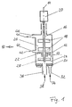
- a mixing device 10 consists of a Mixing chamber 12, which is the basic geometric shape of a cylinder having.
- a drive shaft 16 is arranged in the longitudinal axis 14, the mixing blades 18 carries and so forms a mixer.
- the Shaft 16 is driven by an electric motor 20.
- On the Shaft 16 is also a disc 22 is arranged, the mixing chamber 12 leaving an annular gap a in a first, lower sub-chamber 24 and a second, upper sub-chamber 26 divided.
- Mixing vanes are also in the lower sub-chamber 24 28 arranged on the shaft 16.
- a filter 30 is arranged through a compressed air connection 32 can be pressurized with compressed air.
- the through the compressed air connection 32 incoming compressed air 34 is through the filter 30 finely distributed and flows over the entire cross-sectional area of the Filters 30 and thus the entire bottom surface of the mixing chamber 12 out.
- the rotating mixing blades 28 cause together with the inflowing compressed air 34 strong foam formation in the first partial chamber 24, which otherwise is free of other substances.
- the area of the Annular gap a is between 3 and 15% of the cross-sectional area the mixing chamber 12.
- a nozzle is located directly above the radial plane of the disk 22 40 arranged as an inflow for the foamed pasty substance 42.
- the supplied substance 42 leaves via a drain connection 44 the upper, second mixing chamber 26.
- the rotation of the mixer 16/18 creates a field of centrifugal forces generates the incoming mass flow of pasty, substance to be mixed against the wall of the upper chamber 26 presses.
- the foam mixture entering through the annular gap a increases under the pressure generated by the compressed air 34 on the wall the mixing chamber 12 and is then pushed outwards by the heavier material particles of the pasty to be mixed Fabric pressed inwards.
Abstract
Description
Die Erfindung betrifft eine Mischvorrichtung zum Aufschäumen von pastösen Stoffen, mit einer rotationssymmetrischen Mischkammer und einem darin angeordneten Mischwerk, mit einer in der Längsachse angeordneten Welle.The invention relates to a mixing device for foaming pasty substances, with a rotationally symmetrical mixing chamber and a mixer arranged in it, with one in the longitudinal axis arranged shaft.
Mischvorrichtungen der gattungsgemäßen Art werden zum Aufschäumen von verschiedenen pastösen Stoffen verwendet, insbesondere solchen, die später durch Abkühlen oder durch chemische Reaktionen erhärten und dabei Luftblasen einschließen. So werden beispielsweise verschiedene Baumaterialien, wie beispielsweise Mörtel, dergestalt behandelt, um durch die eingeschlossenen Luftblasen eine bessere Isolationsfähigkeit und geringeres Gewicht zu erreichen. Auch in der Nahrungsmittel-Industrie werden beispielsweise Schokoladenpasten aufgeschäumt, um bei gleicher Masse ein optisch größeres Volumen zu erzeugen. Mixing devices of the generic type are used for foaming of various pasty substances, especially those that later by cooling or by chemical reactions harden and trap air bubbles. For example various building materials such as mortar treated to by the enclosed air bubbles achieve better insulation and lower weight. Chocolate pastes are also used in the food industry, for example foamed to a larger size with the same dimensions Generate volume.
Die bekannten Mischvorrichtungen weisen ein zylindrisches Gehäuse auf, in dem ein Mischwerk angeordnet ist, das aus einer angetriebenen Welle mit daran angeordneten Flügeln besteht. Im unteren Teil des Gehäuses ist üblicherweise ein Druckluftanschluß angeordnet. Eine solche Mischvorrichtung wird mit einer Mischung aus dem aufzuschäumenden pastösen Stoff, beispielsweise Zement, und einem schaumbildenden, oberflächenaktiven Agens befüllt. Nach Durchmischung muß die Mischkammer entleert werden. Diese diskontinuierliche Arbeitsweise führt zum einen zu einer inhomogenen Verteilung der Luftblasen im aufzuschäumenden Stoff, andererseits sind die im industriellen Maßstab zu erzielenden Durchsätze pro Mischvorrichtung unbefriedigend.The known mixing devices have a cylindrical housing on, in which a mixer is arranged, which consists of a driven Shaft with wings arranged thereon. At the bottom Part of the housing is usually a compressed air connection. Such a mixing device is made with a mixture of the foamable pasty substance, for example cement, and a filled with foam-forming, surface-active agent. After mixing the mixing chamber must be emptied. This discontinuous Working method leads to an inhomogeneous distribution the air bubbles in the material to be foamed, on the other hand, those in the Throughputs to be achieved on an industrial scale per mixing device unsatisfactory.
Der Erfindung liegt daher die Aufgabe zugrunde, eine kontinuierlich arbeitende Mischvorrichtung zu schaffen, bei der sowohl die Durchsatzleistung wie auch die Homogenität und der Belüftungsgrad des aufgeschäumten Stoffes verbessert sind.The invention is therefore based on the object of a continuous to create working mixer, in which both the Throughput performance as well as homogeneity and degree of ventilation of the foamed material are improved.
Die Lösung der Aufgabe ist bei einer gattungsgemäßen Mischvorrichtung dadurch gekennzeichnet, daß auf der Welle eine die Mischkammer in eine erste und eine zweite Teilkammer unterteilende Scheibe angeordnet ist, deren Durchmesser so bemessen ist, daß zwischen dem Umfang der Scheibe und der Wandung der Mischkammer ein Ringspalt verbleibt, daß die erste Teilkammer einen Zuflußstutzen für ein oberflächenaktives Agens und einen Druckluftanschluß aufweist, und daß die zweite Kammer zumindest je einen Zu- und Abfluß für einen kontinuierlichen Durchsatz an aufzuschäumendem Stoff aufweist.The solution to the problem is with a generic mixing device characterized in that the mixing chamber on the shaft dividing into a first and a second partial chamber Disk is arranged, the diameter of which is such that between the circumference of the disc and the wall of the mixing chamber an annular gap remains that the first sub-chamber has an inlet connection for a surface-active agent and a compressed air connection has, and that the second chamber at least one feed and Drain for a continuous flow of foamable Has fabric.
Bei der so geschaffenen Vorrichtung wird in der ersten Teilkammer kontinuierlich Schaum erzeugt, der aufgrund des von der Druckluft in der Kammer erzeugten Überdruckes durch den Ringspalt zwischen dem Umfang der Scheibe und der Wandung der Mischkammer in die zweite Teilkammer gedrückt wird.In the device created in this way, in the first subchamber continuously creates foam due to the from the compressed air generated overpressure in the chamber through the annular gap between the circumference of the disc and the wall of the mixing chamber in the second compartment is pressed.
Durch die zweite Teilkammer fließt ein kontinuierlicher Massenstrom an aufzuschäumendem pastösen Stoff. Unter dem Einfluß des in der zweiten Teilkammer rotierenden Mischwerkes werden der aufzuschäumende pastöse Stoff und der in der ersten Teilkammer erzeugte Schaum vermischt und in eine Rotationsbewegung versetzt. Wegen der auftretenden Zentrifugalkräfte wird der aufzuschäumende pastöse Stoff nach außen an die Wandung der Mischkammer gedrückt, während der leichtere Schaum zur Mitte verdrängt wird.A continuous mass flow flows through the second sub-chamber of pasty substance to be foamed. Under the influence of the in the second sub-chamber of the rotating mixer are the ones to be foamed pasty substance and the one produced in the first subchamber Foam mixed and rotated. Because of the centrifugal forces that occur become the pasty to be foamed While pressing fabric outwards against the wall of the mixing chamber the lighter foam is displaced towards the middle.
Durch das Zusammenwirken von zwei Effekten - der unmittelbaren Einwirkung der Mischflügel des Mischwerks einerseits und der durch die Zentrifugalkräfte erzeugten Bewegung des Schaums über den gesamten Querschnitt der Teilkammer andererseits - wird eine gleichmäßige Verteilung der kleinen Luftbläschen im gesamten aufzuschäumenden Stoff gewährleistet.By the interaction of two effects - the immediate one Influence of the mixing blades of the mixer on the one hand and by the centrifugal forces generated movement of the foam all over Cross-section of the sub-chamber on the other hand - becomes an even one Distribution of the small air bubbles throughout the foam Fabric guaranteed.
In einer bevorzugten Ausführungsform ist die Längsachse der Mischkammer senkrecht und die zweite Teilkammer oberhalb der ersten angeordnet.In a preferred embodiment, the longitudinal axis of the mixing chamber vertical and the second sub-chamber above the first arranged.
Die Größe des Ringspalts zwischen der Scheibe und dem Gehäuse der Mischkammer ergibt sich einerseits durch die Notwendigkeit, zu verhindern, daß der schwerere zu verschäumende pastöse Stoff unter der Wirkung der Schwerkraft in die der Schaumbildung dienende erste Kammer eindringt, daß aber andererseits der Durchtritt des feinporigen Schaums in die zweite Teilkammer, wo er mit dem aufzuschäumenden Stoff vermischt werden soll, unter dem Einfluß der Druckluft ermöglicht werden muß.The size of the annular gap between the disc and the housing of the Mixing chamber arises on the one hand from the need to prevent the heavier pasty substance to be foamed underneath the effect of gravity in the first foaming Chamber penetrates, but that on the other hand, the passage of the fine-pored foam in the second compartment, where it with the foam Substance to be mixed under the influence of Compressed air must be made possible.
Bei Experimenten hat sich herausgestellt, daß eine Größe des Ringspalts zwischen 3 und 15 % der gesamten Querschnittsfläche der Mischkammer in der gleichen Radialebene, d.h. in der Radialebene der Scheibe, zu guten Ergebnissen führt.Experiments have shown that a size of the annular gap between 3 and 15% of the total cross-sectional area of the Mixing chamber in the same radial plane, i.e. in the radial plane the disc leads to good results.
Bei mit einem Prototyp gemäß der Erfindung ausgeführten Versuchen gelang es, belüfteten (porisierten) Mörtel herzustellen, dessen mittlere Dichte um 25 bis 30 % geringer war, als von Mörtel, der mit Vorrichtungen gemäß dem Stand der Technik hergestellt war. Die Homogenität in bezug auf die Dichte konnte um 7 bis 10 %, die Homogenität in bezug auf die Festigkeit um 8 bis 10 % erhöht werden, wobei die Produktionsleistung wegen des erstmals ermöglichten kontinuierlichen Betriebes deutlich erhöht war.In tests carried out with a prototype according to the invention managed to produce aerated (porized) mortar, the average density was 25 to 30% lower than that of mortar was made with devices according to the prior art. The Homogeneity in terms of density could be around 7 to 10%, the homogeneity increase in strength by 8 to 10%, whereby the production output because of the continuous made possible for the first time Operation was significantly increased.
Die Erfindung wird im folgenden unter Bezugnahme auf ein in der Zeichnung dargestelltes Ausführungsbeispiel näher erläutert. Die einzige Figur der Zeichnung zeigt einen Längsschnitt durch eine erfindungsgemäße Mischvorrichtung.The invention is described below with reference to an in the Drawing illustrated embodiment explained in more detail. The only figure of the drawing shows a longitudinal section through a mixing device according to the invention.
Eine erfindungsgemäße Mischvorrichtung 10 besteht aus einer
Mischkammer 12, die die geometrische Grundform eines Zylinders
aufweist. In der Längsachse 14 ist eine Antriebswelle 16 angeordnet,
die Mischflügel 18 trägt und so ein Mischwerk bildet. Die
Welle 16 wird durch einen Elektromotor 20 angetrieben. Auf der
Welle 16 ist weiterhin eine Scheibe 22 angeordnet, die die Mischkammer
12 unter Belassung eines ringförmigen Spaltes a in eine
erste, untere Teilkammer 24 und eine zweite, obere Teilkammer 26
unterteilt. In der unteren Teilkammer 24 sind ebenfalls Mischflügel
28 auf der Welle 16 angeordnet. Am Boden der ersten Teilkammer
24 ist ein Filter 30 angeordnet, der durch einen Druckluftanschluß
32 mit Druckluft beaufschlagt werden kann. Die durch den Druckluftanschluß
32 einströmende Druckluft 34 wird durch den Filter 30
fein verteilt und strömt auf der gesamten Querschnittsfläche des
Filters 30 und damit der gesamten Bodenfläche der Mischkammer 12
aus. Durch einen Anschlußstutzen 36 wird ein oberflächenaktives,
d.h. schaumbildendes Agens 38 zugeführt. Die rotierenden Mischflügel
28 bewirken zusammen mit der einströmenden Druckluft 34 eine
starke Schaumbildung in der ersten Teilkammer 24, die ansonsten
frei von anderen Stoffen ist.A mixing device 10 according to the invention consists of a
Unter dem durch die Druckluft 34 aufgebauten Innendruck wird der
erzeugte Schaum durch den Ringspalt a gepreßt. Die Fläche des
Ringspalts a beträgt zwischen 3 und 15 % der Querschnittsfläche
der Mischkammer 12.Under the internal pressure built up by the
Unmittelbar oberhalb der Radialebene der Scheibe 22 ist ein Stutzen
40 als Zufluß für den aufzuschäumenden pastösen Stoff 42 angeordnet.
Der zugeführte Stoff 42 verläßt über einen Abflußstutzen
44 die obere, zweite Mischkammer 26.A nozzle is located directly above the radial plane of the
Durch die Rotation des Mischwerks 16/18 wird ein Feld von Zentrifugalkräften
erzeugt, das den eintretenden Massenstrom an pastösem,
zu vermischendem Stoff gegen die Wandung der oberen Kammer 26
drückt. Das durch den Ringspalt a eintretende Schaumgemisch steigt
unter dem durch die Druckluft 34 erzeugten Druck an der Wandung
der Mischkammer 12 empor und wird sodann durch die nach außen gedrückten,
schwereren Stoffteilchen des zu vermischenden, pastösen
Stoffes nach innen gedrückt.The rotation of the
Durch das Zusammenwirken mit den rotierenden Mischflügeln 18 wird
so eine innige Vermischung von pastösem Stoff 42 und Schaum/Luftgemisch
bewirkt, so daß der aus dem Abflußstutzen 44 austretende
Massenstrom 46 einen hohen Anteil an homogen verteilten Luftblasen
enthält.By interacting with the rotating
Bei Versuchen mit aeriertem Zement wurden im Vergleich zu bekannten
Anlagen folgende besseren Werte erzielt:
Fu/ro Fu / ro
- 1010th
- MischvorrichtungMixing device
- 1212th
- MischkammerMixing chamber
- 1414
- Längsachse (von 12)Longitudinal axis (from 12)
- 1616
- Wellewave
- 1818th
- MischflügelMixing blades
- 2020th
- ElektromotorElectric motor
- 2222
- Scheibedisc
- 2424th
- untere, erste Teilkammerlower, first subchamber
- 2626
- obere, zweite Teilkammerupper, second compartment
- 2828
- MischflügelMixing blades
- 3030th
- Filterfilter
- 3232
- DruckluftanschlußCompressed air connection
- 3434
- DruckluftCompressed air
- 3636
- Zuflußstutzen (für 38)Inflow nozzle (for 38)
- 3838
- oberflächenaktives Agenssurface active agent
- 4040
- Zufluß (für 42)Inflow (for 42)
- 4242
- aufzuschäumender pastöser Stoffpasty substance to be foamed
- 4444
- Abfluß (für 46)Drain (for 46)
- 4646
- aufgeschäumter pastöser Stofffoamed pasty substance
- aa
- Ringspalt (zwischen 22 und 12)Annular gap (between 22 and 12)
Fu/roFu / ro
Claims (7)
- Mixer for foaming pasty substances, with a rotationally symmetrical mixing chamber (12) and a mixing unit (16/18) which is disposed in the latter and comprises a shaft (16) disposed along the longitudinal axis (14), characterised in that a disc (22), which divides the mixing chamber into a first (24) and a second sub-chamber (26), is disposed on the shaft (16), the diameter of which disc is of a dimension such that an annular gap (a) remains between the circumference of the disc and the wall of the mixing chamber, that the first sub-chamber (24) comprises an inlet connection piece (36) for a surfactant (38) and a compressed-air connection (32), and that the second chamber (26) comprises at least one inlet and one outlet (40/44) for a continuous throughput of substance (42/46) to be foamed.
- Mixer according to claim 1, characterised in that the longitudinal axis (14) is perpendicular and the second chamber (26) is disposed above the first chamber (24).
- Mixer according to claim 2, characterised in that the inlet (40), of which there is at least one, for the substance (42) to be foamed lies in a radial plane disposed directly above the disc (22).
- Mixer according to one of the preceding claims, characterised in that the inlet connection piece (36) for the surfactant (38) is disposed in the bottom of the first sub-chamber (24).
- Mixer according to one of the preceding claims, characterised in that a filter (30), which disperses the compressed air (34), is disposed in the bottom of the first chamber (24).
- Mixer according to one of the preceding claims, characterised in that the area of the annular gap (a) constitutes 3 to 15% of the cross-sectional area of the mixing chamber (12) in the radial plane of the disc (22).
- Mixer according to one of the preceding claims, characterised in that the shaft (16) of the mixing unit bears mixing blades (18/28) both in the first sub-chamber (24) and in the second sub-chamber (26).
Applications Claiming Priority (2)
| Application Number | Priority Date | Filing Date | Title |
|---|---|---|---|
| RU9494037503A RU2077421C1 (en) | 1994-10-06 | 1994-10-06 | Device for aeration of mortar |
| RU94037503 | 1994-10-06 |
Publications (3)
| Publication Number | Publication Date |
|---|---|
| EP0705641A2 EP0705641A2 (en) | 1996-04-10 |
| EP0705641A3 EP0705641A3 (en) | 1996-06-19 |
| EP0705641B1 true EP0705641B1 (en) | 1998-01-07 |
Family
ID=20161375
Family Applications (1)
| Application Number | Title | Priority Date | Filing Date |
|---|---|---|---|
| EP95115610A Expired - Lifetime EP0705641B1 (en) | 1994-10-06 | 1995-10-04 | Mixer for foaming pasty substances |
Country Status (5)
| Country | Link |
|---|---|
| EP (1) | EP0705641B1 (en) |
| AT (1) | ATE161752T1 (en) |
| DE (1) | DE59501211D1 (en) |
| ES (1) | ES2114261T3 (en) |
| RU (1) | RU2077421C1 (en) |
Families Citing this family (4)
| Publication number | Priority date | Publication date | Assignee | Title |
|---|---|---|---|---|
| DE10157726A1 (en) * | 2001-11-24 | 2003-06-05 | Krauss Maffei Kunststofftech | Gas loading unit of a polyurethane injection molding machine |
| US6935769B2 (en) * | 2002-02-06 | 2005-08-30 | Cargill Limited | Apparatus for production of striated, laminated lipid-based confections |
| RU2586692C1 (en) * | 2014-12-31 | 2016-06-10 | Федеральное государственное бюджетное образовательное учреждение высшего профессионального образования "Российский химико-технологический университет имени Д.И. Менделеева (РХТУ им. Д.И. Менделеева)" | Mixer-aerator for liquid-phase streams |
| CN114272796A (en) * | 2021-11-24 | 2022-04-05 | 太仓北新建材有限公司 | Foaming system of multi-type foaming agent and compounding control method |
Family Cites Families (4)
| Publication number | Priority date | Publication date | Assignee | Title |
|---|---|---|---|---|
| CH319589A (en) * | 1953-03-12 | 1957-02-28 | Spumalit Anstalt | Device for the continuous production of curable foam |
| FR2128424A1 (en) * | 1971-03-02 | 1972-10-20 | Dynamit Nobel Ag | Phenolic foam sheets prodn - by supplying mixt of liquid phenolic resin, blowing agent and curing agent into heated double bel |
| SU887202A1 (en) * | 1979-06-20 | 1981-12-07 | Киевский Завод Строительных Материалов | Continuous-action ajitator for preparing gypsum mixtures |
| SU903132A1 (en) * | 1979-07-23 | 1982-02-07 | Государственный Научно-Исследовательский Институт Строительных Материалов И Изделий | Mixer for preparing gypsum mixes |
-
1994
- 1994-10-06 RU RU9494037503A patent/RU2077421C1/en active
-
1995
- 1995-10-04 EP EP95115610A patent/EP0705641B1/en not_active Expired - Lifetime
- 1995-10-04 AT AT95115610T patent/ATE161752T1/en not_active IP Right Cessation
- 1995-10-04 ES ES95115610T patent/ES2114261T3/en not_active Expired - Lifetime
- 1995-10-04 DE DE59501211T patent/DE59501211D1/en not_active Expired - Fee Related
Also Published As
| Publication number | Publication date |
|---|---|
| RU94037503A (en) | 1996-05-27 |
| RU2077421C1 (en) | 1997-04-20 |
| ES2114261T3 (en) | 1998-05-16 |
| DE59501211D1 (en) | 1998-02-12 |
| ATE161752T1 (en) | 1998-01-15 |
| EP0705641A2 (en) | 1996-04-10 |
| EP0705641A3 (en) | 1996-06-19 |
Similar Documents
| Publication | Publication Date | Title |
|---|---|---|
| DE10204921C1 (en) | Dispersing apparatus | |
| DE2437231C3 (en) | Device for producing an air-entrained mortar | |
| CH657844A5 (en) | METHOD AND DEVICE FOR PRODUCING FOAMED MIXTURES. | |
| CH686229A5 (en) | Method and apparatus for continuous networks of grain and use the network device. | |
| DE2158966A1 (en) | Mixing device | |
| DE2450976A1 (en) | PROCEDURE OR DEVICE FOR MIXING AND / OR GRANULATING POWDER ORGANIC GRILLED SUBSTANCES WITH AT LEAST ONE LIQUID | |
| EP0705641B1 (en) | Mixer for foaming pasty substances | |
| DE10354888B4 (en) | Colloidal mixer and process for the colloidal treatment of a mixture | |
| EP0158358A2 (en) | Device for dispersing and/or emulsification of a mixture consisting of at least two materials | |
| CH342549A (en) | Hollow stirrer for stirring at least one fluid into a liquid | |
| DE927006C (en) | Method and device for the production of a finely machined chocolate mass | |
| DE2108181A1 (en) | Method and device for the continuous processing of granular material, for example foundry sand | |
| DE3014741A1 (en) | Liquid esp. liquid fat admixed with powder - by atomising liquid transversely into fluidised bed esp. with turbulence | |
| DE3641413C1 (en) | Apparatus for processing materials | |
| DD233787A5 (en) | STROEMUNGSMISCHMASCHINE | |
| EP0379015B1 (en) | Method for charging at least one component with a gas in the gas production of solid or cellular plastics | |
| EP0724836A2 (en) | Process and installation for preparation of choclate-mass containing gas bubbles | |
| DE1507653C3 (en) | Device for the continuous grinding and dispersing of substances in liquids | |
| DE4411201A1 (en) | Fine material vortex mixer | |
| DE2625617A1 (en) | MIXING DEVICE FOR MIXING AT LEAST TWO MEDIA COMPONENTS | |
| DE956302C (en) | Device and method for the production of finely divided mixtures that are capable of flowing or floating, such as dispersions, suspensions and emulsions | |
| AT303590B (en) | Device for the production of cellular concrete mixes | |
| DE2730241A1 (en) | METHOD FOR HOMOGENIZING MASSES AND DEVICE TO BE USED THEREOF | |
| DE2746113C2 (en) | ||
| DE2715307C2 (en) | Conical screw mixer |
Legal Events
| Date | Code | Title | Description |
|---|---|---|---|
| PUAI | Public reference made under article 153(3) epc to a published international application that has entered the european phase |
Free format text: ORIGINAL CODE: 0009012 |
|
| AK | Designated contracting states |
Kind code of ref document: A2 Designated state(s): AT DE ES GR IT |
|
| RIN1 | Information on inventor provided before grant (corrected) |
Inventor name: ADLER, WERNER Inventor name: TOKARAJEW, WASILIJ IWANOWITSCH Inventor name: KUSCHU, EDUARD CHADSCHIMOSOWITSCH Inventor name: TRIFONOW, JURY PETROWITSCH Inventor name: KISELJOW, ALEXEJ JURJEWITSCH |
|
| PUAL | Search report despatched |
Free format text: ORIGINAL CODE: 0009013 |
|
| RIN1 | Information on inventor provided before grant (corrected) |
Inventor name: ADLER, WERNER Inventor name: TOKARAJEW, WASILIJ IWANOWITSCH Inventor name: CHADSCHIMOSOWITSCH, KUSCHU EDUARD Inventor name: TRIFONOW, JURY PETROWITSCH Inventor name: KISELJOW, ALEXEJ JURJEWITSCH |
|
| AK | Designated contracting states |
Kind code of ref document: A3 Designated state(s): AT DE ES GR IT |
|
| 17P | Request for examination filed |
Effective date: 19960611 |
|
| GRAG | Despatch of communication of intention to grant |
Free format text: ORIGINAL CODE: EPIDOS AGRA |
|
| 17Q | First examination report despatched |
Effective date: 19970128 |
|
| GRAH | Despatch of communication of intention to grant a patent |
Free format text: ORIGINAL CODE: EPIDOS IGRA |
|
| GRAH | Despatch of communication of intention to grant a patent |
Free format text: ORIGINAL CODE: EPIDOS IGRA |
|
| GRAA | (expected) grant |
Free format text: ORIGINAL CODE: 0009210 |
|
| AK | Designated contracting states |
Kind code of ref document: B1 Designated state(s): AT DE ES GR IT |
|
| PG25 | Lapsed in a contracting state [announced via postgrant information from national office to epo] |
Ref country code: GR Free format text: LAPSE BECAUSE OF FAILURE TO SUBMIT A TRANSLATION OF THE DESCRIPTION OR TO PAY THE FEE WITHIN THE PRESCRIBED TIME-LIMIT Effective date: 19980107 |
|
| REF | Corresponds to: |
Ref document number: 161752 Country of ref document: AT Date of ref document: 19980115 Kind code of ref document: T |
|
| REF | Corresponds to: |
Ref document number: 59501211 Country of ref document: DE Date of ref document: 19980212 |
|
| ITF | It: translation for a ep patent filed |
Owner name: MODIANO & ASSOCIATI S.R.L. |
|
| REG | Reference to a national code |
Ref country code: ES Ref legal event code: FG2A Ref document number: 2114261 Country of ref document: ES Kind code of ref document: T3 |
|
| PLBE | No opposition filed within time limit |
Free format text: ORIGINAL CODE: 0009261 |
|
| STAA | Information on the status of an ep patent application or granted ep patent |
Free format text: STATUS: NO OPPOSITION FILED WITHIN TIME LIMIT |
|
| 26N | No opposition filed | ||
| PGFP | Annual fee paid to national office [announced via postgrant information from national office to epo] |
Ref country code: AT Payment date: 20041022 Year of fee payment: 10 |
|
| PG25 | Lapsed in a contracting state [announced via postgrant information from national office to epo] |
Ref country code: IT Free format text: LAPSE BECAUSE OF NON-PAYMENT OF DUE FEES;WARNING: LAPSES OF ITALIAN PATENTS WITH EFFECTIVE DATE BEFORE 2007 MAY HAVE OCCURRED AT ANY TIME BEFORE 2007. THE CORRECT EFFECTIVE DATE MAY BE DIFFERENT FROM THE ONE RECORDED. Effective date: 20051004 Ref country code: AT Free format text: LAPSE BECAUSE OF NON-PAYMENT OF DUE FEES Effective date: 20051004 |
|
| PGFP | Annual fee paid to national office [announced via postgrant information from national office to epo] |
Ref country code: DE Payment date: 20061104 Year of fee payment: 12 |
|
| PG25 | Lapsed in a contracting state [announced via postgrant information from national office to epo] |
Ref country code: DE Free format text: LAPSE BECAUSE OF NON-PAYMENT OF DUE FEES Effective date: 20080501 |
|
| PGFP | Annual fee paid to national office [announced via postgrant information from national office to epo] |
Ref country code: ES Payment date: 20081027 Year of fee payment: 14 |
|
| REG | Reference to a national code |
Ref country code: ES Ref legal event code: FD2A Effective date: 20110310 |
|
| PG25 | Lapsed in a contracting state [announced via postgrant information from national office to epo] |
Ref country code: ES Free format text: LAPSE BECAUSE OF NON-PAYMENT OF DUE FEES Effective date: 20110309 |
|
| PG25 | Lapsed in a contracting state [announced via postgrant information from national office to epo] |
Ref country code: ES Free format text: LAPSE BECAUSE OF NON-PAYMENT OF DUE FEES Effective date: 20091005 |