EP0705131B1 - Kastenfilter - Google Patents
Kastenfilter Download PDFInfo
- Publication number
- EP0705131B1 EP0705131B1 EP94920296A EP94920296A EP0705131B1 EP 0705131 B1 EP0705131 B1 EP 0705131B1 EP 94920296 A EP94920296 A EP 94920296A EP 94920296 A EP94920296 A EP 94920296A EP 0705131 B1 EP0705131 B1 EP 0705131B1
- Authority
- EP
- European Patent Office
- Prior art keywords
- housing portion
- male
- filter
- opposed
- female
- Prior art date
- Legal status (The legal status is an assumption and is not a legal conclusion. Google has not performed a legal analysis and makes no representation as to the accuracy of the status listed.)
- Expired - Lifetime
Links
- 230000013011 mating Effects 0.000 claims abstract description 4
- 239000012530 fluid Substances 0.000 claims abstract 6
- 238000000034 method Methods 0.000 claims description 8
- 238000007789 sealing Methods 0.000 claims description 8
- 238000003466 welding Methods 0.000 claims description 6
- 238000004382 potting Methods 0.000 claims description 3
- 238000004519 manufacturing process Methods 0.000 description 8
- 229920003023 plastic Polymers 0.000 description 6
- 238000010276 construction Methods 0.000 description 5
- 239000004033 plastic Substances 0.000 description 5
- 150000001875 compounds Chemical class 0.000 description 3
- 239000000463 material Substances 0.000 description 3
- 238000012986 modification Methods 0.000 description 3
- 230000004048 modification Effects 0.000 description 3
- PPBRXRYQALVLMV-UHFFFAOYSA-N Styrene Chemical compound C=CC1=CC=CC=C1 PPBRXRYQALVLMV-UHFFFAOYSA-N 0.000 description 2
- 239000011148 porous material Substances 0.000 description 2
- 230000002441 reversible effect Effects 0.000 description 2
- 239000004677 Nylon Substances 0.000 description 1
- 239000004743 Polypropylene Substances 0.000 description 1
- 230000000712 assembly Effects 0.000 description 1
- 238000000429 assembly Methods 0.000 description 1
- 238000005452 bending Methods 0.000 description 1
- 238000004140 cleaning Methods 0.000 description 1
- 230000006835 compression Effects 0.000 description 1
- 238000007906 compression Methods 0.000 description 1
- 238000005520 cutting process Methods 0.000 description 1
- 239000000945 filler Substances 0.000 description 1
- 239000003365 glass fiber Substances 0.000 description 1
- 238000003780 insertion Methods 0.000 description 1
- 230000037431 insertion Effects 0.000 description 1
- 210000003141 lower extremity Anatomy 0.000 description 1
- 239000002991 molded plastic Substances 0.000 description 1
- 238000000465 moulding Methods 0.000 description 1
- 229920001778 nylon Polymers 0.000 description 1
- 239000004417 polycarbonate Substances 0.000 description 1
- 229920000515 polycarbonate Polymers 0.000 description 1
- 229920000728 polyester Polymers 0.000 description 1
- -1 polypropylene Polymers 0.000 description 1
- 229920001155 polypropylene Polymers 0.000 description 1
- 230000003014 reinforcing effect Effects 0.000 description 1
- 239000011347 resin Substances 0.000 description 1
- 229920005989 resin Polymers 0.000 description 1
- 239000011343 solid material Substances 0.000 description 1
- 230000001954 sterilising effect Effects 0.000 description 1
- 239000012815 thermoplastic material Substances 0.000 description 1
Images


Classifications
-
- B—PERFORMING OPERATIONS; TRANSPORTING
- B01—PHYSICAL OR CHEMICAL PROCESSES OR APPARATUS IN GENERAL
- B01D—SEPARATION
- B01D46/00—Filters or filtering processes specially modified for separating dispersed particles from gases or vapours
- B01D46/52—Particle separators, e.g. dust precipitators, using filters embodying folded corrugated or wound sheet material
- B01D46/521—Particle separators, e.g. dust precipitators, using filters embodying folded corrugated or wound sheet material using folded, pleated material
-
- B—PERFORMING OPERATIONS; TRANSPORTING
- B01—PHYSICAL OR CHEMICAL PROCESSES OR APPARATUS IN GENERAL
- B01D—SEPARATION
- B01D29/00—Filters with filtering elements stationary during filtration, e.g. pressure or suction filters, not covered by groups B01D24/00 - B01D27/00; Filtering elements therefor
- B01D29/01—Filters with filtering elements stationary during filtration, e.g. pressure or suction filters, not covered by groups B01D24/00 - B01D27/00; Filtering elements therefor with flat filtering elements
- B01D29/012—Making filtering elements
-
- B—PERFORMING OPERATIONS; TRANSPORTING
- B01—PHYSICAL OR CHEMICAL PROCESSES OR APPARATUS IN GENERAL
- B01D—SEPARATION
- B01D29/00—Filters with filtering elements stationary during filtration, e.g. pressure or suction filters, not covered by groups B01D24/00 - B01D27/00; Filtering elements therefor
- B01D29/01—Filters with filtering elements stationary during filtration, e.g. pressure or suction filters, not covered by groups B01D24/00 - B01D27/00; Filtering elements therefor with flat filtering elements
- B01D29/05—Filters with filtering elements stationary during filtration, e.g. pressure or suction filters, not covered by groups B01D24/00 - B01D27/00; Filtering elements therefor with flat filtering elements supported
- B01D29/07—Filters with filtering elements stationary during filtration, e.g. pressure or suction filters, not covered by groups B01D24/00 - B01D27/00; Filtering elements therefor with flat filtering elements supported with corrugated, folded or wound filtering sheets
-
- B—PERFORMING OPERATIONS; TRANSPORTING
- B01—PHYSICAL OR CHEMICAL PROCESSES OR APPARATUS IN GENERAL
- B01D—SEPARATION
- B01D46/00—Filters or filtering processes specially modified for separating dispersed particles from gases or vapours
- B01D46/0001—Making filtering elements
-
- B—PERFORMING OPERATIONS; TRANSPORTING
- B01—PHYSICAL OR CHEMICAL PROCESSES OR APPARATUS IN GENERAL
- B01D—SEPARATION
- B01D46/00—Filters or filtering processes specially modified for separating dispersed particles from gases or vapours
- B01D46/0002—Casings; Housings; Frame constructions
- B01D46/0005—Mounting of filtering elements within casings, housings or frames
-
- B—PERFORMING OPERATIONS; TRANSPORTING
- B01—PHYSICAL OR CHEMICAL PROCESSES OR APPARATUS IN GENERAL
- B01D—SEPARATION
- B01D46/00—Filters or filtering processes specially modified for separating dispersed particles from gases or vapours
- B01D46/0002—Casings; Housings; Frame constructions
- B01D46/0012—In-line filters
-
- B—PERFORMING OPERATIONS; TRANSPORTING
- B01—PHYSICAL OR CHEMICAL PROCESSES OR APPARATUS IN GENERAL
- B01D—SEPARATION
- B01D46/00—Filters or filtering processes specially modified for separating dispersed particles from gases or vapours
- B01D46/10—Particle separators, e.g. dust precipitators, using filter plates, sheets or pads having plane surfaces
-
- B—PERFORMING OPERATIONS; TRANSPORTING
- B29—WORKING OF PLASTICS; WORKING OF SUBSTANCES IN A PLASTIC STATE IN GENERAL
- B29C—SHAPING OR JOINING OF PLASTICS; SHAPING OF MATERIAL IN A PLASTIC STATE, NOT OTHERWISE PROVIDED FOR; AFTER-TREATMENT OF THE SHAPED PRODUCTS, e.g. REPAIRING
- B29C65/00—Joining or sealing of preformed parts, e.g. welding of plastics materials; Apparatus therefor
- B29C65/02—Joining or sealing of preformed parts, e.g. welding of plastics materials; Apparatus therefor by heating, with or without pressure
- B29C65/08—Joining or sealing of preformed parts, e.g. welding of plastics materials; Apparatus therefor by heating, with or without pressure using ultrasonic vibrations
-
- B—PERFORMING OPERATIONS; TRANSPORTING
- B29—WORKING OF PLASTICS; WORKING OF SUBSTANCES IN A PLASTIC STATE IN GENERAL
- B29C—SHAPING OR JOINING OF PLASTICS; SHAPING OF MATERIAL IN A PLASTIC STATE, NOT OTHERWISE PROVIDED FOR; AFTER-TREATMENT OF THE SHAPED PRODUCTS, e.g. REPAIRING
- B29C66/00—General aspects of processes or apparatus for joining preformed parts
- B29C66/01—General aspects dealing with the joint area or with the area to be joined
- B29C66/05—Particular design of joint configurations
- B29C66/10—Particular design of joint configurations particular design of the joint cross-sections
- B29C66/12—Joint cross-sections combining only two joint-segments; Tongue and groove joints; Tenon and mortise joints; Stepped joint cross-sections
- B29C66/128—Stepped joint cross-sections
- B29C66/1282—Stepped joint cross-sections comprising at least one overlap joint-segment
- B29C66/12821—Stepped joint cross-sections comprising at least one overlap joint-segment comprising at least two overlap joint-segments
-
- B—PERFORMING OPERATIONS; TRANSPORTING
- B29—WORKING OF PLASTICS; WORKING OF SUBSTANCES IN A PLASTIC STATE IN GENERAL
- B29C—SHAPING OR JOINING OF PLASTICS; SHAPING OF MATERIAL IN A PLASTIC STATE, NOT OTHERWISE PROVIDED FOR; AFTER-TREATMENT OF THE SHAPED PRODUCTS, e.g. REPAIRING
- B29C66/00—General aspects of processes or apparatus for joining preformed parts
- B29C66/01—General aspects dealing with the joint area or with the area to be joined
- B29C66/05—Particular design of joint configurations
- B29C66/10—Particular design of joint configurations particular design of the joint cross-sections
- B29C66/12—Joint cross-sections combining only two joint-segments; Tongue and groove joints; Tenon and mortise joints; Stepped joint cross-sections
- B29C66/128—Stepped joint cross-sections
- B29C66/1284—Stepped joint cross-sections comprising at least one butt joint-segment
- B29C66/12841—Stepped joint cross-sections comprising at least one butt joint-segment comprising at least two butt joint-segments
-
- B—PERFORMING OPERATIONS; TRANSPORTING
- B29—WORKING OF PLASTICS; WORKING OF SUBSTANCES IN A PLASTIC STATE IN GENERAL
- B29C—SHAPING OR JOINING OF PLASTICS; SHAPING OF MATERIAL IN A PLASTIC STATE, NOT OTHERWISE PROVIDED FOR; AFTER-TREATMENT OF THE SHAPED PRODUCTS, e.g. REPAIRING
- B29C66/00—General aspects of processes or apparatus for joining preformed parts
- B29C66/01—General aspects dealing with the joint area or with the area to be joined
- B29C66/05—Particular design of joint configurations
- B29C66/302—Particular design of joint configurations the area to be joined comprising melt initiators
- B29C66/3022—Particular design of joint configurations the area to be joined comprising melt initiators said melt initiators being integral with at least one of the parts to be joined
- B29C66/30223—Particular design of joint configurations the area to be joined comprising melt initiators said melt initiators being integral with at least one of the parts to be joined said melt initiators being rib-like
-
- B—PERFORMING OPERATIONS; TRANSPORTING
- B29—WORKING OF PLASTICS; WORKING OF SUBSTANCES IN A PLASTIC STATE IN GENERAL
- B29C—SHAPING OR JOINING OF PLASTICS; SHAPING OF MATERIAL IN A PLASTIC STATE, NOT OTHERWISE PROVIDED FOR; AFTER-TREATMENT OF THE SHAPED PRODUCTS, e.g. REPAIRING
- B29C66/00—General aspects of processes or apparatus for joining preformed parts
- B29C66/50—General aspects of joining tubular articles; General aspects of joining long products, i.e. bars or profiled elements; General aspects of joining single elements to tubular articles, hollow articles or bars; General aspects of joining several hollow-preforms to form hollow or tubular articles
- B29C66/51—Joining tubular articles, profiled elements or bars; Joining single elements to tubular articles, hollow articles or bars; Joining several hollow-preforms to form hollow or tubular articles
- B29C66/54—Joining several hollow-preforms, e.g. half-shells, to form hollow articles, e.g. for making balls, containers; Joining several hollow-preforms, e.g. half-cylinders, to form tubular articles
- B29C66/543—Joining several hollow-preforms, e.g. half-shells, to form hollow articles, e.g. for making balls, containers; Joining several hollow-preforms, e.g. half-cylinders, to form tubular articles joining more than two hollow-preforms to form said hollow articles
-
- B—PERFORMING OPERATIONS; TRANSPORTING
- B01—PHYSICAL OR CHEMICAL PROCESSES OR APPARATUS IN GENERAL
- B01D—SEPARATION
- B01D2271/00—Sealings for filters specially adapted for separating dispersed particles from gases or vapours
- B01D2271/02—Gaskets, sealings
- B01D2271/027—Radial sealings
-
- B—PERFORMING OPERATIONS; TRANSPORTING
- B29—WORKING OF PLASTICS; WORKING OF SUBSTANCES IN A PLASTIC STATE IN GENERAL
- B29C—SHAPING OR JOINING OF PLASTICS; SHAPING OF MATERIAL IN A PLASTIC STATE, NOT OTHERWISE PROVIDED FOR; AFTER-TREATMENT OF THE SHAPED PRODUCTS, e.g. REPAIRING
- B29C66/00—General aspects of processes or apparatus for joining preformed parts
- B29C66/70—General aspects of processes or apparatus for joining preformed parts characterised by the composition, physical properties or the structure of the material of the parts to be joined; Joining with non-plastics material
- B29C66/71—General aspects of processes or apparatus for joining preformed parts characterised by the composition, physical properties or the structure of the material of the parts to be joined; Joining with non-plastics material characterised by the composition of the plastics material of the parts to be joined
-
- B—PERFORMING OPERATIONS; TRANSPORTING
- B29—WORKING OF PLASTICS; WORKING OF SUBSTANCES IN A PLASTIC STATE IN GENERAL
- B29C—SHAPING OR JOINING OF PLASTICS; SHAPING OF MATERIAL IN A PLASTIC STATE, NOT OTHERWISE PROVIDED FOR; AFTER-TREATMENT OF THE SHAPED PRODUCTS, e.g. REPAIRING
- B29C66/00—General aspects of processes or apparatus for joining preformed parts
- B29C66/70—General aspects of processes or apparatus for joining preformed parts characterised by the composition, physical properties or the structure of the material of the parts to be joined; Joining with non-plastics material
- B29C66/73—General aspects of processes or apparatus for joining preformed parts characterised by the composition, physical properties or the structure of the material of the parts to be joined; Joining with non-plastics material characterised by the intensive physical properties of the material of the parts to be joined, by the optical properties of the material of the parts to be joined, by the extensive physical properties of the parts to be joined, by the state of the material of the parts to be joined or by the material of the parts to be joined being a thermoplastic or a thermoset
- B29C66/739—General aspects of processes or apparatus for joining preformed parts characterised by the composition, physical properties or the structure of the material of the parts to be joined; Joining with non-plastics material characterised by the intensive physical properties of the material of the parts to be joined, by the optical properties of the material of the parts to be joined, by the extensive physical properties of the parts to be joined, by the state of the material of the parts to be joined or by the material of the parts to be joined being a thermoplastic or a thermoset characterised by the material of the parts to be joined being a thermoplastic or a thermoset
- B29C66/7392—General aspects of processes or apparatus for joining preformed parts characterised by the composition, physical properties or the structure of the material of the parts to be joined; Joining with non-plastics material characterised by the intensive physical properties of the material of the parts to be joined, by the optical properties of the material of the parts to be joined, by the extensive physical properties of the parts to be joined, by the state of the material of the parts to be joined or by the material of the parts to be joined being a thermoplastic or a thermoset characterised by the material of the parts to be joined being a thermoplastic or a thermoset characterised by the material of at least one of the parts being a thermoplastic
- B29C66/73921—General aspects of processes or apparatus for joining preformed parts characterised by the composition, physical properties or the structure of the material of the parts to be joined; Joining with non-plastics material characterised by the intensive physical properties of the material of the parts to be joined, by the optical properties of the material of the parts to be joined, by the extensive physical properties of the parts to be joined, by the state of the material of the parts to be joined or by the material of the parts to be joined being a thermoplastic or a thermoset characterised by the material of the parts to be joined being a thermoplastic or a thermoset characterised by the material of at least one of the parts being a thermoplastic characterised by the materials of both parts being thermoplastics
-
- B—PERFORMING OPERATIONS; TRANSPORTING
- B29—WORKING OF PLASTICS; WORKING OF SUBSTANCES IN A PLASTIC STATE IN GENERAL
- B29L—INDEXING SCHEME ASSOCIATED WITH SUBCLASS B29C, RELATING TO PARTICULAR ARTICLES
- B29L2031/00—Other particular articles
- B29L2031/14—Filters
-
- Y—GENERAL TAGGING OF NEW TECHNOLOGICAL DEVELOPMENTS; GENERAL TAGGING OF CROSS-SECTIONAL TECHNOLOGIES SPANNING OVER SEVERAL SECTIONS OF THE IPC; TECHNICAL SUBJECTS COVERED BY FORMER USPC CROSS-REFERENCE ART COLLECTIONS [XRACs] AND DIGESTS
- Y10—TECHNICAL SUBJECTS COVERED BY FORMER USPC
- Y10S—TECHNICAL SUBJECTS COVERED BY FORMER USPC CROSS-REFERENCE ART COLLECTIONS [XRACs] AND DIGESTS
- Y10S264/00—Plastic and nonmetallic article shaping or treating: processes
- Y10S264/48—Processes of making filters
Definitions
- the present invention relates to a disposable filter assembly useable in medical and other applications which is of low cost and capable of being made absolutely sterile before use.
- Box filters because of their unique configuration, low cost, and ease of manufacture, have been found very useful in medical applications, as well as in other applications. It is quite important in medical applications that a filter be capable of being made absolutely sterile before use. To avoid the necessity of cleaning and sterilizing operations after use, it is also desirable that the filter be disposable. For a filter to be disposable, it must necessarily be of low cost. Many attempts at making a true, low cost, disposable box filter have been found in the prior art. None of them have been entirely successful.
- the problem underlying the invention is to provide a disposable filter assembly capable of being made absolutely sterile before use.
- the disposable filter assembly can be mounted such that it is absolutely sterile before use.
- the filter assembly can be mass-produced at low cost and is usable at high pressure differentials.
- a method of sealing a corrugated filter by which a disposable filter assembly is formed is claimed in claim 11.
- Figure 1 is an exploded perspective view of a construction embodying the present invention.
- Figure 2 is an end view of the construction shown in Figure 1 after assembly, but before the end caps are potted in place.
- Figure 3 is an enlarged view of the indicated portion of the construction of Figure 2.
- Figure 3A is a view similar to Figure 3, but showing the mating housing portions before ultrasonic welding.
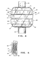
- Figure 4 is an exploded elevational view of the male and female housing portions of the construction shown in Figure 3.
- Figure 5 is a fragmentary view, similar in part to Figure 2, but showing a modification of the present invention where only a single thickness of the corrugated filter is "pinched" between vertical wall portions of the filter housing.
- the disposable filter assembly shown in Figures 1-5 is generally designated by the numeral 20.
- the filter assembly 20 includes a molded plastic housing, generally designated by the numeral 21 (Figs. 2 and 4), and including a male portion 22 and a female portion 23.
- the upper or male housing portion 22 includes an upper plenum wall 24.
- the upper plenum wall 24 includes a plenum 25, a rim 26, an upper port or inlet 30, and an upper rib 31.
- the disposable box filter assembly 20 is reversible, it can easily be understood by those skilled in the art that the upper port 30 can serve as an inlet or outlet, and thus that these terms may be used interchangeably.
- a plurality of reinforcing ribs 32 and a pair of opposed downwardly depending side walls 34 having a grooved portion 35, an ultrasonic energy ridge or portion 36, and a tapered or wedge-shaped portion or wall 37.
- the lower or female portion 23 of the plastic housing 21 includes a tongue portion 40, a first wall portion or first portion 41, a ramp portion 42, and a second portion or second wall portion 43, which is of greater thickness than the first portion 41. Also found on the lower or female portion 23 is a lower plenum wall 50 including a lower plenum 51, a lower rim 52, a lower port or inlet 53 and a lower ridge 54.
- the plastic housing 21 may be made of any practical transparent, opaque, or solid material. For most applications of the disposable box filter assembly 20, it is believed that a transparent plastic housing 21 will be preferred. Depending on the particular application, the housing may be made from many materials. A preferred material is K-Resin (KROI Grade). The housing may also be made from ABS, styrene, polycarbonate, nylon, polyester, or other thermoplastic materials.
- the plastic housing 21 having the male or upper housing portion 22 completely assembled and ultrasonically welded to the lower or female housing portion 23, and containing a corrugated filter 58.
- the plastic housing 21 assembled to this stage of manufacture shows the almost completed disposable filter assembly 20 before the end caps 60 are potted on.
- the corrugated filter 58 is has a predetermined number of pleats 59. The number of pleats required will depend on the particular application. Also, depending on the particular application, is the selection of the material for the corrugated filter 58. Widely used filter media are such as glass fiber and polypropylene, which can have a thickness in the range of 0.330 mm (.013") to 0.559 mm (022"). A typical thickness range is from 0.381 mm (.015") to 0.406 mm (.016").
- the sealing means of the present invention is best shown in Figures 2-3A.
- the prior art box filters required the sealing of the filter media to be done in a generally horizontal plane trapped between what may generally be called a top wall and a side wall of the filter.
- the paper was even bonded to the filter housing to get a proper seal. All of these types of housings or sealing arrangements cause various problems in the art.
- the box filter of the present invention is the first box filter to eliminate these problems by sealing the filter media in a generally vertical orientation. It can be seen in Figure 2 that one pleat 59 of the corrugated filter 58 is trapped between the tapered portion 37 of the downwardly depending side wall 34 forming a portion of the male housing 22, and the upstanding ridge 44 forming a portion of the lower or female housing portion 23.
- FIG. 3 An enlargement of a portion of the male and female housings are shown in Figure 3 and 3A to illustrate this.
- the tongue 40 of the female housing 23 will enter the grooved portion 35 of the male housing 22 permitting the ultrasonic ridge 36 to come in contact with the first portion 41 of the upstanding wall 39.
- the dimensions are so selected that when the ultrasonic ridge 36 touches first wall portion 41, the lower extremity of the wedge-shaped or tapered portion 37 of the downwardly depending side wall 34 is in close proximity or touching the ramp portion 42.
- the ultrasonic energy ridge 36 is progressively melted until the tongue 40 reaches proximate the bottom of the groove 35, and the housing portions have moved closer together.
- a typical dimension for the ultrasonic energy ridge is 0.457 mm (.018"), but other dimensions may be chosen, depending on the application. This amount of movement causes the wedge-shaped portion 37 of the downwardly depending wall 34 to attempt to move down the ramp portion 42 toward the U-shaped channel 75, separating second portion 43 and upstanding ridge 44.
- a preferred embodiment is to have the ramp 42 form an angle of 60° with the horizontal. Other angles may be used if desired.
- FIG 3A shows this movement without the corrugated filter installed for ease of understanding.
- the filter pleats 59 are compressed to about one-half their thickness, which is sufficient to compress the media to obtain a fluid-tight seal.
- FIG. 5 The versatility of the box filter of the present invention is shown by referring to Figure 5.
- a single thickness of filter paper or media indicated by the numeral 65, is compressed between the ridge 44 and the tapered wall 37.
- the tapered portion 37 may have vertical side walls or tapered side walls and still be within the scope of the present invention. However, it has been found that a 5° taper, which is the preferred draft for the molding process, produces very satisfactory results.
- Potting compound is applied to the end walls 68, as well as to the rectangular wall portions 70 of the end caps 60.
- the end cap 60 is then applied, the end cap is sealed not only to the opposed end wall 68 to close the chamber 66, but to the ends of the filter 58 in a fluid-tight manner, thereby forcing air to flow directly from upper port 30 through the corrugated filter 58 and exit lower port 53.
- the upper ridge 31 and the lower ridge 54 add strength to the corrugated filter 58, and prevents its distortion.
Landscapes
- Chemical & Material Sciences (AREA)
- Chemical Kinetics & Catalysis (AREA)
- Engineering & Computer Science (AREA)
- Mechanical Engineering (AREA)
- Infusion, Injection, And Reservoir Apparatuses (AREA)
- Filtering Of Dispersed Particles In Gases (AREA)
- Control Of Throttle Valves Provided In The Intake System Or In The Exhaust System (AREA)
- Air Bags (AREA)
- Control Of Motors That Do Not Use Commutators (AREA)
Claims (12)
- Wegwerffilteranordnung (20) mita) einem Gehäuse (21), das einen männliche (22) und einen weiblichen (23) Gehäuseabschnitt umfasst, die kanalförmig sind und zusammenpassen, wobei der männliche (22) und der weibliche (23) Gehäuseabschnitt eine kastenförmige Fluidkammer (66) ausbilden, die von einer oberen Luftraumwand (24), in der ein Einlass (30) vorgesehen ist, einer unteren Luftraumwand (50), in der ein Auslass (53) vorgesehen ist, einem Paar von gegenüberliegenden Seitenwänden (67), die die obere Luftraumwand (24) und die untere Luftraumwand (50) verbinden, und einem Paar von gegenüberliegenden, offenen Stirnwänden (68) gebildet wird, wobei der männnliche Gehäuseabschnitt (22) ein Paar nach unten herabhängender Seitenwände (34) aufweist und wenigstens ein Abschnitt der nach unten herabhängenden Seitenwände (34) des männlichen Gehäuseabschnitts (22) verformt und seitlich bewegt wurde, während die Filteranordnung (20) durch Ultraschall miteinander verschweißt wurde,b) einem gewellten Filterelement (58), das sich über die kastenförmige Fluidkammer (66) von einer der gegenüberliegenden Seitenwände (67) zu der anderen und über die Fluidströmungslinie zwischen dem Einlass (30) und dem Auslass (53) erstreckt, wobei ein Falz (59) oder eine einzelnde Dicke (65) an jedem Ende des wellenförmigen Filterelements (58) mechanisch in fluiddichter Abdichtung in einer insgesamt vertikalen Position durch die seitlichen Kräfte in der Nähe der gesamten Unterkanten des Filterelements (58) gehalten ist, die durch die nach unten herabhängenden Seitenwände (34) aufgebracht werden, undc) Endkappen (60), die die gegenüberliegenden Stirnwände (68) schließen und das Filterelement (58) zu den Endkappen (60) abdichten.
- Filteranordnung nach Anspruch 1, dadurch gekennzeichnet, dass die nach unten herabhängenden Seitenwände (34)einen Ultraschallenergie-Stegabschnitt (36) undeinen keilförmigen längsgestreckten Abschnitt (37) aufweisen, der sich verformt, wenn der männliche Gehäuseabschnitt (22) und der weibliche Gehäuseabschnitt (23) durch Ultraschall miteinander verschweißt werden.
- Filteranordnung nach Anspruch 2, dadurch gekennzeichnet, dassder männliche Gehäuseabschnitt (22)i) die obere Luftraumwand (24) undii) den Einlass (30) in der oberen Luftraumwand (24) aufweist, undder weibliche Gehäuseabschnitt (23) außerdemi) ein Paar von gegenüberliegenden, nach oben stehenden Seitenwänden (39), die jeweils von der unteren Luftraumwand (50) aus nach oben stehen, undaufweisen, unda) einen Zungenabschnitt (40),b) einen ersten Wandabschnitt (41),c) einen Rampenabschnitt (42) undd) einen zweiten Wandabschnitt (43)ii) ein Paar gegenüberliegender nach oben stehender Stege (44) aufweist, die innerhalb des weiblichen Gehäuseabschnitts (23) parallel und in einem vorher bestimmten Abstand von jeder Seitenwand des Paars gegenüberliegender Seitenwände (39) angeordnet sind.
- Filteranordnung nach Anspruch 3, dadurch gekennzeichnet, dass der Rampenabschnitt (42) von jeder Seitenwand des Paars gegenüberliegender nach oben stehender Seitenwände (39) sich ganz nahe zu jedem nach unten herabhängenden Seitenwandabschnitt (34) des männlichen Gehäuseabschnitts (22) befindet, wennn der Ultraschallenergie-Stegabschnitt (36) des männlichen Abschnitts in Kontakt mit dem ersten Wandabschnitt (41) des weiblichen Gehäuseabschnitts (23) steht.
- Filteranordnung nach Anspruch 4, dadurch gekennzeichnet, dass ein U-förmiger Kanal (75) zwischen jedem Steg des Paars der nach oben stehenden Stege (44) und jedem der zweiten Wandabschnitte (43) der nach oben stehenden Seitenwände (39) ausgebildet ist.
- Filteranordnung nach Anspruch 2, dadurch gekennzeichnet, dass nach dem Schmelzen des Ultraschall-Energiesteges (36) durch Schweißen der keilförmige längsgestreckte Abschnitt (37) jedes nach unten herabhängenden Seitenwandabschnitts (34) des männlichen Gehäuseabschnitts (22) jeden der Rampenabschnitte (42) der gegenüberliegenden nach oben stehenden Seitenwandabschnitte (39) des weiblichen Gehäuseabschnitts (23) kontaktiert und sich auf diesem eine Distanz nach unten bewegt hat, wodurch jeder der gegenüberliegenden nach unten herabhängenden Seitenwandabschnitte (34) näher zu den gegenüberliegenden, nach oben stehenden Stegen (44) plaziert wird.
- Wegwerffilteranordnung nach Anspruch 6, dadurch gekennzeichnet, dass sich das wellenförmige Filterelement (58) zwischen jedem der keilförmigen längsgestreckten Abschnitte (37) des männlichen Gehäuseabschnitts (22) erstreckt, wobei wenigstens ein Falz (59) an jedem Ende des wellenförmigen Filterelements (58) zwischen den keilförmigen längsgestreckten Abschnitten (37) des männlichen Gehäuseabschnitts (22) und den gegenüberliegenden nach oben stehenden Stegen (44) des weiblichen Gehäuseabschnitts (23) gefangen ist.
- Filteranordnung nach Anspruch 5, dadurch gekennzeichnet, dass sich das wellenförmige Filterelement (58) zwischen jedem der keilförmigen längsgestreckten Abschnitte (37) des männlichen Gehäuseabschnitts (22) erstreckt, wobei wenigstens ein Falz (59) an jedem Ende des wellenförmigen Filterelements (58) in dem U-förmigen Kanal (75) angeordnet ist.
- Filteranordnung nach Anspruch 7, dadurch gekennzeichnet, dass jeder der männlichen Gehäuseabschnitte (22) ein Paar von gegenüberliegenden oberen Stirnwandabschnitten aufweist, und jeder der weiblichen Gehäuseabschnitte (23) ein Paar von unteren gegenüberliegenden Stirnwandabschnitten aufweist, wobei die oberen und unteren Stirnwandabschnitte ein Paar von gegenüberliegenden Stirnwänden (68) bildet.
- Filteranordnung nach Anspruch 9, dadurch gekennzeichnet, dass die Endkappen (60) auf den gegenüberliegenden Stirnwänden (68) verkapselt sind.
- Verfahren zum Abdichten eines wellenförmigen Filterelements (58) innerhalb einer Filteranordnung, wobei das Verfahren die Schritte umfasst:a) Bereitstellen eines Gehäuses (21) mit einem männlichen oberen Gehäuseabschnitt (22) mit einem Einlass (30) und einem Paar insgesamt vertikaler Wandabschnitte (37) und einem weiblichen unteren Gehäuseabschnitt (23) mit einem Auslass (53) und einem Paar von insgesamt vertikalen Wandabschnitten (44), wobei die insgesamt vertikalen Wandabschnitte (37) des männlichen oberen Gehäuseabschnitts (22) so ausgelegt sind, dass sie sich seitlich in Richtung der insgesamt vertikalen Wandabschnitte (44) des weiblichen unteren Gehäuseabschnitts (23) bewegen, wenn ein Ultraschallschweißverfahren zur Verbindung des männlichen oberen Gehäuseabschnitts (22) mit dem weiblichen unteren Gehäuseabschnitt (23) verwendet wird,b) Einsetzen eines wellenförmigen Filters (58) in das Gehäuse (21), wobei ein Falz (59) oder eine einzelne Dicke (65) an jedem Ende des wellenförmigen Filters (58) in einer insgesamt vertikalen Ausrichtung zwischen den insgesamt vertikalen Wandabschnitten (37) des männlichen oberen Gehäuseabschnitts (22) und den insgesamt vertikalen Wandabschnitten (44) des weiblichen unteren Gehäuseabschnitts (23) eingesetzt wird,c) Verschweißen des männlichen oberen Gehäuseabschnitts (22) mit dem weiblichen unteren Gehäuseabschnitt (23) durch Ultraschall, wodurch die insgesamt vertikalen Wandabschnitte (37) des männlichen oberen Gehäuseabschnitts (22) seitlich in Richtung der insgesamt vertikalen Wandabschnitte (44) des weiblichen unteren Gehäuseabschnitts (23) bewegt werden, weshalb ein seitlicher Druck auf die Falze (59) oder die einzelnde Dicke (65) ausgeübt wird, um die Falze (59) oder die einzelnde Dicke (65) in dem Filtergehäuse (21) in der vertikalen Ausrichtung mechanisch abzudichten, undd) Verkapseln von Endkappen (60) auf das Filtergehäuse (21), um den wellenförmigen Filter (58) in Position zwischen dem Einlass (30) und dem Auslass (53) abzudichten.
- Verfahren nach Anspruch 11, bei dem die Bewegung des insgesamt vertikalen Wandabschnitts (37) des oberen Gehäuseabschnitts (22) in Richtung des insgesamt vertikalen Wandabschnitts (44) des unteren Gehäuseabschnitts (23) ausreicht, um die Medien auf ein Drittel bis auf die Hälfte ihrer ursprünglichen Dicke zusammenzudrücken.
Applications Claiming Priority (3)
| Application Number | Priority Date | Filing Date | Title |
|---|---|---|---|
| US08/083,076 US5376270A (en) | 1993-06-24 | 1993-06-24 | Box filter |
| PCT/US1994/007022 WO1995000225A1 (en) | 1993-06-24 | 1994-06-22 | Box filter |
| US83076 | 2002-02-26 |
Publications (3)
| Publication Number | Publication Date |
|---|---|
| EP0705131A1 EP0705131A1 (de) | 1996-04-10 |
| EP0705131A4 EP0705131A4 (de) | 1997-11-05 |
| EP0705131B1 true EP0705131B1 (de) | 2001-02-07 |
Family
ID=22176019
Family Applications (1)
| Application Number | Title | Priority Date | Filing Date |
|---|---|---|---|
| EP94920296A Expired - Lifetime EP0705131B1 (de) | 1993-06-24 | 1994-06-22 | Kastenfilter |
Country Status (7)
| Country | Link |
|---|---|
| US (3) | US5376270A (de) |
| EP (1) | EP0705131B1 (de) |
| AT (1) | ATE199064T1 (de) |
| AU (1) | AU7114794A (de) |
| CA (1) | CA2163978C (de) |
| DE (1) | DE69426672D1 (de) |
| WO (1) | WO1995000225A1 (de) |
Families Citing this family (48)
| Publication number | Priority date | Publication date | Assignee | Title |
|---|---|---|---|---|
| US5376270A (en) * | 1993-06-24 | 1994-12-27 | Porous Media Corporation | Box filter |
| US5512172A (en) * | 1994-06-10 | 1996-04-30 | Racal Filter Technologies, Ltd. | Method for sealing the edge of a filter medium to a filter assembly and the filter assembly produced thereby |
| DE4430333C2 (de) * | 1994-08-29 | 2000-02-17 | Mann & Hummel Filter | Filter |
| USD373637S (en) | 1995-05-08 | 1996-09-10 | Porous Media Corporation | Box filter |
| CA2177442A1 (en) * | 1995-05-29 | 1996-11-30 | Massimo Fini | Cardiotomy reservoir with internal filter |
| US5676778A (en) * | 1995-09-05 | 1997-10-14 | The Racal Corporation Canada Inc. | Method of manufacturing a filter assembly and the filter assembly produced thereby |
| GB9704241D0 (en) * | 1997-02-28 | 1997-04-16 | Smiths Industries Plc | Gas-treatment devices |
| DE19736290B4 (de) * | 1997-08-21 | 2007-03-29 | Carl Freudenberg Kg | Verfahren zur Herstellung einer Filteranordnung |
| ATE211941T1 (de) * | 1997-10-31 | 2002-02-15 | Clinix Gmbh | Filterelement mit filterelementaufnahme |
| US6207053B1 (en) * | 1998-03-12 | 2001-03-27 | Celgard Inc. | Thermoplastic, unibody transfer device |
| US6375700B1 (en) | 2000-06-23 | 2002-04-23 | Nelson Industries, Inc. | Direct flow filter |
| US6482247B2 (en) | 2000-06-23 | 2002-11-19 | Nelson Industries, Inc. | Multi-panel fluid filter with equalized contaminant passages |
| US6511599B2 (en) | 2000-12-18 | 2003-01-28 | Nelson Industries, Inc. | Multi-element cylindrical filter with equalized flow |
| US6464745B2 (en) | 2001-01-26 | 2002-10-15 | Freudenberg Nonwovens Limited Partnership | Minipleat synthetic air filter assembly |
| DE10131422C2 (de) * | 2001-06-29 | 2003-05-08 | Sandler Helmut Helsa Werke | Filterelement mit einem plissierten Filterpack |
| US6652613B2 (en) * | 2001-10-09 | 2003-11-25 | Carrier Corporation | Expandable media filter with flexible spacing ribbons |
| US6599343B2 (en) * | 2001-10-09 | 2003-07-29 | Carrier Corporation | Method and apparatus for assembling an expandable and disposable media filter |
| US6814773B2 (en) * | 2001-10-09 | 2004-11-09 | Carrier Corporation | Expandable media filter assembly |
| US6592643B2 (en) * | 2001-10-09 | 2003-07-15 | Carrier Corporation | Method and apparatus for assembling an expandable media filter |
| PL367425A1 (en) * | 2001-10-09 | 2005-02-21 | Carrier Corporation | Expandable and disposable media filter |
| US6740136B2 (en) * | 2001-10-12 | 2004-05-25 | 3M Innovative Properties Company | Interconnected filter frame and filter framing method |
| US7473360B2 (en) * | 2002-03-26 | 2009-01-06 | Pall Corporation | Length-adjustable filter cartridge end caps, filter cartridges employing, and methods of making, the same |
| NL1021570C2 (nl) * | 2002-10-01 | 2004-04-02 | Altena Services B V | Behuizing voor gasbehandelende componenten en paneel ten gebruike in een dergelijke behuizing. |
| EP1493478B1 (de) * | 2003-07-02 | 2007-04-04 | Filtertek Inc. | Halterung mit mehreren Brücken |
| DE10333185A1 (de) * | 2003-07-22 | 2005-02-24 | Robert Bosch Gmbh | Flacher Kraftstofffilter |
| US7048773B2 (en) * | 2003-08-04 | 2006-05-23 | Riedel Steve D | Universal vacuum filter cartridge |
| US7141101B2 (en) * | 2004-06-17 | 2006-11-28 | Home Health Medical Equipment Incorporated | Filter assembly with noise attenuation |
| US20060021932A1 (en) * | 2004-07-26 | 2006-02-02 | Darnell Justin R | Integrated flat panel filter and housing |
| EP2279782B1 (de) | 2004-12-23 | 2014-08-13 | EMD Millipore Corporation | Filterpatrone |
| DE102005004287B4 (de) * | 2005-01-28 | 2013-06-13 | Mann + Hummel Gmbh | Ölfiltereinheit |
| US7959699B2 (en) | 2007-09-20 | 2011-06-14 | Lennox Industries Inc. | Collapsible filter with folding arms |
| US8182571B2 (en) * | 2007-12-11 | 2012-05-22 | Lennox Industries Inc. | Frame for receiving a filter element and method for providing |
| US7833308B2 (en) * | 2008-01-30 | 2010-11-16 | Home Health Medical Equipment, Inc. | Filter assembly with multiple inlets and multiple filter members |
| EP2332630A1 (de) * | 2009-11-18 | 2011-06-15 | Covidien AG | Filter für einen Atemkreislauf |
| JP5609237B2 (ja) * | 2010-04-26 | 2014-10-22 | トヨタ紡織株式会社 | 自動変速機用流体フィルタ |
| CA2796430C (en) | 2010-04-30 | 2016-01-05 | Diversitech Corporation | Three-dimensional filter |
| JP5857574B2 (ja) * | 2011-09-17 | 2016-02-10 | 株式会社ジェイ・エム・エス | 血液フィルタ装置および血液フィルタ装置製造方法 |
| WO2013052091A1 (en) * | 2011-10-03 | 2013-04-11 | Entegris, Inc. | Modular filtration system |
| CN103084017A (zh) * | 2011-11-08 | 2013-05-08 | 昆山纬华电子科技有限公司 | 空气过滤器送风口结构 |
| EP2703057A3 (de) * | 2012-09-03 | 2016-04-13 | Carl Freudenberg KG | Fluidreiniger |
| EP2904300A1 (de) | 2012-10-01 | 2015-08-12 | Entegris, Inc. | Verbindungssystem und verfahren |
| JP6350241B2 (ja) * | 2014-11-25 | 2018-07-04 | トヨタ紡織株式会社 | エアクリーナ |
| US20170234575A1 (en) * | 2016-02-02 | 2017-08-17 | Seal Tite Llc | In-line duct filter |
| KR20190020060A (ko) * | 2016-08-29 | 2019-02-27 | 이엠디 밀리포어 코포레이션 | 압축된 주름 구성 필터에 대한 고정된 강성 벽 장치 |
| US10357731B2 (en) * | 2016-12-20 | 2019-07-23 | Baldwin Filters, Inc. | Filter with preformed end caps having notch feature |
| US20180339251A1 (en) * | 2017-05-23 | 2018-11-29 | Kx Technologies Llc | Method and apparatus for metal removal from drinking water |
| US11248993B2 (en) * | 2018-02-15 | 2022-02-15 | Colorado State University Research Foundation | Systems and methods for direct particle sampling |
| JP1716289S (ja) * | 2020-06-02 | 2022-05-31 | 換気機器用フィルター容器 |
Family Cites Families (16)
| Publication number | Priority date | Publication date | Assignee | Title |
|---|---|---|---|---|
| US3765536A (en) * | 1970-11-10 | 1973-10-16 | Pall Corp | Blood filter cascade |
| US3765537A (en) * | 1970-11-10 | 1973-10-16 | Pall Corp | Dual blood filter |
| US3712033A (en) * | 1971-06-01 | 1973-01-23 | Donaldson Co Inc | Air cleaner with hinged side walls |
| BE788210A (fr) * | 1971-09-16 | 1973-02-28 | Pall Corp | Boite filtrante |
| IT977658B (it) * | 1972-02-03 | 1974-09-20 | Knecht Filterwerke Gmbh | Cartuccia per filtro a forma di disco per motori a combustione |
| US4014797A (en) * | 1973-12-11 | 1977-03-29 | Burron Medical Products, Inc. | Intravenous injection apparatus and needle adapter with filter and method of making same |
| USD247252S (en) | 1976-02-12 | 1978-02-14 | Pall Corporation | Filter assembly |
| US4165287A (en) * | 1977-04-04 | 1979-08-21 | Cobe Laboratories, Inc. | Potting pleated membrane |
| US4163721A (en) * | 1977-04-04 | 1979-08-07 | Cobe Laboratories, Inc. | Edge sealed pleated membrane |
| US4133661A (en) * | 1977-11-25 | 1979-01-09 | General Motors Corporation | Air filter assembly |
| US4187182A (en) * | 1978-07-21 | 1980-02-05 | Pall Corporation | Box filter |
| USD260175S (en) | 1979-05-24 | 1981-08-11 | Carl Schleicher & Schull GmbH & Co., KG | Fluid filter unit |
| USD267117S (en) | 1980-07-22 | 1982-11-30 | Pall Corporation | Breathing circuit filter |
| US4617122A (en) * | 1984-08-01 | 1986-10-14 | Donaldson Company, Inc. | Crimp seal pleated filter assembly |
| DE8435227U1 (de) * | 1984-12-01 | 1985-02-28 | B. Braun Melsungen Ag, 3508 Melsungen | Filter fuer blutfuehrende leitungssysteme |
| US5376270A (en) * | 1993-06-24 | 1994-12-27 | Porous Media Corporation | Box filter |
-
1993
- 1993-06-24 US US08/083,076 patent/US5376270A/en not_active Expired - Lifetime
-
1994
- 1994-06-22 AU AU71147/94A patent/AU7114794A/en not_active Abandoned
- 1994-06-22 DE DE69426672T patent/DE69426672D1/de not_active Expired - Lifetime
- 1994-06-22 WO PCT/US1994/007022 patent/WO1995000225A1/en not_active Ceased
- 1994-06-22 AT AT94920296T patent/ATE199064T1/de not_active IP Right Cessation
- 1994-06-22 CA CA002163978A patent/CA2163978C/en not_active Expired - Fee Related
- 1994-06-22 EP EP94920296A patent/EP0705131B1/de not_active Expired - Lifetime
-
1995
- 1995-06-07 US US08/479,863 patent/US5489352A/en not_active Expired - Lifetime
- 1995-10-12 US US08/542,280 patent/US5599448A/en not_active Expired - Lifetime
Also Published As
| Publication number | Publication date |
|---|---|
| EP0705131A4 (de) | 1997-11-05 |
| US5599448A (en) | 1997-02-04 |
| US5489352A (en) | 1996-02-06 |
| AU7114794A (en) | 1995-01-17 |
| WO1995000225A1 (en) | 1995-01-05 |
| DE69426672D1 (de) | 2001-03-15 |
| CA2163978A1 (en) | 1995-01-05 |
| ATE199064T1 (de) | 2001-02-15 |
| US5376270A (en) | 1994-12-27 |
| CA2163978C (en) | 2005-03-15 |
| EP0705131A1 (de) | 1996-04-10 |
Similar Documents
| Publication | Publication Date | Title |
|---|---|---|
| EP0705131B1 (de) | Kastenfilter | |
| DE3224128C3 (de) | Druckstroemfilter, verfahren und werkzeug zu seiner herstellung | |
| JP4372356B2 (ja) | ハウジング、フィルター、およびフィルターインサート | |
| AU678537B2 (en) | Medical container port | |
| US5049274A (en) | Friction welding process and filter formed thereby | |
| US5512172A (en) | Method for sealing the edge of a filter medium to a filter assembly and the filter assembly produced thereby | |
| WO1995034367B1 (en) | Improved method for sealing the edge of a filter medium to a filter assembly and the filter assembly produced thereby | |
| US5885499A (en) | Method for the manufacture of filter wells | |
| JP6118264B2 (ja) | 濾過デバイス及び方法 | |
| US3979295A (en) | Folded membrane dialyzer with mechanically sealed edges | |
| US3864265A (en) | Edge sealed folded membrane | |
| KR20020021653A (ko) | 연속 스트립 프레임을 갖는 필터 | |
| US4990251A (en) | Resilient sealing ring | |
| GB2252922A (en) | Pleated filter elements | |
| US6193830B1 (en) | Pleated filter insert and method of manufacture | |
| JP2004536709A (ja) | カセットフィルター | |
| WO1997009107A1 (en) | Method of manufacturing a filter assembly and the filter assembly produced thereby | |
| US20010013670A1 (en) | Process for producing a filter cartridge, and a tool for implementing the process | |
| JP2001520130A (ja) | 合成材料をフィルタ材料のまわりにインサート成形するための射出成形型、流体の濾過用フィルタおよびそのようなフィルタの製造方法 | |
| CA1221644A (en) | End closure for tubular housing | |
| JPH01203010A (ja) | フィルタユニットの成形方法 | |
| CN218871615U (zh) | 一种塑料v型空气过滤器 | |
| US20020174772A1 (en) | Filter cassette and injection-molding tool for manufacturing the filter cassette frame | |
| CN120513127A (zh) | 具有可变几何形状密封构件的过滤系统和过滤元件 | |
| WO2010014713A1 (en) | Filter with molded-in-place filter material |
Legal Events
| Date | Code | Title | Description |
|---|---|---|---|
| PUAI | Public reference made under article 153(3) epc to a published international application that has entered the european phase |
Free format text: ORIGINAL CODE: 0009012 |
|
| 17P | Request for examination filed |
Effective date: 19951208 |
|
| AK | Designated contracting states |
Kind code of ref document: A1 Designated state(s): AT BE CH DE DK ES FR GB GR IE IT LI LU MC NL PT SE |
|
| A4 | Supplementary search report drawn up and despatched |
Effective date: 19970918 |
|
| AK | Designated contracting states |
Kind code of ref document: A4 Designated state(s): AT BE CH DE DK ES FR GB GR IE IT LI LU MC NL PT SE |
|
| 17Q | First examination report despatched |
Effective date: 19980824 |
|
| GRAG | Despatch of communication of intention to grant |
Free format text: ORIGINAL CODE: EPIDOS AGRA |
|
| GRAG | Despatch of communication of intention to grant |
Free format text: ORIGINAL CODE: EPIDOS AGRA |
|
| GRAH | Despatch of communication of intention to grant a patent |
Free format text: ORIGINAL CODE: EPIDOS IGRA |
|
| GRAH | Despatch of communication of intention to grant a patent |
Free format text: ORIGINAL CODE: EPIDOS IGRA |
|
| GRAA | (expected) grant |
Free format text: ORIGINAL CODE: 0009210 |
|
| AK | Designated contracting states |
Kind code of ref document: B1 Designated state(s): AT BE CH DE DK ES FR GB GR IE IT LI LU MC NL PT SE |
|
| PG25 | Lapsed in a contracting state [announced via postgrant information from national office to epo] |
Ref country code: SE Free format text: THE PATENT HAS BEEN ANNULLED BY A DECISION OF A NATIONAL AUTHORITY Effective date: 20010207 Ref country code: NL Free format text: LAPSE BECAUSE OF FAILURE TO SUBMIT A TRANSLATION OF THE DESCRIPTION OR TO PAY THE FEE WITHIN THE PRESCRIBED TIME-LIMIT Effective date: 20010207 Ref country code: LI Free format text: LAPSE BECAUSE OF FAILURE TO SUBMIT A TRANSLATION OF THE DESCRIPTION OR TO PAY THE FEE WITHIN THE PRESCRIBED TIME-LIMIT Effective date: 20010207 Ref country code: IT Free format text: LAPSE BECAUSE OF FAILURE TO SUBMIT A TRANSLATION OF THE DESCRIPTION OR TO PAY THE FEE WITHIN THE PRE;WARNING: LAPSES OF ITALIAN PATENTS WITH EFFECTIVE DATE BEFORE 2007 MAY HAVE OCCURRED AT ANY TIME BEFORE 2007. THE CORRECT EFFECTIVE DATE MAY BE DIFFERENT FROM THE ONE RECORDED.SCRIBED TIME-LIMIT Effective date: 20010207 Ref country code: GR Free format text: LAPSE BECAUSE OF NON-PAYMENT OF DUE FEES Effective date: 20010207 Ref country code: FR Free format text: LAPSE BECAUSE OF FAILURE TO SUBMIT A TRANSLATION OF THE DESCRIPTION OR TO PAY THE FEE WITHIN THE PRESCRIBED TIME-LIMIT Effective date: 20010207 Ref country code: ES Free format text: THE PATENT HAS BEEN ANNULLED BY A DECISION OF A NATIONAL AUTHORITY Effective date: 20010207 Ref country code: CH Free format text: LAPSE BECAUSE OF FAILURE TO SUBMIT A TRANSLATION OF THE DESCRIPTION OR TO PAY THE FEE WITHIN THE PRESCRIBED TIME-LIMIT Effective date: 20010207 Ref country code: BE Free format text: LAPSE BECAUSE OF FAILURE TO SUBMIT A TRANSLATION OF THE DESCRIPTION OR TO PAY THE FEE WITHIN THE PRESCRIBED TIME-LIMIT Effective date: 20010207 Ref country code: AT Free format text: LAPSE BECAUSE OF FAILURE TO SUBMIT A TRANSLATION OF THE DESCRIPTION OR TO PAY THE FEE WITHIN THE PRESCRIBED TIME-LIMIT Effective date: 20010207 |
|
| REF | Corresponds to: |
Ref document number: 199064 Country of ref document: AT Date of ref document: 20010215 Kind code of ref document: T |
|
| REG | Reference to a national code |
Ref country code: CH Ref legal event code: EP |
|
| REF | Corresponds to: |
Ref document number: 69426672 Country of ref document: DE Date of ref document: 20010315 |
|
| REG | Reference to a national code |
Ref country code: IE Ref legal event code: FG4D |
|
| PG25 | Lapsed in a contracting state [announced via postgrant information from national office to epo] |
Ref country code: PT Free format text: LAPSE BECAUSE OF FAILURE TO SUBMIT A TRANSLATION OF THE DESCRIPTION OR TO PAY THE FEE WITHIN THE PRESCRIBED TIME-LIMIT Effective date: 20010507 Ref country code: DK Free format text: LAPSE BECAUSE OF FAILURE TO SUBMIT A TRANSLATION OF THE DESCRIPTION OR TO PAY THE FEE WITHIN THE PRESCRIBED TIME-LIMIT Effective date: 20010507 |
|
| PG25 | Lapsed in a contracting state [announced via postgrant information from national office to epo] |
Ref country code: DE Free format text: LAPSE BECAUSE OF FAILURE TO SUBMIT A TRANSLATION OF THE DESCRIPTION OR TO PAY THE FEE WITHIN THE PRESCRIBED TIME-LIMIT Effective date: 20010508 |
|
| PG25 | Lapsed in a contracting state [announced via postgrant information from national office to epo] |
Ref country code: LU Free format text: LAPSE BECAUSE OF NON-PAYMENT OF DUE FEES Effective date: 20010622 Ref country code: IE Free format text: LAPSE BECAUSE OF NON-PAYMENT OF DUE FEES Effective date: 20010622 Ref country code: GB Free format text: LAPSE BECAUSE OF NON-PAYMENT OF DUE FEES Effective date: 20010622 |
|
| PG25 | Lapsed in a contracting state [announced via postgrant information from national office to epo] |
Ref country code: MC Free format text: LAPSE BECAUSE OF NON-PAYMENT OF DUE FEES Effective date: 20010630 |
|
| NLV1 | Nl: lapsed or annulled due to failure to fulfill the requirements of art. 29p and 29m of the patents act | ||
| EN | Fr: translation not filed | ||
| REG | Reference to a national code |
Ref country code: CH Ref legal event code: PL |
|
| PLBE | No opposition filed within time limit |
Free format text: ORIGINAL CODE: 0009261 |
|
| STAA | Information on the status of an ep patent application or granted ep patent |
Free format text: STATUS: NO OPPOSITION FILED WITHIN TIME LIMIT |
|
| 26N | No opposition filed | ||
| GBPC | Gb: european patent ceased through non-payment of renewal fee |
Effective date: 20010622 |